

IRPLLNR7 - International Rectifier
IRPLLNR7 - International Rectifier
IRPLLNR7 - International Rectifier

You also want an ePaper? Increase the reach of your titles
YUMPU automatically turns print PDFs into web optimized ePapers that Google loves.
15. Preheat Mode<br />
When the ballast reaches the end of the UVLO mode, the Preheat mode is entered. At this point the<br />
ballast control oscillator of the IRS2166D has begun to operate and the half-bridge output is driving<br />
the resonant load (lamp) circuit. There is an initial startup frequency that is much higher than the<br />
steady state Preheat mode frequency that lasts for only a short duration. This is done to ensure that the<br />
initial voltage appearing across the lamp at the startup of oscillation does not exceed the minimum<br />
lamp ignition voltage. If, at the initiation of oscillation of the half-bridge, the voltage across the lamp is<br />
large enough, a visible flash of the lamp occurs which should be avoided. This in effect is a cold strike<br />
of the lamp, which could shorten the life of the lamp.<br />
The ballast control section oscillator of the IRS2166D is similar to oscillators found in many popular<br />
PWM voltage regulator ICs and consists of a timing capacitor and resistor connected to ground.<br />
Resistors RT and RPH program a current that determines the ramp up time of capacitor CT. The<br />
downward ramping time of CT is the deadtime between the switching off of the LO (HO) and the<br />
switching on of the HO (LO) pins on the IRS2166D. The Preheat mode frequency of oscillation is<br />
determined from the parallel resistance of RT and RPH. It is selected such that the voltage appearing<br />
across the lamp is below the minimum lamp ignition voltage while supplying enough current to<br />
preheat the lamp filaments to the correct emission temperature within the Preheat mode period. The<br />
preheating of the lamp filaments is performed with a constant voltage during the Preheat mode. The<br />
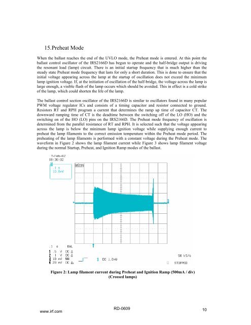
waveform in Figure 2 shows the lamp filament current while Figure 3 shows lamp filament voltage<br />
during the normal Startup, Preheat, and Ignition Ramp modes of the ballast.<br />
Figure 2: Lamp filament current during Preheat and Ignition Ramp (500mA / div)<br />
(Crossed lamps)<br />
www.irf.com<br />
RD-0609<br />
10


