Specification - Power Transmission Corporation of Uttarakhand ...
Specification - Power Transmission Corporation of Uttarakhand ...
Specification - Power Transmission Corporation of Uttarakhand ...

You also want an ePaper? Increase the reach of your titles
YUMPU automatically turns print PDFs into web optimized ePapers that Google loves.
<strong>Power</strong> <strong>Transmission</strong> <strong>Corporation</strong> <strong>of</strong> <strong>Uttarakhand</strong> Ltd.<br />
Technical <strong>Specification</strong><br />
Index<br />
Section-1: Page-2 to 35<br />
Section-2: Page-36 to 40<br />
Section-3: Page-41 to 44<br />
Section-4: Page-45 to 46<br />
Section-5: Page-47 to 70<br />
Technical Particular and Schedules: Page-71 to 95<br />
Schedule for Submission <strong>of</strong> Drawings: 96<br />
220 KV S/C RISHIKESH-DHARASU & CHAMBA-DHARASU <strong>Transmission</strong> Line<br />
1<br />
http://www.ptcul.org/ten_02_08_08_spcification.pdf
<strong>Power</strong> <strong>Transmission</strong> <strong>Corporation</strong> <strong>of</strong> <strong>Uttarakhand</strong> Ltd.<br />
SECTION – 1<br />
1. General requirement <strong>of</strong> specification (Technical)<br />
1.1 General<br />
This part covers technical conditions pursuant to the contract and will form an<br />
integral part <strong>of</strong> the contract. The following provisions shall supplement all the<br />
detailed technical specifications and requirement brought out in the accompanying<br />
technical specifications (Part-III). The contractor’s proposal shall be based on the use<br />
<strong>of</strong> equipment and material complying fully with the requirement specified herein. It is<br />
recognized that the contractor may have standardized on the use <strong>of</strong> certain<br />
components, materials, processes, or procedures different than those specified herein.<br />
Alternate proposals <strong>of</strong>fering similar equipment based on the manufacturer’s standard<br />
practice will also be considered, provided such proposals met the specified design,<br />
standards and performance requirement and are acceptable to the purchaser.<br />
1.2 Technical Qualifying Requirement<br />
The Contractor must have executed similar works in hilly terrain i.e. he must have<br />
constructed either a 132 KV double circuit line <strong>of</strong> minimum length 20 km or a 132<br />
KV single circuit line <strong>of</strong> minimum length 40 km in the last three years and these<br />
works should be working satisfactorily.<br />
1.3 LIMIT OF CONTRACT<br />
Equipment furnished shall be complete in every respect with all mounting, fitting<br />
fixtures and standard accessories normally provided with such equipment and/or<br />
needed for erection, completion and safe operation <strong>of</strong> the equipment as required by<br />
applicable codes though they may not have been specifically detailed in the technical<br />
specifications, unless included in the list <strong>of</strong> exclusion. A similar standard component /<br />
part <strong>of</strong> similar standard equipment provided, shall be inter changeable with one<br />
another.<br />
1.4 ENGINEERING DATA<br />
All the +s (except drawings <strong>of</strong> towers and tower foundations) <strong>of</strong> equipment being<br />
supplied by the contractor shall be submitted by the Contractor to Dy. General<br />
Manger (Engg.) for his approval. The Dy. General Manager (Engg.) shall approve the<br />
drawing and action for its inspection or waiver after receipt <strong>of</strong> the information <strong>of</strong><br />
readiness <strong>of</strong> the material at works <strong>of</strong> the contractor and issue Dispatch Instruction.<br />
The design and drawings <strong>of</strong> towers and tower foundations shall be supplied by<br />
PTCUL, however the tower designs will have to be type tested by the Contractor.<br />
The furnishing <strong>of</strong> engineering data by the contractor shall be in accordance with the<br />
schedule as specified in the technical specification. The review <strong>of</strong> these data by the<br />
Engineering will cover only general conformance <strong>of</strong> the data to the specifications and<br />
220 KV S/C RISHIKESH-DHARASU & CHAMBA-DHARASU <strong>Transmission</strong> Line<br />
2<br />
http://www.ptcul.org/ten_02_08_08_spcification.pdf
<strong>Power</strong> <strong>Transmission</strong> <strong>Corporation</strong> <strong>of</strong> <strong>Uttarakhand</strong> Ltd.<br />
documents, and <strong>of</strong> the dimensions which might affect plant layout. This review by<br />
PTCUL may not indicate a thorough review <strong>of</strong> all dimensions, quantities and details<br />
<strong>of</strong> equipment, material, any devices or items indicated or the accuracy <strong>of</strong> the<br />
information submitted. This review and/or approval by PTCUL shall not be<br />
constructed by the contractor as limiting any <strong>of</strong> his responsibilities and liabilities for<br />
mistakes and deviations from the requirement specified under these specifications and<br />
documents.<br />
All Engineering data submitted by the contractor after final process including review<br />
and approval by PTCUL shall form part <strong>of</strong> the contract documents and the entire<br />
works covered under these specifications shall be performed in strictly conformity,<br />
unless otherwise expressly requested by PTCUL in writing.<br />
1.5 DRAWINGS<br />
1.0.0 All drawings submitted by the Contractor including those submitted at the time <strong>of</strong><br />
tender shall be in sufficient details to indicate the type, size weight <strong>of</strong> each<br />
component, or any other information specifically requested in the specifications.<br />
1.0.1 Each drawing submitted by the Contractor shall be clearly marked with the name <strong>of</strong><br />
the Purchaser, the unit designation, the specification’s title, the specification number<br />
and the name <strong>of</strong> the Project. All titles, noting, markings and writings on the drawing<br />
shall be in English.<br />
1.0.2 The drawings submitted by the contractor shall be reviewed by PTCUL as far as<br />
practicable with the time schedule as mutually agreed and shall be modified by the<br />
contractor if any modifications and/or corrections are required by PTCUL. The<br />
Contractor shall incorporate such modifications and/or correction and submit the final<br />
drawings for approval.<br />
1.0.3 The drawing will be sent for approval to PTCUL in five copies. One print <strong>of</strong> such<br />
drawing will be returned to the contractor, by the Dy. General Manager<br />
(Engineering.) marked “Approved”. After approval <strong>of</strong> such drawing the contractor<br />
shall there upon furnish the owner with four prints.<br />
1.0.4 Further work by the contractor shall be in strict accordance with these drawings and<br />
no deviation shall be permitted without the written approval <strong>of</strong> PTCUL, if so<br />
required.<br />
1.0.5 All manufacturing and fabrication work in connection with the equipment prior to the<br />
approval <strong>of</strong> the drawing shall be at the contractor’s risk. The Contractor may make<br />
any change, in the design which are necessary to make the equipment conform to the<br />
provisions and intent <strong>of</strong> Contract and such work with changes will again be subject to<br />
prior approval by PTCUL. Approval <strong>of</strong> contractor’s drawings by PTCUL shall not<br />
relieve the contractor <strong>of</strong> any <strong>of</strong> his responsibilities and liabilities under this Contract.<br />
220 KV S/C RISHIKESH-DHARASU & CHAMBA-DHARASU <strong>Transmission</strong> Line<br />
3<br />
http://www.ptcul.org/ten_02_08_08_spcification.pdf
<strong>Power</strong> <strong>Transmission</strong> <strong>Corporation</strong> <strong>of</strong> <strong>Uttarakhand</strong> Ltd.<br />
1.6 MANUFACTURING SCHEDULE<br />
1.0.0 The contractor shall submit to PTCUL his manufacture and delivery schedules for all<br />
material within thirty (30) days, from the date <strong>of</strong> letter <strong>of</strong> Award. Such schedules<br />
shall be in the line with the detailed net work for all phases <strong>of</strong> the work <strong>of</strong> the<br />
contractor. Schedules shall also include the materials and equipment purchase from<br />
outside supplier.<br />
1.0.1 The contractor may submit the list <strong>of</strong> vendors and drawings <strong>of</strong> material to be supplied<br />
by him along with his <strong>of</strong>fer. The corporation however may or may not accept any<br />
vendor and may propose the name <strong>of</strong> any other vendor.<br />
1.7 REFERENCE OF STANDARDS<br />
1.0.0 The codes, and/or standards referred to in these specifications shall govern, in all<br />
cases wherever such references are made. In case <strong>of</strong> any conflict between such codes<br />
and/or standards referred to shall mean the latest revisions, amendments Changes<br />
adopted and published by relevant agencies. In case <strong>of</strong> any further conflict in this<br />
matter, the same shall be referred to PTCUL, whose decision shall be final and<br />
binding.<br />
1.0.1 It shall be the responsibility <strong>of</strong> the Contractor to ensure that the quality and<br />
specifications <strong>of</strong> the materials and works be as per the latest norms specified<br />
by the Bureau <strong>of</strong> Indian Standards, IEC, IEEE, etc. In case the parameters<br />
given in this specification are less stringent than the national or international<br />
norms or standards, it shall be the duty <strong>of</strong> the Contractor to point out the<br />
differences in due time and to gain explicit clarification and separate approval<br />
from PTCUL for the same .In case any standard is revised , it shall be the duty<br />
<strong>of</strong> the Contractor to point out the differences or revisions to PTCUL in due<br />
time so that the latest and more stringent specifications may be adhered to<br />
1.0.2 The Codes and/or Standards referred to in <strong>Specification</strong>s shall govern, in all<br />
cases wherever such references are made. In case <strong>of</strong> a conflict between such<br />
Codes and/or Standards and the specifications, the Contractor must<br />
immediately point out the same to PTCUL and seek clarification about the<br />
same and in case PTCUL insists that notwithstanding the standards, the<br />
previously specified parameters be adhered to, get explicit approval from<br />
PTCUL for the same.. Such Codes and/or Standards, referred to shall mean the<br />
latest revisions, amendments/changes adopted and published by the relevant<br />
agencies.<br />
1.0.3 Other internationally acceptable standards which ensure equal or high<br />
performance then those specified shall also be adopted, subject to approval by<br />
PTCUL.<br />
220 KV S/C RISHIKESH-DHARASU & CHAMBA-DHARASU <strong>Transmission</strong> Line<br />
4<br />
http://www.ptcul.org/ten_02_08_08_spcification.pdf
<strong>Power</strong> <strong>Transmission</strong> <strong>Corporation</strong> <strong>of</strong> <strong>Uttarakhand</strong> Ltd.<br />
1.8 DESIGN IMPROVEMENT<br />
1.8.1 PTCUL or the contractor may propose changes in the specification <strong>of</strong> the<br />
equipments or quality there<strong>of</strong> and if the parties agree upon any such<br />
changes, the specifications shall be modified accordingly.<br />
1.8.2 If any agreed upon change is such that it affects the price and schedule <strong>of</strong><br />
completion, the parties shall agree in writing as to the extent <strong>of</strong> any change<br />
in the price and/or schedule <strong>of</strong> completion before the contractor proceeds<br />
with the change. Following such agreement, the provision there<strong>of</strong> shall be<br />
deemed to have been amended accordingly.<br />
1.9 QUALITY ASSURANCE<br />
1.0.0 QUALITY ASSURANCE PROGRAMME<br />
To ensure that the equipment and services under the Scope <strong>of</strong> this contract<br />
whether manufactured or performed within the Contractor’s work or at his Sub<br />
contractor’s premises or at the purchaser’s site or at any other place <strong>of</strong> work are in<br />
accordance with the specifications. The Contractor shall adopt suitable Quality<br />
Assurance Programme (QAP) to control such activities at all point, necessary.<br />
The quality Assurance Programme <strong>of</strong> the Contractor shall generally cover the<br />
following:-<br />
b) His Organizational structure for the management and implementation <strong>of</strong> the<br />
proposed Quality Assurance Programme.<br />
c) Documentation control system<br />
d) Qualification data for bidder key personnel.<br />
e) The procedure for purchase <strong>of</strong> materials, parts, components, and selection <strong>of</strong> sub<br />
contractor’s services including vendor analysis, source inspection. Incoming rawmaterial<br />
inspection, verification <strong>of</strong> materials purchase. Etc.<br />
f) System for shop manufacturing and site erection controls including process<br />
controls and fabrication and assembly controls.<br />
g) Control <strong>of</strong> non-conforming items and system for corrective actions.<br />
h) Control <strong>of</strong> calibration and testing <strong>of</strong> measuring and testing equipment.<br />
i) Inspection and testing procedure both for manufacture and field activities.<br />
j) System for indication and appraisal <strong>of</strong> inspection status.<br />
k) System for quality audits.<br />
l) System for authorizing release <strong>of</strong> manufactured product to the purchaser.<br />
m) System for maintenance <strong>of</strong> records.<br />
n) System for handling storage and delivery and<br />
o) A quality plan detailing out the specific quality control procedure adopted for<br />
controlling the quality characteristics relevant to such item <strong>of</strong> equipment.<br />
220 KV S/C RISHIKESH-DHARASU & CHAMBA-DHARASU <strong>Transmission</strong> Line<br />
5<br />
http://www.ptcul.org/ten_02_08_08_spcification.pdf
<strong>Power</strong> <strong>Transmission</strong> <strong>Corporation</strong> <strong>of</strong> <strong>Uttarakhand</strong> Ltd.<br />
1.0.1 QUALITY ASSURANCE DOCUMENTS<br />
The contractor shall be required to submit the following quality Assurance<br />
Documents within the three weeks <strong>of</strong> award <strong>of</strong> the Contract.<br />
i) Material Test Report on components as specified the by specification.<br />
ii) The inspection plan with verification, inspection plan check, point’s<br />
verification sketches, if used and methods used to verify that the<br />
inspection and testing points in the inspection plan were performed<br />
satisfactorily.<br />
iii) Factory test results for testing required as per applicable codes and<br />
standards referred in the specification Quality Assurance Documents 3<br />
points<br />
1.1 INSPECTION, TESTING AND INSPECTION CERTIFICATE<br />
1.1.0 PTCUL’s duly authorized representative and/or an outside inspection agency acting<br />
on behalf <strong>of</strong> the purchaser (PTCUL) shall at all reasonable times have access to the<br />
Contractor’s premises or works and shall have the power, at all reasonable times to<br />
inspect and examine the materials and workmanship <strong>of</strong> the works during its<br />
manufacturer or erection and if part <strong>of</strong> the work is being manufactured or assembled<br />
on other premises or work, the Contractor shall obtain for PTCUL and for its duly<br />
authorized representative permission to inspect as if the works were manufactured or<br />
assembled on the contractor’s own premises or works.<br />
1.1.1 The Contractor shall give PTCUL or its authorized representative fifteen days written<br />
notice <strong>of</strong> any material being ready for testing. Such test shall be on the contractor’s<br />
account except for the expenses <strong>of</strong> the inspector. PTCUL’s Inspector, unless<br />
witnessing <strong>of</strong> the test is explicitly waived, will attend such test within Seven days <strong>of</strong><br />
the date on which the equipment is notified as being ready for test/inspection.<br />
1.1.2 PTCUL shall within Seven (7) days from the date <strong>of</strong> inspection as defined herein<br />
give notice in writing to the contractor <strong>of</strong> any objection to any drawings and all or any<br />
equipment and workmanship which in his opinion is not in accordance with the<br />
contract. The Contractor shall give due consideration to such objection and shall<br />
either make the modifications that may be necessary to meet the said objections or<br />
shall conform in writing to PTCUL giving reasons therein, that no modifications are<br />
necessary to comply with the contract.<br />
1.1.3 When the factory tests have been completed at the contractor’s or sub-contractor’s<br />
work, PTCUL shall issue a certificate to this effect within Seven (7) days after<br />
completion <strong>of</strong> tests but if the tests are not witnessed by PTCUL. Inspection, the<br />
certificate shall be issued within Seven (7) days <strong>of</strong> the receipt <strong>of</strong> Contractor’s test<br />
220 KV S/C RISHIKESH-DHARASU & CHAMBA-DHARASU <strong>Transmission</strong> Line<br />
6<br />
http://www.ptcul.org/ten_02_08_08_spcification.pdf
<strong>Power</strong> <strong>Transmission</strong> <strong>Corporation</strong> <strong>of</strong> <strong>Uttarakhand</strong> Ltd.<br />
certificate by PTCUL/Inspection. The completion <strong>of</strong> these tests or the issue <strong>of</strong> the<br />
certificate shall not bind the owner to accept the equipment, should it, on further tests<br />
after erection be found not to comply with the contract.<br />
1.1.4 In all cases where the contract provides for tests whether at the premises or works <strong>of</strong><br />
the contractor or any sub contractor, the contractor, except where otherwise specified,<br />
shall provide free <strong>of</strong> charge such items as labour, materials, electricity, fuel, water<br />
stores, apparatus and instruments as may be reasonably demanded by PTCUL’s<br />
Inspector or PTCUL’s authorized representative to carry out effectively such tests <strong>of</strong><br />
the equipment in accordance with the Contract and shall give facilities to PTCUL or<br />
to its authorized representative in accomplishing testing.<br />
1.1.5 The Inspection by PTCUL and issue <strong>of</strong> inspection certificate thereon shall in no way<br />
limit the liabilities and responsibilities <strong>of</strong> the contract in respect <strong>of</strong> the agreed quality<br />
assurance Programme forming a part <strong>of</strong> the contract.<br />
1.1.6 After successful inspection and test, the purchaser shall issue a material dispatch<br />
clearance certificate authorizing the contractor to dispatch the inspected/tested<br />
material. No material shall be dispatched without issue <strong>of</strong> dispatch clearance<br />
certificate from the purchaser. In case inspection/test have been waived <strong>of</strong>f by the<br />
purchaser even then contractor shall not dispatch the material without issue <strong>of</strong><br />
dispatch clearance certificate.<br />
1.1.7 The Contractor shall keep PTCUL informed in advance about the time <strong>of</strong> starting<br />
and <strong>of</strong> the progress <strong>of</strong> manufacture and fabrication <strong>of</strong> various parts at various stages,<br />
so that arrangements could be made for inspection<br />
1.1.8 The acceptance <strong>of</strong> any part <strong>of</strong> items shall in no way relieve the Contractor <strong>of</strong> any part<br />
<strong>of</strong> his responsibility for meeting all the requirements <strong>of</strong> the specifications<br />
1.1.9 PTCUL or its representative shall have free access at all reasonable times to those<br />
parts <strong>of</strong> the Contractor’s works which are concerned with the fabrication <strong>of</strong> PTCUL’s<br />
materials for satisfying himself that the fabrication is being done in accordance with<br />
the provisions <strong>of</strong> the <strong>Specification</strong>s<br />
1.1.10 Unless specified otherwise, inspection shall be made at he place <strong>of</strong> manufacture prior<br />
to dispatch and shall be concluded so as not to interfere unnecessarily with the<br />
operation <strong>of</strong> the work<br />
1.1.11 Should any member <strong>of</strong> the structure be found not to comply with the supplied<br />
documents, it shall be liable to rejection. No member once rejected shall be<br />
resubmitted for inspection, except in cases where PTCUL or its authorized<br />
representative considers that the defects can be recited<br />
220 KV S/C RISHIKESH-DHARASU & CHAMBA-DHARASU <strong>Transmission</strong> Line<br />
7<br />
http://www.ptcul.org/ten_02_08_08_spcification.pdf
<strong>Power</strong> <strong>Transmission</strong> <strong>Corporation</strong> <strong>of</strong> <strong>Uttarakhand</strong> Ltd.<br />
1.1.12 Defects which may appear during fabrication shall be made good with the consent <strong>of</strong>,<br />
and according to the procedure proposed by the Contractor and by PTCUL.<br />
1.1.13 All gauges and templates necessary to satisfy PTCUL shall be supplied by the<br />
Contractor<br />
1.1.14 The Contractor shall make provisions and arrangements for all documents,<br />
tools and plants, instruments, reference standards , literature ,drawings ,<br />
engineers , technicians and manpower required for the conduction <strong>of</strong> the<br />
inspection<br />
1.2 PACKING<br />
All the equipments shall be suitably protected, coated, covered on boxed and crated to<br />
prevent damage or deterioration during transit, handling and storage at site till the<br />
time or erection. While packing all the materials, the limitations from the point <strong>of</strong><br />
view <strong>of</strong> availability <strong>of</strong> Railway Wagon size in India should be taken into account. The<br />
Contractor shall be responsible for any loss or damage during transportation, handling<br />
and storage due to improper packing. The details furnished are for the guidance <strong>of</strong><br />
Bidders. PTCUL takes no responsibility <strong>of</strong> the availability <strong>of</strong> wagon and variations in<br />
dimensions.<br />
1.3 DESIGN CO-ORDINATION<br />
The contractor may be responsible for the selection and design <strong>of</strong> appropriate<br />
equipments to provide the best co-ordinate performance <strong>of</strong> the entire system. The<br />
basic design requirements are detailed out in Technical <strong>Specification</strong>s. The design <strong>of</strong><br />
various components, sub-assemblies and assemblies shall be so done, so that it<br />
facilitates easy field assembly and maintenance.<br />
1.4 DESIGN COORDINATION MEETING<br />
The contractor will be called upon to attend design co-ordination meeting with<br />
PTCUL. The Contractor shall attend such meeting at his own cost at Dehradun or at<br />
mutually agreed venue as and when required and fully co-operate with such persons<br />
and agencies involved during those discussions.<br />
1.5 VENDORS<br />
The contractor shall purchase bought out items from the approved vendors. In case,<br />
he wants any deviation he shall submit the details <strong>of</strong> such vendors for approval<br />
alongwith their detail within 1 month <strong>of</strong> L.O.A. otherwise it shall be assumed that he<br />
shall abide PTCUL may or may not accept his proposal.<br />
2.0 PRICE VARIATION<br />
220 KV S/C RISHIKESH-DHARASU & CHAMBA-DHARASU <strong>Transmission</strong> Line<br />
8<br />
http://www.ptcul.org/ten_02_08_08_spcification.pdf
<strong>Power</strong> <strong>Transmission</strong> <strong>Corporation</strong> <strong>of</strong> <strong>Uttarakhand</strong> Ltd.<br />
The prices <strong>of</strong> all items are firm except Tower Structure, Nut Bolt, Conductor, Insulators<br />
and Earth Wire are variable as per formula given below : -<br />
1.0 General<br />
. If by reasons <strong>of</strong> any rise or fall in the cost <strong>of</strong> labour above or below such cost<br />
ruling on the date <strong>of</strong> Bidding, the price to be paid to the contractor for<br />
performing his obligations under the contract shall be increased or reduced,<br />
the amount <strong>of</strong> such increase or reduction shall be governed by the price<br />
adjustment formula (E) as prescribed in this part.<br />
a. Price variation / adjustment shall be applicable only to those for which price<br />
adjustment formulas (E) have been prescribed in this section. Various items<br />
for which price adjustment formula (E) have not given; prices by the bidders<br />
shall be fixed prices and shall not be subjected to adjustment on any account<br />
during performance <strong>of</strong> the contract.<br />
b. A Bid submitted with a fixed prices quotation for the item for which price<br />
adjustment is otherwise admissible shall not be rejected, but the price<br />
adjustment would be traded as Zero.<br />
c. A Bid submitted with an adjustment prices quotation for the item for which<br />
price adjustment is not admissible shall be treated as non-responsive and<br />
rejected.<br />
d. Prices for insurance and other charges, if any shall be firm and no price<br />
escalation shall be payable for these components.<br />
e. If the price adjustment amount works out negative, then it would mean the<br />
amount to be recovered by the purchaser from the contractor.<br />
f. In case, the measurement period <strong>of</strong> the works is delayed beyond such period<br />
as contract time schedule for reasons attributable to the contractor the price<br />
adjustment provision shall not be applicable for the period <strong>of</strong> time between the<br />
measurement period as per contract time schedule and actual period.<br />
2.2 PRICE ADJUSTMENT FORMULA (E)<br />
The formula for calculating the price adjustment to be supplied to the ex-factory price<br />
component <strong>of</strong> the fabricated tower parts (excluding Bolts and Nuts) shall be as<br />
follows:<br />
(i) <strong>Transmission</strong> Line Tower using both heavy and lighter angles<br />
P =<br />
P 0 HA LA Zn W<br />
[15+18 + 40 +16<br />
+11 ]<br />
100<br />
HA 0 LA 0 Zn 0 W 0<br />
220 KV S/C RISHIKESH-DHARASU & CHAMBA-DHARASU <strong>Transmission</strong> Line<br />
9<br />
http://www.ptcul.org/ten_02_08_08_spcification.pdf
<strong>Power</strong> <strong>Transmission</strong> <strong>Corporation</strong> <strong>of</strong> <strong>Uttarakhand</strong> Ltd.<br />
(ii)<br />
P =<br />
(iii)<br />
P =<br />
<strong>Transmission</strong> Line tower using only heavy angles<br />
P 0 HA Zn W<br />
[15+58 +16<br />
+11 ]<br />
100<br />
HA 0 Zn 0 W 0<br />
<strong>Transmission</strong> Line Tower using only lighter angles<br />
P 0 LA Zn W<br />
100<br />
[15+58<br />
LA<br />
+16<br />
0 Zn<br />
+11<br />
0 W<br />
]<br />
0<br />
Wherein<br />
P = Price payable as adjusted in accordance with the above appropriate formula.<br />
P 0 = Price quoted / conformed.<br />
HA 0 =<br />
Price <strong>of</strong> heavy angles (refer notes)<br />
This price is applicable on the first working day <strong>of</strong> the month, one month prior<br />
to the date <strong>of</strong> submission <strong>of</strong> Bid.<br />
Zn 0 = Price <strong>of</strong> electrolytic high grade zinc (refer notes)<br />
This price is applicable on the first working day <strong>of</strong> the month, one month prior<br />
to the date <strong>of</strong> submission <strong>of</strong> Bid.<br />
W 0 = All India average consumer price index number for industrial workers, as<br />
published by the Labour Bureau, Ministry <strong>of</strong> Labour, Govt. <strong>of</strong> India (base<br />
1982 = 100)<br />
This index number is as applicable for the month four months prior to the date<br />
<strong>of</strong> tendering. For example, if the date <strong>of</strong> submission <strong>of</strong> Bid falls in July 2003,<br />
the applicable basic prices <strong>of</strong> heavy angles (HA 0 ) and / or lighter angle (La 0 )<br />
and electrolytic high grade zinc (Zn 0 ) should be prevailing as on 1 st June 2003<br />
and all Indian average consumer price index number (W 0 ) should be for the<br />
month <strong>of</strong> January 2003.<br />
The above price and indices are as published by IEEMA vide circular<br />
reference number IEEMA (PVC) TLT/_/_prevailing as on first working day<br />
<strong>of</strong> the month June i.e. one month prior to the date <strong>of</strong> submission <strong>of</strong> Bid.<br />
HA = Price <strong>of</strong> heavy angles (refer notes)<br />
This price is applicable on the first working day <strong>of</strong> the month, two month<br />
prior to the date <strong>of</strong> delivery<br />
LA = Price <strong>of</strong> lighter angles (refer notes)<br />
This price is applicable on the first working day <strong>of</strong> the month, two month<br />
prior to the date <strong>of</strong> delivery<br />
220 KV S/C RISHIKESH-DHARASU & CHAMBA-DHARASU <strong>Transmission</strong> Line<br />
10<br />
http://www.ptcul.org/ten_02_08_08_spcification.pdf
<strong>Power</strong> <strong>Transmission</strong> <strong>Corporation</strong> <strong>of</strong> <strong>Uttarakhand</strong> Ltd.<br />
Zn =<br />
Price <strong>of</strong> electrolytic high grade zinc (refer notes)<br />
This price is applicable on the first working day <strong>of</strong> the month, two month<br />
prior to the date <strong>of</strong> delivery<br />
W = All India average consumer price index number for industrial workers, as<br />
published by the Labour Bureau, Ministry <strong>of</strong> Labour, Govt. <strong>of</strong> India<br />
(base 1982 = 100<br />
2.3 ERECTION PRICE COMPONENTS<br />
The formula for calculation <strong>of</strong> the monthly price adjustment for erection price<br />
component as indicate shall be as under :<br />
P 1 = P O [0.25+3.0<br />
Where P O = Quoted Price.<br />
P 1 = Ultimate payable price<br />
D 1 L<br />
+0.45 1<br />
D O<br />
L 0<br />
]<br />
D O = Price <strong>of</strong> High Speed diesel oil prevailing at Ex-Dehradun<br />
One month prior to submission <strong>of</strong> Bid.<br />
D 1 = Price <strong>of</strong> High Speed diesel oil prevailing at Ex-Dehradun<br />
As one first working day <strong>of</strong> the month in which the work is done.<br />
L O =<br />
L 1 =<br />
All India Average consumer price index for Industrial workers as<br />
published by Central Labour Bureau, Shimla in Labour Journal one<br />
month prior to submission <strong>of</strong> Bid.<br />
All India Average consumer price index for Industrial workers as<br />
published by Central Labour Bureau, Shimla in Labour Journal<br />
applicable for the month in which the work is done.<br />
Subscript ‘o’ will correspond to 30 days prior to date <strong>of</strong> opening <strong>of</strong><br />
Bids for diesel oil and labour.<br />
Subscript ‘T’ will correspond to the month <strong>of</strong> billing.<br />
The total adjustment under this clause is not subject to any ceiling<br />
whatsoever.<br />
2.4 PRICE VARIATION FOR EARTHWIRE<br />
) For Earthwire :<br />
220 KV S/C RISHIKESH-DHARASU & CHAMBA-DHARASU <strong>Transmission</strong> Line<br />
11<br />
http://www.ptcul.org/ten_02_08_08_spcification.pdf
<strong>Power</strong> <strong>Transmission</strong> <strong>Corporation</strong> <strong>of</strong> <strong>Uttarakhand</strong> Ltd.<br />
The Price adjustment on the Ex-works price component, <strong>of</strong> Earthwire<br />
shall be as follows :<br />
Where<br />
DEC EW = EC EW [0.74 (A 1 - A 0 ) / A 0 +0.11 (L 1 - L 0 ) / L 0 ]<br />
DEC EW =<br />
EC EW =<br />
Price Adjustment amount payable on Ex-works price <strong>of</strong><br />
Earthwire<br />
Ex-works price <strong>of</strong> Earthwire<br />
A = Published price indices for high tensile steel galvanized<br />
wire, as published by CACMAI / Nationally recognized<br />
published index acceptable to PTCUL.<br />
L = All India consumer price index for Industrial workers as<br />
published by Labour Bureau, Shimla (Govt. <strong>of</strong> India)<br />
The basic cost applicable for claiming price variation shall be the ruling price<br />
<strong>of</strong> E.C. Grade Aluminium Wire Rods and high tensile galvanized steel wire<br />
rods as prevailing on the first day <strong>of</strong> current calendar month i.e. the calendar<br />
month in which the supplies are <strong>of</strong>fered for inspection<br />
1. The supplier shall furnish relevant CACMAI circulars (duly authenticated)<br />
whenever price revision is desired. The supplier shall also furnish the detailed<br />
calculations for the revised price.<br />
2. No variation shall be allowed in respect <strong>of</strong> freight and insurance charges<br />
2.5 PRICE VARIATION FORMULAS<br />
FOR GI BOLTS & NUTS, GI STEP BOLTS & NUTS<br />
The price variation shall be payable as applicable on ex-works price and shall<br />
be calculated on the basis <strong>of</strong> formula detailed below:<br />
P1 = P O [0.20+0.55<br />
S1 Z1 L1<br />
+0.15<br />
+0.10<br />
S O<br />
Where<br />
P1 = Ex-works price payable per MT basis.<br />
P 0 = Quoted Ex-works price on per MT basis.<br />
S1 = Ex-works price in Rs/MT <strong>of</strong> steel angles (as per IS-2062) as<br />
applicable on first working day <strong>of</strong> the month two months prior to the<br />
date <strong>of</strong> dispatch based on IEEMA circulars.<br />
S 0 = Ex-works price in Rs/MT <strong>of</strong> steel angles as per IS-2062 as published<br />
by IEEMA, as applicable on the first working day <strong>of</strong> calendar month<br />
one month prior to the date submission <strong>of</strong> bid submission.<br />
Z 0<br />
L 0<br />
]<br />
220 KV S/C RISHIKESH-DHARASU & CHAMBA-DHARASU <strong>Transmission</strong> Line<br />
12<br />
http://www.ptcul.org/ten_02_08_08_spcification.pdf
<strong>Power</strong> <strong>Transmission</strong> <strong>Corporation</strong> <strong>of</strong> <strong>Uttarakhand</strong> Ltd.<br />
Z1 =<br />
Z 0 =<br />
L1 =<br />
L 0 =<br />
Ex-works price in Rs./MT <strong>of</strong> EC Grade Zinc (99.95%) as applicable<br />
on first working day <strong>of</strong> the month two months prior to the date <strong>of</strong><br />
dispatch based on HZL/IEEMA circulars.<br />
Ex-works price in Rs./MT <strong>of</strong> EC Grade Zinc (99.95%) as based on<br />
HZL/IEEMA circulars.<br />
The average Labour index published by the Central Labour Bureau<br />
Shimla Government <strong>of</strong> India as prevailing on 1 st working day <strong>of</strong> the<br />
month two months prior to the date <strong>of</strong> dispatch.<br />
The average Labour index published by the Central Labour Bureau<br />
Shimla Government <strong>of</strong> India.<br />
The amount <strong>of</strong> MODVAT BENEFIT should be considered by the bidder in<br />
quoted prices.<br />
The date <strong>of</strong> delivery shall be the date on which the material is notified<br />
as being ready for inspection.<br />
2.6 FOR ELECTRO GALVANIZED WASHER<br />
The price quoted / conformed is based on the cost <strong>of</strong> raw material /<br />
components as on the date <strong>of</strong> quotation and is deemed to be related to the rates<br />
for raw material index numbers for Iron steel and ferro alloys and all India<br />
average consumer price index number for industrial workers, as specified<br />
below. In case <strong>of</strong> any variation in these rates and index number, the prices<br />
shall be subject to adjustment up or down in accordance with the appropriate<br />
applicable formula given as under : -<br />
P =<br />
P 0 60 Fe 15 w 5 Zn<br />
X (20 +<br />
+ +<br />
100<br />
Feo Wo Zno<br />
)<br />
Where in<br />
P = Price payable as adjusted in accordance with the above price variation<br />
formula.<br />
Po = Price quoted / conformed ex-works price.<br />
Feo = Prices <strong>of</strong> medium and high carbon steel wire rods having carbon % as<br />
0.75. In case <strong>of</strong> prices <strong>of</strong> high carbon steel ceased to be circulated by<br />
CACMAI the prices <strong>of</strong> steel angle as per IEEMA shall be considered<br />
as reference for medium and high carbon steel.<br />
Zn = Price <strong>of</strong> Electrolyte high grade Zinc in rupees per MT as announced by<br />
HZL published in IEEMA.<br />
Wo = All India average price index number for Industrial workers general<br />
index as published by the Labour Bureau Shimla Published in IEEMA<br />
Circular.<br />
220 KV S/C RISHIKESH-DHARASU & CHAMBA-DHARASU <strong>Transmission</strong> Line<br />
13<br />
http://www.ptcul.org/ten_02_08_08_spcification.pdf
<strong>Power</strong> <strong>Transmission</strong> <strong>Corporation</strong> <strong>of</strong> <strong>Uttarakhand</strong> Ltd.<br />
The above rates <strong>of</strong> any raw material are those published by IEEMA /<br />
CACMAI as prevailing / applicable on the 1 st working day <strong>of</strong> calendar month<br />
one month prior to the date submission <strong>of</strong> BID.<br />
The date <strong>of</strong> delivery shall be the date on which the washer is notified as being<br />
ready for inspection.<br />
2.7 PRICE VARIATION CLAUSE FOR TRANSMISSION LINES ACCESSORIES<br />
AND HARDWARES (Applicable on Ex-works Price)<br />
The price quoted / conformed is based on the input cost <strong>of</strong> raw material / components<br />
as on the date <strong>of</strong> quotation. It is deemed to be related to the rates <strong>of</strong> raw materials.<br />
Index number for iron, steel and ferro alloys and All India Average Consumer price<br />
Index Number for industrial workers as specified below. In case <strong>of</strong> any variation in<br />
these rates <strong>of</strong> raw material and index numbers, the price shall be subjected to<br />
adjustment up or down in accordance with the following formula : -<br />
A. For <strong>Transmission</strong> Line accessories and hardwares containing both<br />
Aluminium and Steel:<br />
P =<br />
P 0 Al Fe W Zn<br />
[20+40 +20 +15<br />
+5 ]<br />
100<br />
Al 0 Fe 0 W 0 Zn 0<br />
B. For <strong>Transmission</strong> Line Accessories and hardwares containing all aluminium :<br />
P =<br />
P 0 Al W<br />
[20+65 +15<br />
]<br />
100<br />
Al 0 W 0<br />
C. For <strong>Transmission</strong> Line Accessories and hardwares containing all Steel:<br />
P 0 Fe W<br />
P = [20+65 +15<br />
]<br />
100<br />
Fe 0 W 0<br />
Where,<br />
P = Price payable as adjusted in accordance with the above price variation<br />
formula.<br />
Po = Price quoted / conformed ex-works price.<br />
Al 0 = Price <strong>of</strong> EC grade Aluminium ingots in Rs/MT<br />
Fe 0 = Wholesale price index number for Iron, Steel and Ferro Alloys as published<br />
by the <strong>of</strong>fice <strong>of</strong> the Economic Advisor Ministry <strong>of</strong> Industry Govt. <strong>of</strong> India, in<br />
their weekly bulletin, “Revised index numbers <strong>of</strong> wholesale prices base<br />
1970-71=100”- Item.<br />
For the week ending 1 st Saturday <strong>of</strong> the relevant calendar month(2).<br />
Zn 0 = “Price <strong>of</strong> electrolytic high grade zinc in Rupees per MT as announced by<br />
HZL(3).<br />
W 0 = All India Average Consumer price Index number for industrial workers,<br />
general index, as published by the labour Bureau – Shimla.<br />
The above rates <strong>of</strong> raw materials are those published by IEEMA prevailing as on the<br />
first working day <strong>of</strong> the calendar month, one month prior to the date <strong>of</strong> opening <strong>of</strong><br />
220 KV S/C RISHIKESH-DHARASU & CHAMBA-DHARASU <strong>Transmission</strong> Line<br />
14<br />
http://www.ptcul.org/ten_02_08_08_spcification.pdf
<strong>Power</strong> <strong>Transmission</strong> <strong>Corporation</strong> <strong>of</strong> <strong>Uttarakhand</strong> Ltd.<br />
tender. The above prices are inclusive <strong>of</strong> excise duty and exclusive <strong>of</strong> any other<br />
Central State or Local taxes, Octroi etc. The applicable whole sale price index<br />
number for iron, steel and ferro alloy would be for the week ending 1 st Saturday <strong>of</strong><br />
the month two month prior to the date <strong>of</strong> submission <strong>of</strong> BID other applicable rates <strong>of</strong><br />
materials, components. The All India Average Consumer price Index Number would<br />
be two months prior to the date <strong>of</strong> submission <strong>of</strong> BID.<br />
Al = Price <strong>of</strong> EC grade Aluminium Rates <strong>of</strong> these raw materials are Ingots in<br />
Rs./MT published by IEEMA prevailing as on the 1 st working day <strong>of</strong> the<br />
calendar month covering the date two months prior to the date <strong>of</strong> inspection.<br />
Fe = Wholesale price Index number The applicable wholesale price index iron, steel<br />
and ferro alloys as number for iron, steel and ferro alloys published by the <strong>of</strong>fice<br />
<strong>of</strong> the would be that prevailing on 1 st Sat. <strong>of</strong> Economic Advisor, Ministry <strong>of</strong> the<br />
month four months prior to the Industry Govt. <strong>of</strong> India (This date <strong>of</strong> inspection.<br />
index is also circulated by IEEMA)<br />
W = All India Average consumer Consumer price index number index number for<br />
industrial worker for Industrial workers general index general index as<br />
published by as published by the Labour Bureau the Labour Bureau,<br />
Chandigarh Chandigarh would be for the Month This index is also circulated by<br />
four months prior to the date inspection IEEMA<br />
If the date <strong>of</strong> delivery in terms <strong>of</strong> clause given below falls in December 1999 the<br />
applicable raw material prices would be those, as published by IEEMA prevailing as<br />
on 1 st October 1999 and the applicable index number Fe will be as applicable for the<br />
week ending 1 st Saturday <strong>of</strong> August 1999 and it will be for the month <strong>of</strong> August, 99.<br />
The date <strong>of</strong> delivery shall be the date on which the accessories / hardwares is notified<br />
as being ready for inspection.<br />
1) Whole sale price index number for iron steel and ferro alloys as published by the<br />
<strong>of</strong>fice <strong>of</strong> the Economics Advisor, Ministry <strong>of</strong> Industries, Govt. <strong>of</strong> India in their<br />
weekly bulletin revised index number <strong>of</strong> wholesale price (base 1970-71=100) – item<br />
(*)(i) for the week ending 1 st Saturday <strong>of</strong> the relevant calendar month.<br />
The index number for iron, steel and Ferro alloys is published weekly but if there are<br />
any changes, the same are in corporated in the issue appearing in the following week.<br />
For the purpose <strong>of</strong> this price variation clause the final index number shall apply. This<br />
index is also circulated by IEEMA<br />
2) The price <strong>of</strong> electrolyte high grade zinc shall be HZL sale price for electrolytic high<br />
grade zinc in Rs/MT and as circulated by IEEMA as prevailing on the first day <strong>of</strong> the<br />
calendar month. This is the ex-godown price for Bombay/Calcutta/Madras<br />
2.8 PRICE VARIATION FOR ACSR ZEBRA CONDUCTOR<br />
220 KV S/C RISHIKESH-DHARASU & CHAMBA-DHARASU <strong>Transmission</strong> Line<br />
15<br />
http://www.ptcul.org/ten_02_08_08_spcification.pdf
<strong>Power</strong> <strong>Transmission</strong> <strong>Corporation</strong> <strong>of</strong> <strong>Uttarakhand</strong> Ltd.<br />
Price <strong>of</strong> ACSR Zebra Conductor which shall be variable as per CACMAI circulars<br />
The price payable shall be subject to adjustment upwards or downwards in<br />
accordance with the following formula :<br />
A =<br />
[(U-V) x wt <strong>of</strong> Aluminium (in MT) used in per km <strong>of</strong> ACSR Zebra conductor<br />
+ (Y-X) x wt <strong>of</strong> steel used (in MT) used in per km <strong>of</strong> ACSR Zebra conductor]<br />
Where :<br />
V =<br />
Rates <strong>of</strong> E.C. grade aluminium wire rod per MT announced by CACMAI on<br />
base date i.e. one month prior to the submission <strong>of</strong> bid.<br />
U =<br />
X =<br />
Y =<br />
Rates <strong>of</strong> E.C grade aluminium wire rod per MT announced by CACMAI which<br />
is in force one month prior to the date <strong>of</strong> <strong>of</strong>fering <strong>of</strong> inspection.<br />
Rates <strong>of</strong> 3.18mm size high tensile galvanized steel wire per MT announced by<br />
CACMAI base date one month prior to the submission <strong>of</strong> bid.<br />
Rates <strong>of</strong> 3.18mm size high tensile galvanized steel wire per MT announced by<br />
CACMAI which is in force one month prior to the date <strong>of</strong> <strong>of</strong>fering <strong>of</strong><br />
inspection.<br />
A =<br />
Difference in prices/Km <strong>of</strong> ACSR Zebra conductor due to enhanced prices <strong>of</strong><br />
E.C. grade aluminium wire rod & 3.18mm size high tensile glavanized steel<br />
wire.<br />
In above formula rates <strong>of</strong> E.C. grade aluminium wire rod & 3.18mm size high<br />
tensile glavanized steel wire shall be exclusive <strong>of</strong> Excise Duty & Sales Tax. Weights<br />
<strong>of</strong> aluminium & steel shall be as per GTP <strong>of</strong> the conductor.<br />
2.9 PRICE VARIATION FOR INSULATOR<br />
The Price variation payable for Insulator shall be in accordance with the formula given<br />
below:<br />
220 KV S/C RISHIKESH-DHARASU & CHAMBA-DHARASU <strong>Transmission</strong> Line<br />
16<br />
http://www.ptcul.org/ten_02_08_08_spcification.pdf
<strong>Power</strong> <strong>Transmission</strong> <strong>Corporation</strong> <strong>of</strong> <strong>Uttarakhand</strong> Ltd.<br />
P =<br />
P 0 Zn IN-INSLR W<br />
(15 +5<br />
+53<br />
+27<br />
100<br />
Zno INo--INSLRo Wo<br />
Wherein,<br />
P = Price payable as adjusted in accordance with the price variation clause.<br />
Po = Price quoted / conformed.<br />
Zn 0 = Price <strong>of</strong> electrolytic high grade zinc in rupees per MT as announced by HZL.<br />
INo-INSLR = Index No. for insulators based on relative prices and weightages ( as in<br />
brackets) <strong>of</strong> whole sale price index number foe fuel, <strong>Power</strong>, Light and<br />
Lubricant (28), wholesale price index number for basic metals, Alloys and<br />
metal products (15) whole sale price index number for Wood Products (6)<br />
and Ball Clay (4) calculated considering their values as on 1 st January 2003 as<br />
base equal to 100 (refer notes).<br />
Wo =<br />
All India average consumer price index No. for industrial workers, as published<br />
by the Labour Bureau , Ministry <strong>of</strong> Labour, Govt. <strong>of</strong> India ( Base 1982=100).<br />
This index number is as applicable for the month two month prior to the date<br />
<strong>of</strong> tendering.<br />
For example, if the date <strong>of</strong> fall in May 2003, price <strong>of</strong> Zinc and the applicable<br />
index number for insulator (IN --INSLR) should be that prevailing as on 1 st<br />
April 2003 and the applicable all India average consumer price index number<br />
(W ) should for the month <strong>of</strong> February 2003. The above indices are as<br />
published by IEEMA vide IEEMA circular reference number IEEMA<br />
(PVC)/INSLR/_/_ Prevailing as on first working day <strong>of</strong> the month ……… i.e.<br />
one month prior to the date <strong>of</strong> tendering.<br />
Zn =<br />
Price <strong>of</strong> electrolytic high grade zinc (refer notes)<br />
This price is as applicable on the first working day <strong>of</strong> the calendar month. Two<br />
months prior to the date <strong>of</strong> delivery.<br />
IN – INSLR=<br />
Index No. for insulators based on relative prices and weightages (as given in<br />
brackets) <strong>of</strong> whole sale price index number foe fuel, <strong>Power</strong>, Light and<br />
Lubricant (28), wholesale price index number for basic metals, Alloys and<br />
metal products (15) whole sale price index number for Wood Products (6) and<br />
Ball Clay (4) calculated considering their values as on 1 st January 2003 as base<br />
equal to 100 (refer notes).<br />
This price is as applicable on the first working day <strong>of</strong> the calendar month. One<br />
months prior to the date <strong>of</strong> delivery.<br />
W =<br />
All India average consumer price index for the industrial workers. (The<br />
applicable all India average consumer price index no. would be for the month,<br />
two months prior to the date covering applicable rate <strong>of</strong> zinc..<br />
220 KV S/C RISHIKESH-DHARASU & CHAMBA-DHARASU <strong>Transmission</strong> Line<br />
17<br />
http://www.ptcul.org/ten_02_08_08_spcification.pdf
<strong>Power</strong> <strong>Transmission</strong> <strong>Corporation</strong> <strong>of</strong> <strong>Uttarakhand</strong> Ltd.<br />
e.g.<br />
if the date delivery in terms <strong>of</strong> clause given below falls in December 2003, the<br />
applicable price <strong>of</strong> Zinc would be that prevailing for the month <strong>of</strong> Oct. 2003<br />
& Index W will be for the month <strong>of</strong> Aug.2003.<br />
The date <strong>of</strong> delivery shall be the date on which the insulators are notified as<br />
being ready for inspection / dispatch. (in the absence <strong>of</strong> such notification, the<br />
manufacturer’s dispatch note shall be considered as date <strong>of</strong> delivery or the<br />
contractual delivery date, which ever shall be earlier.)<br />
220 KV S/C RISHIKESH-DHARASU & CHAMBA-DHARASU <strong>Transmission</strong> Line<br />
18<br />
http://www.ptcul.org/ten_02_08_08_spcification.pdf
<strong>Power</strong> <strong>Transmission</strong> <strong>Corporation</strong> <strong>of</strong> <strong>Uttarakhand</strong> Ltd.<br />
3.0 SPECIAL CONDITIONS OF THE CONTRACT<br />
2.1 GENERAL<br />
These Special Conditions <strong>of</strong> this contract shall be read and construed alongwith General<br />
Conditions given in Form ‘A/B’ annexed. However, in case <strong>of</strong> any conflict or<br />
inconsistency between General conditions <strong>of</strong> contract form ‘A’/B and these Special<br />
Conditions <strong>of</strong> the contract, the provision <strong>of</strong> Special Conditions <strong>of</strong> Contract to the extend<br />
<strong>of</strong> such conflict and inconsistency shall prevail.<br />
2.2 SCOPE OF THE CONTRACT<br />
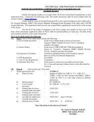
1.8.1 This contract covers the Diversion work <strong>of</strong> 14 Km 220 KV S/C Line from<br />
RISHIKESH-DHARASU & CHAMBA-DHARASU LINE IN TEHRI DAM<br />
Submerged to be done on turnkey basis.<br />
2.3 DETAIL OF WORKS<br />
2.3.1 The scope <strong>of</strong> the works for the above transmission lines covered under this contract<br />
shall be here under :<br />
i) Survey (Preliminary and final) peg marking, preparation <strong>of</strong> pr<strong>of</strong>ile, stub<br />
setting, design & erection <strong>of</strong> all type <strong>of</strong> towers including special structures,<br />
fixing <strong>of</strong> accessories, stringing <strong>of</strong> conductors, stringing <strong>of</strong> earth wire testing<br />
and commissioning <strong>of</strong> erected line etc.<br />
ii) Supply <strong>of</strong> fabricated and galvanized lattice Towers, Galvanised Templates,<br />
Nuts & Bolts, and Washers.<br />
iii) Supply <strong>of</strong> conductor, earthwire, insulators, hardware’s, tower accessories<br />
complete in all respect.<br />
iv) All material related to civil works and constriction <strong>of</strong> foundations & stub<br />
setting, revetment etc.<br />
v) Supply <strong>of</strong> complete material required for completion <strong>of</strong> work.<br />
vi) Arrangement <strong>of</strong> Erection tools.<br />
vii) Taking delivery and proper storage, safe custody <strong>of</strong> various items i.e. tower<br />
parts, bolts & nuts, tower accessories, special structures, conductor, earthwire,<br />
line material, cement etc. and their use in erection and stringing <strong>of</strong><br />
transmission line.<br />
220 KV S/C RISHIKESH-DHARASU & CHAMBA-DHARASU <strong>Transmission</strong> Line<br />
19<br />
http://www.ptcul.org/ten_02_08_08_spcification.pdf
<strong>Power</strong> <strong>Transmission</strong> <strong>Corporation</strong> <strong>of</strong> <strong>Uttarakhand</strong> Ltd.<br />
viii) Arrangement <strong>of</strong> storage cum Erection Insurance Policy for all the line<br />
material for TURNKEY construction <strong>of</strong> transmission lines upto the end <strong>of</strong><br />
completion & Commissioning <strong>of</strong> transmission lines.<br />
ix) Testing and commissioning <strong>of</strong> the lines.<br />
x) Forest case shall be prepared by the contractor.<br />
2.4 COMMENCEMENT OF ACTIVITIES<br />
2.4.1 Commencement <strong>of</strong> the following activities is subject to the prior and specific<br />
approval by the Dy. General Manager( Engg.) PTCUL and receipt <strong>of</strong> approved<br />
data / documents as follows :<br />
(i) Route pr<strong>of</strong>ile Tower spotting data and sag template.<br />
(ii) Foundation Work Stub setting template, foundation designs,<br />
classification <strong>of</strong> foundation.<br />
(iii) Erection <strong>of</strong> tower<br />
(iv) Stringing <strong>of</strong> wires<br />
Quality assurance plan for erection<br />
Stringing charts and stringing.<br />
2.4.2 ENGINEER INCHARGE OF CONTRACT<br />
Dy. General Manager (Engg.) PTCUL shall be Engineer in charge <strong>of</strong> the contract.<br />
The line route, pr<strong>of</strong>iles, classification <strong>of</strong> foundation and other field activities shall<br />
be approved by him. His decision in all field activities shall be final.<br />
2.5 DRAWINGS<br />
2.5.1 The Contractor shall do the construction work strictly in accordance with<br />
approved drawings and no deviation shall be permitted without approval in<br />
writing from the Dy. General Manager (Engg.) PTCUL, if so required.<br />
2.5.2 The Contractor shall submit One set <strong>of</strong> drawings <strong>of</strong> final route survey and<br />
pr<strong>of</strong>ile etc. with necessary details as mentioned in Technical specification for<br />
approval <strong>of</strong> the Dy. General Manager (Engg.) PTCUL. After scrutiny <strong>of</strong> the<br />
drawings by PTCUL and after incorporating all the modifications as mutually<br />
agreed the contractor will submit the final drawings for final approval. PTCUL<br />
will formally approve the tracing and contractor will supply two copies <strong>of</strong><br />
approved drawings.<br />
2.5.3 On the completion <strong>of</strong> erection work, the Contractor will supply to the<br />
Supervising Engineer free <strong>of</strong> cost, the complete as executed drawings <strong>of</strong> the<br />
line(s) showing each and every structure as actually erected, roads, railway<br />
220 KV S/C RISHIKESH-DHARASU & CHAMBA-DHARASU <strong>Transmission</strong> Line<br />
20<br />
http://www.ptcul.org/ten_02_08_08_spcification.pdf
<strong>Power</strong> <strong>Transmission</strong> <strong>Corporation</strong> <strong>of</strong> <strong>Uttarakhand</strong> Ltd.<br />
crossing, all major or small river crossing etc. together with measured spans. At<br />
all deviation points, the angle shall be marked in degrees. All Kutcha and metal<br />
roads, trees structures, ponds and other obstructions etc. within 30 meters on<br />
either side <strong>of</strong> the route shall be clearly indicated. The drawings shall also show<br />
telecommunication or power lines within 30 meters on either side <strong>of</strong> the lines.<br />
The drawings shall be drawn in ink <strong>of</strong> good quality on tracing paper assuming a<br />
scale <strong>of</strong> 20 Mtr. = 1Cm. horizontal and 2 Mtr.=1 Cm vertical.<br />
2.6 COMPLETION PERIOD<br />
2.6.1 The lines shall be completed within 6 months from the date <strong>of</strong> letter <strong>of</strong> award.<br />
The successful bidder shall have to furnish the Bar Chart indicating therein<br />
different activities and their target to achieve the delivery period.<br />
2.6.2 The Contractor would however, endeavor to complete the above transmission<br />
line well in advance <strong>of</strong> the above date as the line is urgently required.<br />
2.7 SPECIAL NOTE<br />
It may be very clearly be noted by all that no modifications in price reduction clause No.<br />
27 <strong>of</strong> Contract form ‘B’ shall be accepted i.e. broadly a price reduction <strong>of</strong> 1/2% per<br />
week subject to maximum <strong>of</strong> 10% <strong>of</strong> the contract value shall be applicable, in case <strong>of</strong><br />
supply not being satisfactory and conforming to specification and as per delivery<br />
schedule it will be at the discretion <strong>of</strong> the corporation to cancel the order besides price<br />
reduction as per clause 27 <strong>of</strong> form ‘B’ from the pending bills or by other means found.<br />
2.8 VARIATION<br />
The quantities given in price schedule are tentative and indicative only and individual<br />
work/supply may vary to any extent according to site position, however total variation<br />
on higher side shall only be +20% <strong>of</strong> the contract value.<br />
2.9 SPECIAL WORKS<br />
The rates for work not included in the Schedules will be decided upon, when any such<br />
necessity arises during the execution <strong>of</strong> the work, by negotiations between the<br />
Supervising Engineer and the Contractor. The contractor shall perform the work on the<br />
terms and conditions as mutually agreed upon.<br />
220 KV S/C RISHIKESH-DHARASU & CHAMBA-DHARASU <strong>Transmission</strong> Line<br />
21<br />
http://www.ptcul.org/ten_02_08_08_spcification.pdf
<strong>Power</strong> <strong>Transmission</strong> <strong>Corporation</strong> <strong>of</strong> <strong>Uttarakhand</strong> Ltd.<br />
2.10 MATERIAL TO BE ARRANGED BY CONTRACTOR<br />
a) This Being a turn key contract all the material including, fabricated galvanized<br />
towers, Zebra conductor, 160 KN and 90 KN insulators 7/3.15 mm earthwire,<br />
tower accessories, accessories <strong>of</strong> ACSR Zebra conductor and 7/3.15 mm<br />
Earthwire, and all the hardware fittings, like Tension/suspension fittings for<br />
ACSR Zebra conductor Tension/suspension clamps for 7/3.15 mm. Earth<br />
wire, shall be arranged by the Contractor. Stone blast, sand, cement, stone<br />
pad M.S. steel bars required for R.C.C. foundation etc. to be used in<br />
foundation work shall be arranged and supplied by the Contractor without any<br />
extra charges to the <strong>Corporation</strong>. Earthing material shall also be arranged by<br />
Contractor.<br />
b) Tools & Plants required for construction <strong>of</strong> the transmission lines at various stages<br />
shall be arranged by the Contractor at his own cost.<br />
c) Mild Steel bars conforming to IS:226 for R.C.C. foundations shall be arranged by<br />
the Contractor. Payment for such bars shall be made as per rates specified in the<br />
price schedule.<br />
d) Any other material, tools and plants etc. besides those are to be arranged by the by<br />
<strong>Corporation</strong> as may be necessary for construction <strong>of</strong> the transmission lines shall be<br />
arranged by the Contractor at his own cost.<br />
e) All the material required under the scope <strong>of</strong> this contract but not covered<br />
specifically in above clause shall be arranged and supplied by the Contractor without<br />
any extra cost to corporation.<br />
2.11 UNACCOUNTABLE WASTAGE<br />
The contractor shall make every effort to minimize the breakage, losses and wastage <strong>of</strong><br />
line material during erection <strong>of</strong> the <strong>Corporation</strong> supplied items. However, the<br />
Contractor will be allowed unaccountable wastage and losses during erection not<br />
exceeding the following values given against each item:<br />
i) Insulator 1.0%<br />
ii) Conductor 1.0%<br />
iii) Hardware Fitting 0.5%<br />
iv) Conductor & Earthwire Accessories 0.5%<br />
The conductor length upto 30 meter will be treated as good conductor lengths. On<br />
completion <strong>of</strong> work, the Contractor will return the balance items over and above<br />
220 KV S/C RISHIKESH-DHARASU & CHAMBA-DHARASU <strong>Transmission</strong> Line<br />
22<br />
http://www.ptcul.org/ten_02_08_08_spcification.pdf
<strong>Power</strong> <strong>Transmission</strong> <strong>Corporation</strong> <strong>of</strong> <strong>Uttarakhand</strong> Ltd.<br />
actually used on each line. Wastage (conductor having length less than 30 meters) shall<br />
also be returned on as is where is basis at <strong>Corporation</strong>’s store at Rishikesh.<br />
The Contractor shall not be required to return to PTCUL empty conductor and Earthwire<br />
drums and shall dispose <strong>of</strong>f the same at his cost.<br />
Permitted Extra Consumption <strong>of</strong> Line Materials<br />
The quantity <strong>of</strong> conductor and Earth wire to be incorporated in the line shall be worked<br />
as per the following norms.<br />
Quantity <strong>of</strong> Conductor = Line Length* as per detailed survey x 3<br />
(For single Circuit Line).<br />
Quantity <strong>of</strong> Earthwire = Line Length* as per detailed survey x no. <strong>of</strong><br />
Earthwire.<br />
For calculation <strong>of</strong> Conductor and Earthwire requirement in hilly stretches, inclined<br />
distance between the towers may be considered instead <strong>of</strong> horizontal distance<br />
(considered for line length). Jumper length will measured separately and will be added<br />
to actual line length.<br />
The Contractor shall make every effort to minimize breakage, losses and wastage <strong>of</strong> the<br />
line materials during erection. However, the Contractor shall be permitted and extra<br />
consumption <strong>of</strong> line materials up to the limits specified.<br />
2.12 PERMITS AND PRIORITIES<br />
2.12.1 Necessary permits, if any, required for the execution <strong>of</strong> the contract shall be arranged<br />
by the Contractor himself. However, the <strong>Corporation</strong> may assist the Contractor for<br />
obtaining permits required for operation <strong>of</strong> the vehicle etc. during construction work<br />
<strong>of</strong> the line.<br />
2.12.2 The <strong>Corporation</strong> shall not be responsible for the delay in execution <strong>of</strong> contract if<br />
permits and priorities are not granted in time.<br />
2.13 RECEIPT OF MATERIAL AT SITE<br />
The contractor shall be responsible for the proper handling and maintenance <strong>of</strong> the<br />
materials received by him from the date <strong>of</strong> their receipts till the end <strong>of</strong> maintenance<br />
period in accordance with the general conditions <strong>of</strong> Contract given Form ‘A’<br />
enclosed.<br />
2.14 STORAGE OF MATERIAL<br />
220 KV S/C RISHIKESH-DHARASU & CHAMBA-DHARASU <strong>Transmission</strong> Line<br />
23<br />
http://www.ptcul.org/ten_02_08_08_spcification.pdf
<strong>Power</strong> <strong>Transmission</strong> <strong>Corporation</strong> <strong>of</strong> <strong>Uttarakhand</strong> Ltd.<br />
2.14.1 The Contractor shall be required to set up stores at suitable place(s) along the route <strong>of</strong><br />
the line to receive and store the materials, within 15 Days <strong>of</strong> the issue <strong>of</strong> Letter <strong>of</strong><br />
Award or as such as the first lot <strong>of</strong> fabricated tower parts for the line received.<br />
2.14.2 The Contractor shall make arrangement to take delivery <strong>of</strong> all the materials and stock<br />
them properly.<br />
2.14.3 Yards and stores for stocking provided by the Contractor shall be open for inspection<br />
by the <strong>Corporation</strong>’s staff as & when desired by the <strong>Corporation</strong>.<br />
2.14.4 The cost <strong>of</strong> handling and storage <strong>of</strong> materials is included in the quoted erection rates<br />
entered in the Price Schedule.<br />
2.14.5 The store shall be kept insured as per provisions <strong>of</strong> this Contract.<br />
2.14.6 The contractor shall keep PTCUL informed about the locations <strong>of</strong> their stores.<br />
2.15 REPLACEMENT AND SHORTAGES<br />
2.15.1 Any material supplied by the Contractor and found defective shall be replaced free <strong>of</strong><br />
cost by the Contractor.<br />
2.15.2 Any erection work done, if done defectively, shall be rectified free <strong>of</strong> cost by the<br />
Contractor.<br />
2.16 ERECTION TOOLS<br />
All the erection tools and plant required for and during the construction <strong>of</strong> the line<br />
shall be arranged by the Contractor at his own cost. The Contractor shall ensure that<br />
tools and plants required for the erection <strong>of</strong> all transmission lines are available with<br />
him sufficiently in advance. No delay in completion period will be accepted if<br />
necessary tools and plants are not arranged by the Contractor in time.<br />
2.17 USE OF ROADS<br />
The Contractor may be allowed to use Private road in connection with the<br />
construction work. The <strong>Corporation</strong> may also help in obtaining permit for using canal<br />
service roads for transport <strong>of</strong> Contractor’s man and materials, wherever possible<br />
under the rules. Any charges levied by the concerned authorities for use <strong>of</strong> Canal<br />
roads etc. shall be borne by the Contractor. This will, however, not be binding on the<br />
<strong>Corporation</strong> and no delay in start or completion <strong>of</strong> work shall be accepted on this<br />
account.<br />
2.18 SAFETY OF STAFF & LABOURERS<br />
The Contractor shall provide and make all necessary arrangements for safety <strong>of</strong> staff<br />
and labourers at site <strong>of</strong> work. The <strong>Corporation</strong> will not, in any way, be responsible for<br />
220 KV S/C RISHIKESH-DHARASU & CHAMBA-DHARASU <strong>Transmission</strong> Line<br />
24<br />
http://www.ptcul.org/ten_02_08_08_spcification.pdf
<strong>Power</strong> <strong>Transmission</strong> <strong>Corporation</strong> <strong>of</strong> <strong>Uttarakhand</strong> Ltd.<br />
any accident minor, major or fatal, to any person at the site <strong>of</strong> work or for any<br />
damage arising there from during the erection, which shall be contractor’s<br />
responsibility. The staff insurance charges, if any, shall also be borne by the<br />
Contractor.<br />
2.19 INSPECTION & INSPECTION CERTIFCATE<br />
2.19.1 PTCUL, through its duly authorized representative shall have at all reasonable<br />
times access to the contractor’s premises, stores or works and shall have the<br />
power, at all reasonable times to inspect and examine the materials and<br />
workmanship <strong>of</strong> the works during its erection. They will be given all help by the<br />
contractor for carrying out such inspection.<br />
2.19.2 The inspection by PTCUL/Supervising Engineer or their authorized<br />
representative and issue <strong>of</strong> inspection certificate thereon shall in no way limit<br />
the liabilities and responsibilities <strong>of</strong> the Contractor in respect <strong>of</strong> agreed quality<br />
assurance programme forming a part <strong>of</strong> the Contract.<br />
2.20 WAY LEAVE & TREE CUTTING & OTHER CLEARANCE<br />
2.20.1 Any Right <strong>of</strong> way, which may be required by the Contractor, shall be arranged<br />
by PTCUL, except for approach roads, on intimation from the Contractor after<br />
submission <strong>of</strong> the final alignment, proposals for Right <strong>of</strong> Way, shall be<br />
submitted by the contractor well in advance to avoid delay. Permission will be<br />
obtained by PTCUL within reasonable time, for which due notice shall be given<br />
by the Contractor.<br />
2.20.2 Tree cutting should be avoided as far as possible. However, if the tree cutting is<br />
necessary it shall be done by the contractor. For this purpose, complete details<br />
<strong>of</strong> the type and size (diameter / circumference) and other relevant/ required<br />
details with number <strong>of</strong> trees alongwith name owner there<strong>of</strong>, duly verified by<br />
local district/ Revenue authorities shall also be submitted by the Contactor<br />
within 30 days <strong>of</strong> the final survey.<br />
2.20.3 PTCUL shall not be held responsible for any claim on account <strong>of</strong> damage done<br />
by the Contractor or his gangs to trees, crops or other property without authority<br />
form PTCUL.<br />
2.20.4 In case <strong>of</strong> anticipated damage <strong>of</strong> crops, the details <strong>of</strong> fruits bearing trees and<br />
other crops, area, plot numbers and name <strong>of</strong> owners etc. duly verified by<br />
district/ revenue authorities shall be submitted by the Contractor well in time.<br />
2.20.5 In the event <strong>of</strong> any obstruction being encountered from the local villagers or<br />
authorities the Contractor shall immediately notify the <strong>Corporation</strong>, who shall<br />
take such steps as may be necessary to clear the obstruction. The Contractor or<br />
his representatives or gangs shall immediately report to PTCUL any case <strong>of</strong><br />
obstruction which cannot be settled amicably. They will not adopt any<br />
antagonistic attitude towards the local people they come in contact with.<br />
220 KV S/C RISHIKESH-DHARASU & CHAMBA-DHARASU <strong>Transmission</strong> Line<br />
25<br />
http://www.ptcul.org/ten_02_08_08_spcification.pdf
<strong>Power</strong> <strong>Transmission</strong> <strong>Corporation</strong> <strong>of</strong> <strong>Uttarakhand</strong> Ltd.<br />
2.20.6 Payment <strong>of</strong> compensation towards the clearance etc. will be the responsibility <strong>of</strong><br />
the contractor.<br />
2.20.7 The Contractor shall take all possible steps to see that unavoidable damage to<br />
standing crops etc. is kept to a minimum.<br />
2.20.8 FOREST CASE<br />
Contractor shall prepare Forest Case in Civil, Private Forest Land and his scope<br />
will be preparation <strong>of</strong> case, all efforts approvals from Revenue, Forest or any<br />
Government authorities will be in scope <strong>of</strong> Contractor. Any compensation to<br />
Forest Authorities will be disbursed by PTCUL. The crop compensation shall be<br />
Contractor’s responsibility.<br />
2.20.9 The Contractor shall prepare necessary proposals including supply <strong>of</strong><br />
necessary data and documents required in connection with the clearance relating<br />
to the following :<br />
a) PTCC Clearance.<br />
b) Clearance from Air Port / Fields<br />
2.20.10 The Contractor shall inform PTCUL about the places where there is any<br />
problem, including Forest as sufficiently in advance, so that required clearance<br />
can be arranged in time The board shall not be held responsible for any claim on<br />
account <strong>of</strong> damage done by the Contractor or his gangs to trees, Crops or other<br />
property without authority from the Supervising Engineer. The Supervising<br />
Engineer in this contract shall be DGM(Project), for this purpose.<br />
2.20.11 The Contractor shall take all possible steps to ensure that crops, damages etc. is<br />
kept to a minimum and in the event <strong>of</strong> extensive damage to ripe or partially<br />
developed crops.<br />
2.21 COMPLIANCE WITH REGULATIONS<br />
2.21.1 Unless otherwise specified all work shall be carried out in accordance with the<br />
Indian Electricity Act, 1910, Indian Electricity rules 1956 & The Indian<br />
Electricity Act 2003 with any amendments or revisions there<strong>of</strong>, which may be<br />
issued during the currency <strong>of</strong> the contract and the requirement <strong>of</strong> any other<br />
Regulation and Act in India to which the corporation may be subjected to.<br />
2.21.2 All power / communication line, or other important road crossing etc. or routing<br />
the line through air field region shall conform to the relevant rules and<br />
procedures laid down by railway, communication, Aviation or other concerned<br />
authorities.<br />
2.21.3 The Contractor shall also be governed by the acts relating to conservation <strong>of</strong><br />
forest, while routing the transmission line.<br />
220 KV S/C RISHIKESH-DHARASU & CHAMBA-DHARASU <strong>Transmission</strong> Line<br />
26<br />
http://www.ptcul.org/ten_02_08_08_spcification.pdf
<strong>Power</strong> <strong>Transmission</strong> <strong>Corporation</strong> <strong>of</strong> <strong>Uttarakhand</strong> Ltd.<br />
i) Necessary care should be taken to avoid delay on account <strong>of</strong> obtaining forest<br />
clearance.<br />
ii) Supervise the quality assurance programme implementations at all stages <strong>of</strong><br />
the works.<br />
2.22 TRAINING OF CORPORATION’S STAFF<br />
The <strong>Corporation</strong> reserves the right to attach its own staff comprising <strong>of</strong> engineer and<br />
subordinates with the contractor’s erection staff for the purpose <strong>of</strong> gaining experience<br />
and the Contractor shall extend all facilities for this purpose. The contractor shall not<br />
however be required to incur any expenditure on this account.<br />
2.23 RESPONSIBILITY OF THE CONTRACTOR & COMPLETENESS<br />
2.23.1 The Contractor shall guarantee and be entirely responsible for the execution <strong>of</strong><br />
the Contract in accordance with the General Conditions <strong>of</strong> Contract Form ‘A’<br />
Special Conditions, <strong>Specification</strong>s, annexures and Schedules, appendices, other<br />
documents and all clauses <strong>of</strong> this contract.<br />
2.23.2 The Contractor shall guarantee and be entirely responsible for taking delivery <strong>of</strong><br />
all materials, storage, cartage, proper handling and storage <strong>of</strong> all materials at site<br />
testing and commissioning and maintenance <strong>of</strong> the said line, insurance during<br />
storage till the line is taken over by the Supervising Engineer.<br />
2.23.3 He shall further guarantee and be responsible for the quality and workmanship<br />
<strong>of</strong> completed work, conformity <strong>of</strong> all works to the approved designs and<br />
drawings, and their proper erection within the guaranteed completion and<br />
maintenance period, till the line is taken over by the <strong>Corporation</strong>.<br />
2.23.4 The Contractor shall be responsible for the timely submission <strong>of</strong> pr<strong>of</strong>iles, type<br />
<strong>of</strong> foundations etc, since the erection <strong>of</strong> the lines is related with them. As such<br />
he shall also be responsible for obtaining the approval <strong>of</strong> pr<strong>of</strong>iles, types <strong>of</strong><br />
foundation etc./ within the schedule time. In this connection, if necessary he will<br />
depute his representative to sort out the matter with the Supervising Engineer.<br />
2.23.5 The <strong>Corporation</strong> shall have the right to require the Contractor to make any<br />
change in the erection practices, which may be necessary in the opinion <strong>of</strong><br />
PTCUL/Supervising Engineer to make the towers and other materials and work<br />
conforming to the provisions and contents <strong>of</strong> the specification, without extra<br />
cost <strong>of</strong> the <strong>Corporation</strong>.<br />
2.23.6 Approval by PTCUL or by any authorized representative <strong>of</strong> the <strong>Corporation</strong> <strong>of</strong><br />
the Contractor’s or Sub- Contractor’s drawings, material or <strong>of</strong> other parts <strong>of</strong><br />
work involved in the contract, or <strong>of</strong> tests carried out either by the Contractor or<br />
220 KV S/C RISHIKESH-DHARASU & CHAMBA-DHARASU <strong>Transmission</strong> Line<br />
27<br />
http://www.ptcul.org/ten_02_08_08_spcification.pdf
<strong>Power</strong> <strong>Transmission</strong> <strong>Corporation</strong> <strong>of</strong> <strong>Uttarakhand</strong> Ltd.<br />
by the Sub- Contractor or <strong>Corporation</strong> shall not relieve the Contractor <strong>of</strong> any<br />
part <strong>of</strong> the Contractor’s obligations <strong>of</strong> meeting all the requirement <strong>of</strong> the<br />
specifications.<br />
2.23.7 Any work performed prior to the approval <strong>of</strong> drawings, tests etc. will be at<br />
Contractor’s risk.<br />
2.23.8 Contractor shall submit revetment drawings with Supervising Engineer for<br />
approval by DGM(Engg.) and work shall be carried out as per approved<br />
drawings. Any deviation from same shell be at contactor risk. All revetment<br />
drawing shell be developed by the contactor.<br />
2.24 PROJECT MONITORING<br />
2.24.1 After the award <strong>of</strong> contract, the Contractor in consultation with PTCUL /<br />
Supervising Engineer shall prepare a detailed time schedule for each activity<br />
and relating various activities with each other in chronological sequence.<br />
2.24.2 The time schedule shall be submitted in the following formats:<br />
a) Bar Chart giving broad schedules <strong>of</strong> main activities such as finalization <strong>of</strong><br />
designs and drawings, tower testing, procurement <strong>of</strong> materials, manufacture<br />
and supply <strong>of</strong> tower parts, construction <strong>of</strong> foundations erection <strong>of</strong> towers,<br />
erection <strong>of</strong> line material, stringing and testing commissioning. In this chart,<br />
both commencement and completion dates <strong>of</strong> each activity are to indicated.<br />
2.24.2.1 During the execution <strong>of</strong> the Contract, the Contractor shall furnish the following<br />
reports to PTCUL / Supervising Engineer:<br />
a) Weekly progress report <strong>of</strong> various activities <strong>of</strong> erection <strong>of</strong> line as well as<br />
receipt <strong>of</strong> various materials at site, indicating actual progress during the<br />
fortnight as well as cumulative.<br />
b) Monthly progress report for the designs and engineering activities giving<br />
scheduled and actual progress <strong>of</strong> the submission, scrutiny and approval <strong>of</strong><br />
the various drawings, pr<strong>of</strong>iles and charts etc.<br />
c) Any other progress report daily/weekly as desired by the Purchaser.<br />
2.24.3 The format for the above progress reports shall be as per enclosed Annexure.<br />
2.24.3.1 Besides above, a periodical review meeting between Contractor and<br />
Supervising Engineer or his authorized representative shall be held to analyze<br />
the Schedule and actual progress, targets for the next period and to sort out<br />
bottlenecks, if any. The Contractor will attend the above meeting along with<br />
necessary information in respect <strong>of</strong> supply and erection activities.<br />
220 KV S/C RISHIKESH-DHARASU & CHAMBA-DHARASU <strong>Transmission</strong> Line<br />
28<br />
http://www.ptcul.org/ten_02_08_08_spcification.pdf
<strong>Power</strong> <strong>Transmission</strong> <strong>Corporation</strong> <strong>of</strong> <strong>Uttarakhand</strong> Ltd.<br />
2.24.4 In case the Contractor repeated fails to givethe above progress reports or if the<br />
progress <strong>of</strong> supplies or works falls behind the mutually agreed work<br />
schedule/bar chart by more than three weeks, PTCUL may initiate punitive<br />
action against the Contractor and may also initiate action to get the work done<br />
by another firm,without any further delay, completely at the cost and risk <strong>of</strong> the<br />
Contractor<br />
3 SCHEDULE OF MILESTONES AND TERMS OF PAYMENT<br />
3.1 The payment <strong>of</strong> supplies and works shall be made in slabs as per milestones as described<br />
below. Completion <strong>of</strong> key activities shall be considered as milestones as listed below<br />
and for each milestone a certain percentage <strong>of</strong> the total payment shall be payable, as<br />
tabulated below :<br />
Sl.<br />
Activity/Name <strong>of</strong> Milestone<br />
Percentage <strong>of</strong> the total amount<br />
No.<br />
payable<br />
1 Mobilisation advance 10%<br />
2 Detailed survey, Pr<strong>of</strong>iling and Preparation <strong>of</strong><br />
forest case<br />
3 Supply <strong>of</strong> stubs and templates 5%<br />
4 Casting <strong>of</strong> foundations 10%<br />
5 Supply <strong>of</strong> towers 20%<br />
6 Supply <strong>of</strong> conductor and hardware fittings 20%<br />
7 Tower Erection 20%<br />
8 Stringing, testing and commissioning 10%<br />
5%<br />
3.2 The full payments for the mobilization advance, detailed survey, pr<strong>of</strong>iling survey,<br />
pr<strong>of</strong>iling, preparation <strong>of</strong> forest case, supply <strong>of</strong> stubs and templates, stringing, testing and<br />
commissioning shall be made once for each milestone.<br />
3.3 The payments for he other milestones shall be made in slabs <strong>of</strong> 20% i.e. when 20% <strong>of</strong><br />
the work <strong>of</strong> the milestone is completed, then 20% <strong>of</strong> the amount allocated for that<br />
milestone shall become payable.<br />
220 KV S/C RISHIKESH-DHARASU & CHAMBA-DHARASU <strong>Transmission</strong> Line<br />
29<br />
http://www.ptcul.org/ten_02_08_08_spcification.pdf
<strong>Power</strong> <strong>Transmission</strong> <strong>Corporation</strong> <strong>of</strong> <strong>Uttarakhand</strong> Ltd.<br />
3.4 The supply <strong>of</strong> towers shall commence after 20% <strong>of</strong> the total number <strong>of</strong> foundations are<br />
cast and payments for tower supply shall be made when 20% <strong>of</strong> the total number <strong>of</strong><br />
complete towers are received.<br />
3.5 Similarly, the supply <strong>of</strong> conductor and hardware shall begin when 20% <strong>of</strong> the total<br />
numbers <strong>of</strong> complete towers have been erected.<br />
3.6 90% <strong>of</strong> the amounts payable as per the above milestones, whether for work or supply,<br />
shall be made to the Contractor against monthly running bills and balance 10% after<br />
expiry <strong>of</strong> maintenance period. The balance amounts shall be paid as per the SBD.<br />
5.0 TECHNICAL CONDITIONS OF CONTRACT<br />
1.0 PROJECT DESCRIPTION<br />
1.0.0 The <strong>Power</strong> <strong>Transmission</strong> <strong>Corporation</strong> <strong>of</strong> <strong>Uttarakhand</strong> Ltd proposes the<br />
Diversion work <strong>of</strong> 14 Km 220 KV S/C Line from RISHIKESH-DHARASU &<br />
CHAMBA-DHARASU LINE IN TEHRI DAM Submerged area to be done on<br />
turnkey basis.<br />
as mentioned in the Price Schedule and this section <strong>of</strong> the Contract covers the<br />
technical specification in connection with the erection <strong>of</strong> transmission lines on<br />
turnkey – basis.<br />
1.0.1 The approximate quantities <strong>of</strong> tower extension, templates, accessories etc. are given<br />
in the Bid Price Schedule. The exact quantities will be worked out after detailed<br />
survey.<br />
1.1 CLIMATIC CONDITIONS<br />
The line passes through an area where the climatic and isoceraunic conditions<br />
are as given below:<br />
LOCATION - RISHIKESH-DHARASU & CHAMBA-DHARASU<br />
i) Max ambient Temp 50 0 C.<br />
ii) Minimum Ambient Temp. 5 0 C<br />
iii) Relative Humidity 100% Max, 10% Min.<br />
iv) No. <strong>of</strong> Monsoon month June to September<br />
v) Average annual rainfall 2200 mm<br />
220 KV S/C RISHIKESH-DHARASU & CHAMBA-DHARASU <strong>Transmission</strong> Line<br />
30<br />
http://www.ptcul.org/ten_02_08_08_spcification.pdf
<strong>Power</strong> <strong>Transmission</strong> <strong>Corporation</strong> <strong>of</strong> <strong>Uttarakhand</strong> Ltd.<br />
vi) Seismic Level 0.139<br />
viii) Wind Zone 4<br />
1.2 MATERIAL AND WORKMAINSHIP<br />
1.2.0 Unless otherwise specified, all material used shall be <strong>of</strong> out door type, <strong>of</strong> the<br />
best quality and workmanship, capable <strong>of</strong> satisfactory operation under the<br />
operating and atmospheric conditions specified. Unless otherwise specified,<br />
they shall conform in all respect to the requirement <strong>of</strong> the latest edition <strong>of</strong> the<br />
relevant Indian Standard <strong>Specification</strong> on that behalf. Wherever Indian Standard<br />
<strong>Specification</strong>s have not been formulated British Standard <strong>Specification</strong> or IEC<br />
shall apply.<br />
1.2.1 The material is to be arranged by the Contractor, this being a turnkey project.<br />
1.2.2 All materials shall be erected after being approved and passed by the<br />
Supervising Engineer. The erection <strong>of</strong> the line shall be done according to the<br />
best practices being followed in erection <strong>of</strong> High Voltage Line with the best<br />
erection equipments so as to give satisfactory result.<br />
2 PTCUL’s Environment and Social Safeguard Policy and its Implementation.<br />
6.1.1 Non judicious and unwarranted use <strong>of</strong> natural resources albeit in man’s quest for<br />
development and growth <strong>of</strong> mankind through industrialization has had considerable<br />
impact on the environment and society. As a result, environmental and social issues<br />
have emerged as focal points <strong>of</strong> global debate. PTCUL’s activities by their<br />
inherent nature and flexibility have negligible impacts on environment. PTCUL has<br />
evolved its Environmental and Social Policy and Procedures (ESPP).<br />
6.1.2 Objectives <strong>of</strong> the environmental and social policy <strong>of</strong> PTCUL:<br />
• Sustainable use and conservation <strong>of</strong> natural resources.<br />
• Efficient and safe technology practices.<br />
• Minimiztion <strong>of</strong> losses in energy during transmission.<br />
• Minimization <strong>of</strong> social impacts such as displacement <strong>of</strong> people and adverse effects on<br />
their livelihood.<br />
6.1.3 The key principles <strong>of</strong> PTCUL Environmental and Social Policy are :<br />
220 KV S/C RISHIKESH-DHARASU & CHAMBA-DHARASU <strong>Transmission</strong> Line<br />
31<br />
http://www.ptcul.org/ten_02_08_08_spcification.pdf
<strong>Power</strong> <strong>Transmission</strong> <strong>Corporation</strong> <strong>of</strong> <strong>Uttarakhand</strong> Ltd.<br />
ii)<br />
iii)<br />
iv)<br />
Avoidance <strong>of</strong> environmentally and socially sensitive areas while planning project<br />
activities.<br />
Minimization <strong>of</strong> impacts when project activities occur in environmentally and<br />
socially sensitive areas.<br />
Mitigation <strong>of</strong> any unavoidable adverse impacts arising out <strong>of</strong> its projects.<br />
1.0 Basic issues to be kept in mind while carrying out construction activities are to<br />
i) Avoid socially sensitive areas with regard to human habitations and areas <strong>of</strong><br />
cultural significance.<br />
ii)<br />
iii)<br />
iv)<br />
Secure the interest <strong>of</strong> people affected by PTCUL’s projects.<br />
Involve local people affected by transmission line projects as per requirement and<br />
suitability.<br />
Consult affected people in decisions having implication to them if considered<br />
necessary.<br />
v) Apply, efficient and safe technology/practices.<br />
vi)<br />
vii)<br />
viii)<br />
ix)<br />
Keep abreast <strong>of</strong> all potential dangers to people’s health, occupational safety and<br />
safety <strong>of</strong> environmental and the respective mitigatory measures.<br />
Establish preventive mechanisms to guarantee safety.<br />
Mitigation measures in case <strong>of</strong> accidents.<br />
Avoid unwarranted cutting <strong>of</strong> trees in forest area.<br />
1.1 While constructing the lines through forest stretches the Contractor will provide<br />
alternate fuel to its employee e.g. working labours/supervisors etc. in order to avoid<br />
cutting <strong>of</strong> forest woods.<br />
1.2 Contractor will ensure safety to the wild life, during working/camping near to the<br />
National park.<br />
1.3 Contractor during construction <strong>of</strong> lines in agricultural fields will ensure minimum<br />
damages to the crops, trees, bunds, irrigation etc. If the same is un-avodiable, the<br />
decision <strong>of</strong> Engineer in-charge shall be final.<br />
1.4 The waste/excess material/debris should be removed form the construction site<br />
including agricultural field, forest stretches, river etc. immediately after construction<br />
work in a safe manner.<br />
220 KV S/C RISHIKESH-DHARASU & CHAMBA-DHARASU <strong>Transmission</strong> Line<br />
32<br />
http://www.ptcul.org/ten_02_08_08_spcification.pdf
<strong>Power</strong> <strong>Transmission</strong> <strong>Corporation</strong> <strong>of</strong> <strong>Uttarakhand</strong> Ltd.<br />
1.5 The Contractor will ensure least disturbance to the hill slope and natural drainage so<br />
as to avoid soil erosion. Natural drainage in plain area if disturbed to be trained to the<br />
satisfaction <strong>of</strong> Engineer in-charge.<br />
1.6 As far as possible existing path/kutchha road/approach shall be used for the<br />
construction.<br />
1.7 The Contractor will ensure supply <strong>of</strong> stone chips/sand form authorized/approved<br />
quarry areas.<br />
1.8 No waste materials or by-products shall be released into the environment where they<br />
or the products <strong>of</strong> their combustion, decomposition or any <strong>of</strong> the products formed<br />
after their interaction with the environment may damage the soil, water bodies,<br />
atmosphere or any other element <strong>of</strong> the environment or have any harmful effects on<br />
the health <strong>of</strong> human beings, flora or fauna.<br />
1.9 The Contractor shall take suitable steps to keep the noise levels within acceptable<br />
limits so as not to disturb human beings or animals.<br />
1.10 All precautions shall be taken by the Contractor to avoid the occurrence <strong>of</strong> any forest<br />
fire.<br />
1.11 All precautions shall be taken by the Contractor to prevent wastage <strong>of</strong> water.<br />
1.12 All precautions shall be taken by the Contractor to prevent the wastage <strong>of</strong> energy or<br />
fuel.<br />
1.13 The Contractor shall make provisions for safe and proper relocation <strong>of</strong> the excavated<br />
soil.<br />
1.14 The Contractor shall ensure proper documentation <strong>of</strong> above.<br />
1.15 Relevant regulatory and legal aspects <strong>of</strong> environmental issues shall have to be borne<br />
in mind.Techno-Economic Clearance by CEA under Electricity (Supply) Act 1948<br />
and Forest clearance under the Forest (Conservation) Act, 1980 Are mandatory<br />
environmental requirements <strong>of</strong> the Nation & State <strong>of</strong> <strong>Uttarakhand</strong> which shall have<br />
to be obtained..Prescriptive framework (National & <strong>Uttarakhand</strong> State) in the form<br />
<strong>of</strong> Constitutional Guarantees and Applicable Legislations shall have to be fully<br />
complied with. As also will be the relevant policies such as the National<br />
Conservation Strategy and Draft policy Statement on Environment and<br />
Development, 1992 and draft policy statement fro abatement <strong>of</strong> pollution 1992.In<br />
case any National Park , reserve forest , wildlife sanctuary or biosphere reserve are<br />
encountered ,the approval <strong>of</strong> the Hon’ble Supreme Court approval for the effected<br />
forest land in above Wild Life Sanctuaries shall be required.<br />
220 KV S/C RISHIKESH-DHARASU & CHAMBA-DHARASU <strong>Transmission</strong> Line<br />
33<br />
http://www.ptcul.org/ten_02_08_08_spcification.pdf
<strong>Power</strong> <strong>Transmission</strong> <strong>Corporation</strong> <strong>of</strong> <strong>Uttarakhand</strong> Ltd.<br />
1.16 The laws and regulations pertaining to social aspects will have to be followed.<br />
Notification under Section 29 <strong>of</strong> the Electricity (Supply) Act, 1948, (Public<br />
Consultation Components), Rights <strong>of</strong> Way and Compensation Under Electricity<br />
Laws and Provisions Under Land Acquisition Act, 1894, as amended in 1984 are<br />
mandatory requirements (National & <strong>Uttarakhand</strong> State) ..Prescriptive Framework<br />
(National & <strong>Uttarakhand</strong> State) such as Constitutional Guarantees, State-wide Laws<br />
and Policies Relating to Land Acquisition and Issues <strong>of</strong> R&R – Rehabilitation Draft<br />
policy December 1998 (THDC) must be complied with. Relevant policies regarding<br />
Draft <strong>Uttarakhand</strong> State Draft policy for Rehabilitation <strong>of</strong> Persons Displaced as a<br />
Consequence <strong>of</strong> Acquisition <strong>of</strong> Land, Draft NGO Position Paper, in response to the<br />
above, Definition <strong>of</strong> Projects affected persons (PAPs) and Nature and extent <strong>of</strong><br />
entitlements have to be considered and complied with<br />
1.17 COMPLETION SCHEDULE<br />
1.17.0 The time and date <strong>of</strong> completion <strong>of</strong> the work as stipulated in the special<br />
conditions <strong>of</strong> contract Part (II) and accepted by the bidder shall be deemed to<br />
be the essence <strong>of</strong> the Contract. The contractor shall so organize his resources<br />
and perform his work as to complete it not later than the date agreed to. The<br />
time for completion <strong>of</strong> the work contracted for shall be reckoned from the date<br />
<strong>of</strong> Letter <strong>of</strong> award.<br />
1.17.1 The contractor shall submit the Bar and PERT Charts for work and supply <strong>of</strong><br />
material along with his <strong>of</strong>fer. Completion Schedule <strong>of</strong> Individual activity is<br />
not binding provided the <strong>Transmission</strong> Line is completed within the<br />
Completion Time.<br />
1.17.2 The contractor shall submit daily progress reports on the pr<strong>of</strong>orma specified<br />
by PTCUL and also the detailed weekly progress report to the supervising<br />
engineer each week.<br />
1.17.3 The contractor shall submit the detailed BAR CHART and PERT NETWORK<br />
within the time frame agreed above consisting <strong>of</strong> adequate number <strong>of</strong><br />
activities covering various key phases <strong>of</strong> the work such as design,<br />
procurement, manufacturing, shipment and / or field erection activities within<br />
fifteen days (15 days) after the signing <strong>of</strong> Contract. This net work shall also<br />
indicate the inter-phase facilities to be provided by the Purchaser and the dates<br />
by which such facilities are needed, contractor shall discuss the network so<br />
submitted with the Purchaser and the outcome <strong>of</strong> discussions shall form a part<br />
<strong>of</strong> the Contract to be signed within thirty days from the date <strong>of</strong> acceptance <strong>of</strong><br />
notification.<br />
1.17.4 The above BAR CHART and PERT NETWORK shall be reviewed and<br />
periodical review report shall be submitted by the contractor as directed by<br />
PTCUL.<br />
1.18 RESPONSIBILITY OF THE CONTRACTOR<br />
220 KV S/C RISHIKESH-DHARASU & CHAMBA-DHARASU <strong>Transmission</strong> Line<br />
34<br />
http://www.ptcul.org/ten_02_08_08_spcification.pdf
<strong>Power</strong> <strong>Transmission</strong> <strong>Corporation</strong> <strong>of</strong> <strong>Uttarakhand</strong> Ltd.<br />
1.18.0 The contractor shall guarantee and be responsible for the quality and<br />
workmanship <strong>of</strong> all material and complete work, correct designs and drawings<br />
and their accuracy, conformity <strong>of</strong> all work to the approved design and<br />
drawings testing <strong>of</strong> equipment and their correct delivery and/or their erection<br />
within the guaranteed completion period.<br />
1.18.1 The purchaser shall have the right to require the contractor to make any<br />
change in the design which may be necessary in the opinion <strong>of</strong> PTCUL, to<br />
make the equipment and work conform to the provisions and contents or<br />
specification without extra cost to the Purchaser. Approval by PTCUL, or by<br />
the representative <strong>of</strong> the Purchaser <strong>of</strong> the contractor’s drawings, material or <strong>of</strong><br />
other part <strong>of</strong> work involved in the contract or <strong>of</strong> test carried out either by the<br />
contractor or by Purchaser, shall not relieve the contractor <strong>of</strong> any part <strong>of</strong> the<br />
contractor’s obligations <strong>of</strong> meeting all the requirement <strong>of</strong> the specifications or<br />
<strong>of</strong> the responsibility for the correctness <strong>of</strong> the contractor’s design and<br />
drawings. Any manufacture or other work performed prior to the approval <strong>of</strong><br />
drawing and test will be at contractor’s risk.<br />
1.18.2 The contractor shall guarantee and be responsible for the design, fabrication,<br />
galvanizing and testing, packing, insurance during transit, dispatch <strong>of</strong> all<br />
material to destination. Proper handling, cartage and storage <strong>of</strong> all line<br />
materials at site in their custody, line erection setting to work <strong>of</strong> the said<br />
transmission line.<br />
1.19 QUANTITY<br />
The quantities mentioned in this specification are purely tentative and can vary to any<br />
extent on either side as per site requirements <strong>of</strong> the purchaser at the unit price<br />
mentioned in Price Schedule subject to maximum variation <strong>of</strong> +20% <strong>of</strong> total contract<br />
value on the higher side .<br />
1.20 PROGRESS REPORT<br />
In addition to the daily progress reports, detailed weekly reports showing the actual<br />
progress made in the receipt <strong>of</strong> materials/equipment by the contractor and completion<br />
<strong>of</strong> various works shall be regularly submitted to purchaser, starting one month from<br />
the date <strong>of</strong> CONTRACT.<br />
1.21 TRAINING TO PURCHASER’S STAFF<br />
The purchaser reserve the right to attach its own staff comprising <strong>of</strong> engineers and/<br />
or subordinates in the contractor’s work or with the erection staff for the purpose <strong>of</strong><br />
gaining experience, contractor shall extend all necessary facilities for this purpose.<br />
However, the contractor shall not incur any expenditure on this account.<br />
7.0 DEVIATION FROM SPECIFICATION<br />
220 KV S/C RISHIKESH-DHARASU & CHAMBA-DHARASU <strong>Transmission</strong> Line<br />
35<br />
http://www.ptcul.org/ten_02_08_08_spcification.pdf
<strong>Power</strong> <strong>Transmission</strong> <strong>Corporation</strong> <strong>of</strong> <strong>Uttarakhand</strong> Ltd.<br />
This specification is mainly for the guidance <strong>of</strong> the manufacturer. These requirements<br />
<strong>of</strong> necessity include some specific elements <strong>of</strong> construction and material but are not<br />
intended to preclude ingenuity <strong>of</strong> design are improvement. If the bidder proposes any<br />
deviation from this specification, these will be considered, provided they are necessary<br />
either to improve the utility, performance and efficiency or to ensure overall economy.<br />
This will be clearly and explicitly explained in the tender. Such variations are also<br />
brought out clause by clause in the prescribed schedule.<br />
7.0 DELIVERY SCHEDULE AND WORK SCHEDULE<br />
The delivery & work shall be quoted specifically and explicitly for each complete item<br />
separately.<br />
8.0 DRAWINGS<br />
The contractor shall design & give the following to PTCUL for approval.<br />
) Hardware & Accessories Drawings.<br />
i) Tower Footing Protection Drawings.<br />
Contractor shall supply the material only after approval <strong>of</strong> drawing and after<br />
inspection <strong>of</strong> authorized representative <strong>of</strong> PTCUL or after waiver <strong>of</strong> inspection.<br />
The bidder on the basis <strong>of</strong> structural drawings shall prepare bill <strong>of</strong> material and<br />
shop drawings at his own and get it approved from PTCUL before fabrication<br />
The contractor shall develop the Tower footing protection drawings and submit to<br />
D.G.M. (Engg.) for approval duly recommended by D.G.M.(PI).<br />
9.0 TYPE TESTS / TYPE TEST CHARGES<br />
The <strong>of</strong>fered equipment must have been fully type tested as per relevant ISS and / or<br />
any other specified international standards. Photocopy <strong>of</strong> such type test reports /<br />
certificates must be submitted along with the tender bid. Fresh Type Test if required<br />
will be paid by PTCUL.<br />
11.0 QUALITY OF WORK<br />
The work executed by Contractor shall be strictly as per electricity safely rules and<br />
regulation and in no case shall be inferior in quality <strong>of</strong> work carried out by various<br />
electricity Boards / <strong>Corporation</strong>s in India.<br />
12.0 DEVIATIONS: - The <strong>of</strong>fer should be strict in accordance with the conditions,<br />
specifications and other requirements mentioned in the tender specification<br />
documents. No deviations are permitted except under special circumstances. If the<br />
Bidder wish to depart from specifications in any way, he must draw specific<br />
attention to such departure. All such deviations shall specifically be indicted in<br />
220 KV S/C RISHIKESH-DHARASU & CHAMBA-DHARASU <strong>Transmission</strong> Line<br />
36<br />
http://www.ptcul.org/ten_02_08_08_spcification.pdf
<strong>Power</strong> <strong>Transmission</strong> <strong>Corporation</strong> <strong>of</strong> <strong>Uttarakhand</strong> Ltd.<br />
the prescribed form submitted along with the tender documents, otherwise it will<br />
be presumed that there are no deviations and this interpretation will be binding<br />
upon the Bidder. PTCUL is, however, not bound to accept all or any deviations as<br />
mentioned in such schedules. Bidder are also advised not to enclose their own<br />
standard or printed terms and conditions for sale etc. as the same shall not be<br />
considered.<br />
220 KV S/C RISHIKESH-DHARASU & CHAMBA-DHARASU <strong>Transmission</strong> Line<br />
37<br />
http://www.ptcul.org/ten_02_08_08_spcification.pdf
<strong>Power</strong> <strong>Transmission</strong> <strong>Corporation</strong> <strong>of</strong> <strong>Uttarakhand</strong> Ltd.<br />
SECTION - 2<br />
TOWERS<br />
1.1 SCOPE<br />
1.1.1 The scope <strong>of</strong> Bidder covers erection and supply <strong>of</strong> conductor, insulators,<br />
earthwire & tower including ( fabrication, galvanization and testing <strong>of</strong> towers<br />
) tower foundations, design, fabrication, testing and supply <strong>of</strong> all hardware<br />
accessories & fittings, dispatch, packing & forwarding, transportation. FOR<br />
delivery & unloading at destination stores <strong>of</strong> all Galvanized stub templates,<br />
including bolts, nuts & washers, hangers, D-shackle & all type <strong>of</strong> tower<br />
accessories like phase plate, number plate, danger plate, circuit plate, anticlimbing<br />
devices, including tower earthing.<br />
1.1.2 Steel required for 220 KV S/C <strong>Transmission</strong> line towers shall be procured and<br />
used by the Contractor.<br />
1.1.3 All other material such as Zinc for Galvanising, bolts, nuts, washers,<br />
D-shackles, hangers, links, danger plates, phase plate, number plate etc<br />
required for tower is included in the bidder’s scope <strong>of</strong> supply.<br />
1.1.4 The material to be supplied on FOR Destination Store as covered in this<br />
section shall be designed, manufactured and tested as per the requirement<br />
specified. The bidder is required to quote ex-work price, Excise Duty, Taxes /<br />
Levies, Packing and Forwarding cost, cost <strong>of</strong> transportation and material from<br />
his works/ factory to destination stores.<br />
1.2 STANDARDS<br />
1.2.1 Except where otherwise specified or implied, the design, manufacturing,<br />
fabrication, galvanization and testing <strong>of</strong> towers and tower accessories shall<br />
conform to the provisions <strong>of</strong> IS:802-1995 (Part I, II, III).<br />
1.2.2 The Indian Standard <strong>Specification</strong> (IS) mentioned below as amended upto<br />
date shall be applicable to the materials and process used in the manufacture<br />
<strong>of</strong> towers and tower accessories.<br />
1. IS: 209-1997 <strong>Specification</strong> for zinc.<br />
2. IS: 269-1989 Portland cement.<br />
3. IS: 278-1978 <strong>Specification</strong> for Galvanized Steel Barbed Wire for<br />
ACD<br />
220 KV S/C RISHIKESH-DHARASU & CHAMBA-DHARASU <strong>Transmission</strong> Line<br />
38<br />
http://www.ptcul.org/ten_02_08_08_spcification.pdf
<strong>Power</strong> <strong>Transmission</strong> <strong>Corporation</strong> <strong>of</strong> <strong>Uttarakhand</strong> Ltd.<br />
4. IS: 3063-1972 <strong>Specification</strong> for Single Coil Rectangular Section,<br />
Washers for Bolts, Nuts & Screws.<br />
5. IS: 4091-1979 Code <strong>of</strong> Practice for Design and Construction <strong>of</strong><br />
Foundations for <strong>Transmission</strong> Line Towers and<br />
Poles.<br />
6. IS: 4759-1999 <strong>Specification</strong> for Hot-Dip Zinc Coating on<br />
Structural Steel and other Allied Products.<br />
7. IS: 5358-1969 <strong>Specification</strong> for Hot Dip Galvanize Coating to<br />
Fasteners.<br />
8. IS: 5613(Part-2/ Code <strong>of</strong> Practice for Design, Installation and<br />
sec – 1 & 2) Maintenance <strong>of</strong> Overhead <strong>Power</strong> Lines.<br />
Section 1<br />
Section 2<br />
Design<br />
Installation and Maintenance.<br />
9. IS: 5613 (Part-3/ Code <strong>of</strong> Practice for Design, Installation and<br />
Sec – 2) – 1989 Maintenance <strong>of</strong> Overhead <strong>Power</strong> Lines (Part-III-<br />
400 KV lines, Section-2- Installation and<br />
maintenance.<br />
10. IS: 6610-1972 <strong>Specification</strong> for Heavy Washers for Steel<br />
structures.<br />
11. IS: 6639-1995 <strong>Specification</strong> for Hexagonal Bolts for Steel<br />
structures.<br />
12. IS: 6745-1998 Speciification for Methods for Determination <strong>of</strong><br />
Weight <strong>of</strong> Zinc Coating on Zinc Coated Iron and<br />
Steel Articles.<br />
13. IS: 7215-1974 Speicification for Tolerance for Fabrication <strong>of</strong><br />
Steel Structures.<br />
14. IS: 8500-1977 <strong>Specification</strong> for Weldable Structure Steel<br />
(Medium and High Strength quantities).<br />
220 KV S/C RISHIKESH-DHARASU & CHAMBA-DHARASU <strong>Transmission</strong> Line<br />
39<br />
http://www.ptcul.org/ten_02_08_08_spcification.pdf
<strong>Power</strong> <strong>Transmission</strong> <strong>Corporation</strong> <strong>of</strong> <strong>Uttarakhand</strong> Ltd.<br />
MATERIAL :<br />
1.2.3 STEEL<br />
Tower member shall be fabricated out <strong>of</strong> best quality <strong>of</strong> steel which has been used<br />
for the design <strong>of</strong> members i.e. conforming to IS:226-1975 / IS:2062 or any<br />
revision there<strong>of</strong>.<br />
The steel shall be procured preferably from reputed Supplier / Producers and will<br />
conform to IS:226-1975 / IS:2062 or any other revision there<strong>of</strong>. However, up to 8<br />
mm thick structural section can be procured from re-rollers provided.<br />
(ii) Re-rolling <strong>of</strong> structural steel sections is done from Billets <strong>of</strong> tested quality<br />
(iii)Re-rolling sections are duly tested as per relevant ISS.<br />
1.3 DETAILS OF TOWER FABRICATION AND WORKMANSHIP:<br />
The tower members shall be fabricated in accordance with IS:802 (Part-II) 1978 or<br />
revision there<strong>of</strong>. The following important points relevant to fabrication work are<br />
described. The Purchaser reserves the right at all times to inspect the fabrication <strong>of</strong><br />
tower part at the contractor or sub-contractor works<br />
(b) Towers shall have bolted connection. Welding shall not be permitted at any point<br />
unless otherwise previously approved by the Purchaser.<br />
(c) The tower members shall accurately fabricated, so that these could be bolted<br />
together easily at site without undue strain on the bolts and members.<br />
1.4 GENERAL DESCRIPTION OF THE TOWER:<br />
1.4.1 All the towers to be supplied have been divided into following types:<br />
a) Single circuit A – Type.<br />
b) Single circuit B – Type.<br />
c) Single Circuit C – Type.<br />
1.4.2 The towers are <strong>of</strong> self-supporting lattice steel type designed to carry the line<br />
conductor with necessary insulators, earth wire, and all fittings under all<br />
loading conditions.<br />
220 KV S/C RISHIKESH-DHARASU & CHAMBA-DHARASU <strong>Transmission</strong> Line<br />
40<br />
http://www.ptcul.org/ten_02_08_08_spcification.pdf
<strong>Power</strong> <strong>Transmission</strong> <strong>Corporation</strong> <strong>of</strong> <strong>Uttarakhand</strong> Ltd.<br />
1.4.3 The tower shall be fully galvanized structure.<br />
1.4.4 Type <strong>of</strong> towers.<br />
1.4.4.1 The towers are classified as given below:<br />
Type <strong>of</strong> Tower Deviation Limit Typical use<br />
A 0 deg – 2 deg To be used as tangent tower<br />
B 2 deg – 30 deg a) Angle tower with<br />
tension insulator string<br />
C 30 deg - 60 deg a) Angle tower with<br />
tension insulator string /<br />
Dead end tower<br />
Notes: (1)<br />
The above towers can also be used for longer span with smaller angle<br />
<strong>of</strong> deviations.<br />
1.5 EXTENSIONS:<br />
1.5.1 The basic towers <strong>of</strong>fered should be so designed that suitable extensions <strong>of</strong> +/- 0m.<br />
3m, 6m & 9m can be added to their bases without reducing safety factor in any<br />
member.<br />
1.5.2 HILL SIDE EXTENSION<br />
Provision for 1.5m & 3.0m, leg extension. attachable to basic tower<br />
1.6 CONFIGURATION AND TYPE OF CONNECTIONS<br />
1.6.1 Bids shall be submitted for vertical towers with single peak, top cross arm,<br />
middle and bottom cross arms having equal projection on either side.<br />
1.6.2 All member connections used in the towers, and extensions shall be <strong>of</strong><br />
bolted type.<br />
1.8 ROAD, POWER LINE, TELECOMMUNICATION LINE AND RAILWAY<br />
CROSSING<br />
2.1.1 ROAD CROSSINGS :<br />
At road crossings, the towers shall be fitted with normal double suspension / tension<br />
insulator strings as required so that ground clearances at the highest point <strong>of</strong> the road<br />
at maximum temperature in still air is not less than the specified values<br />
220 KV S/C RISHIKESH-DHARASU & CHAMBA-DHARASU <strong>Transmission</strong> Line<br />
41<br />
http://www.ptcul.org/ten_02_08_08_spcification.pdf
<strong>Power</strong> <strong>Transmission</strong> <strong>Corporation</strong> <strong>of</strong> <strong>Uttarakhand</strong> Ltd.<br />
2.1.2 POWER LINE CROSSINGS<br />
Where the line has to cross over another line <strong>of</strong> the same voltage, or lower voltage,<br />
suspension type towers with double suspension / tension strings and suitable<br />
extensions shall be used. Where long shutdowns are envisaged it would be preferable<br />
to undertake power line crossings on suspension towers followed by angle towers<br />
suitably guyed, temporarily<br />
2.1.3 TELE-COMMINICATION LINE CROSSINGS<br />
The crossings shall be designed in such a manner that the clearance between<br />
conductors <strong>of</strong> the power line and the telecommunications wires is not less than<br />
specified value given in related sub section. For further details, the Contractor shall<br />
refer to Code <strong>of</strong> Practice for Crossings between <strong>Power</strong> and Tele-communication<br />
Lines 1974 copies <strong>of</strong> which can be had from the General Manager, P&T Deptt. <strong>of</strong> the<br />
concerned <strong>of</strong>fice.<br />
2.2 WIND ON INSULATORS<br />
The wind pressure on insulator string shall be calculated in accordance with clause<br />
9.3 <strong>of</strong> IS code mentioned above.<br />
2.2.1 BASIC SPAN<br />
2.2.2 SAG TENSION<br />
Basic span <strong>of</strong> 350 is to be adopted for design <strong>of</strong> towers.<br />
CONDUCTOR AND GROUND WIRE<br />
The sag tension <strong>of</strong> conductor and ground wire should be done as per clause 10.3 <strong>of</strong> IS<br />
802-1995 (Part 1 sec 1). The max tension <strong>of</strong> conductor / Ground wire should not<br />
exceed 70% <strong>of</strong> ultimate tensile strength conductor / Ground wire.<br />
2.3 CONDUCTOR AND GROUND WIRE CONFIGURATION<br />
One number galvanized stranded steel wire shall be used as ground wire for towers.<br />
GS wire shall be continuous and shall be provided above conductors at suitable<br />
elevation to <strong>of</strong>fer effective shielding and mid span clearances as per specification<br />
requirements.<br />
220 KV S/C RISHIKESH-DHARASU & CHAMBA-DHARASU <strong>Transmission</strong> Line<br />
42<br />
http://www.ptcul.org/ten_02_08_08_spcification.pdf
<strong>Power</strong> <strong>Transmission</strong> <strong>Corporation</strong> <strong>of</strong> <strong>Uttarakhand</strong> Ltd.<br />
SECTION – 3<br />
SPECIFIC TECHNICAL REQUIREMENTS<br />
1. SCOPE<br />
This section <strong>of</strong> the specification covers climatic and isoceraunic conditions. Specific<br />
technical particulars for towers and accessories for Diversion work <strong>of</strong> 14 Km 220<br />
KV S/C Line from RISHIKESH-DHARASU & CHAMBA-DHARASU LINE IN<br />
TEHRI DAM Submerged area.<br />
2. CLIMATIC AND ISOCERAUNIC CONDITIONS<br />
The following data are presented here for indicative purposes only .It shall be the duty <strong>of</strong><br />
the bidder to verify the same.<br />
MAXIMUM TEMPERATURE (DEG C)<br />
a) Conductor 85<br />
b) Groundwire 53<br />
MINIMUM TEMPERATURE (DEG C) (-) 5<br />
i) Maximum ambient temp. 55<br />
ii) Mean annual temp. 15<br />
WIND & ICE DETAILS<br />
Wind zone 5<br />
Reliability Level 1<br />
Return Period (years) 50<br />
Terrian Category 2<br />
Radial thickness <strong>of</strong> ice (mm) 10<br />
Reduction factor for diagonal wind 0.5 (sin ∧ 2 45)=0.5<br />
Reduction factor for combined wind with ice 0.36<br />
RELATIVE HUMIDITY<br />
(i) Maximum (Percent) 95<br />
(ii) Minimum (Percent) 10<br />
220 KV S/C RISHIKESH-DHARASU & CHAMBA-DHARASU <strong>Transmission</strong> Line<br />
43<br />
http://www.ptcul.org/ten_02_08_08_spcification.pdf
<strong>Power</strong> <strong>Transmission</strong> <strong>Corporation</strong> <strong>of</strong> <strong>Uttarakhand</strong> Ltd.<br />
Average rainfall per annum (mm)<br />
1500 mm<br />
a) Rainy months June to Sept<br />
b) Rainy days in a year 120<br />
Average number <strong>of</strong> thunder storm days per annum 50<br />
Maximum height above mean sea level (m)<br />
Basic Seismic Coefficients as per IS : 1893<br />
Terrain<br />
2200 m<br />
Zone IV<br />
light snowy hilly<br />
3. SYSTEM PARTICULARS<br />
Line Voltage (kv) 220<br />
Highest system voltage (kv) 245<br />
Number <strong>of</strong> ciruits 2<br />
Frequency (Hz) 50<br />
Neutral<br />
Effectively earthed<br />
Basic Insulation level kV (Peak) 1050<br />
<strong>Power</strong> frequency withstand voltage 460<br />
(Wet) kV (rms)<br />
4. PARTICULARS OF TOWERS FOR 220 KV TRANSMISSION LINE.<br />
Towers<br />
a) Configuration Single Circuit<br />
Vertical type tower<br />
b) Normal span 335 m<br />
220 KV S/C RISHIKESH-DHARASU & CHAMBA-DHARASU <strong>Transmission</strong> Line<br />
44<br />
http://www.ptcul.org/ten_02_08_08_spcification.pdf
<strong>Power</strong> <strong>Transmission</strong> <strong>Corporation</strong> <strong>of</strong> <strong>Uttarakhand</strong> Ltd.<br />
4.1 CONDUCTOR AND GROUNDWIRE PARTICULARS<br />
Particulars Conductor Ground wire<br />
- Type Zebra ACSR Galvanized standard<br />
Conductor st. wire 1570 N/mm ∧ 2<br />
Sq. mm qlty.<br />
- Normal aluminium 420<br />
area (sq.mm)<br />
- Standing and wire 54/3.18 Al. 7/3.15<br />
diameter (mm)<br />
7/3.18 St.<br />
-<br />
-<br />
-<br />
- Total sectional area (mm 2 ) 484.5 54.55<br />
- Approximate overall 28.62 9.45<br />
diameter(mm)<br />
- Approximate mass (kg/M) 1.621 0.426<br />
- Approximate calculated 130.32 81.35<br />
Breaking load (KN)<br />
- Modulus <strong>of</strong> elasticity<br />
GN/Sq.mm 69.0 19x10 3<br />
Kg/Sq.mm<br />
- Coefficient <strong>of</strong> linear 19.3 x 10 –6 11.5 x 10 -6<br />
expansion per deg. C<br />
- Mass <strong>of</strong> zinc coating 260 275<br />
Gm/sq.m<br />
- Configuration <strong>of</strong> conductor 1 Conductor per phase<br />
- Location <strong>of</strong> earth wire One continuous earth wire to run<br />
horizontally above the conductor<br />
220 KV S/C RISHIKESH-DHARASU & CHAMBA-DHARASU <strong>Transmission</strong> Line<br />
45<br />
http://www.ptcul.org/ten_02_08_08_spcification.pdf
<strong>Power</strong> <strong>Transmission</strong> <strong>Corporation</strong> <strong>of</strong> <strong>Uttarakhand</strong> Ltd.<br />
INSULATOR AND INSULATOR STRINGS PARTICULARS:<br />
4.2.1 Suspension insulators shall be used (up to deviations <strong>of</strong> 5 dag.) on all ‘A’ type towers<br />
and tension insulator strings on all ‘B’ & ‘C’ type towers.<br />
19.5.1 Except on approach towers, all suspension strings will consist <strong>of</strong> 15 insulator discs as<br />
per string for 220 KV lines with arcing horns on line side only and tension strings will<br />
consist <strong>of</strong> 16 insulator discs per string for 220 KV lines with arcing horns on both line<br />
and tower sides.<br />
19.5.2 Line insulation on approach towers near the sub-station ends up to a length <strong>of</strong> 1.5<br />
kilometers shall be reduced by providing 14 discs for 220 KV lines in suspension<br />
strings at suspension towers and 16 discs for 220 KV lines in tension strings at<br />
tension towers, all fitted with arching horns at both ends.<br />
19.5.3 Insulator strings shall be assembled on the ground. Before hoisting, all insulators shall<br />
be cleaned in a manner that will not spoil, injure or scratch the glaze <strong>of</strong> the porcelain<br />
but in no case shall any oil be used for this purpose. All accessories shall be properly<br />
fitted. It shall be ensured that all current carrying parts are smooth and without dirt,<br />
grit, cuts abrasions, projections etc. insulators with hair cracks or chips or those<br />
having glazing defects exceeding half centimeter square will not be used.<br />
220 KV S/C RISHIKESH-DHARASU & CHAMBA-DHARASU <strong>Transmission</strong> Line<br />
46<br />
http://www.ptcul.org/ten_02_08_08_spcification.pdf
<strong>Power</strong> <strong>Transmission</strong> <strong>Corporation</strong> <strong>of</strong> <strong>Uttarakhand</strong> Ltd.<br />
SECTION - 4<br />
1.0 SCOPE<br />
DESIGN OF FOUNDATION<br />
1.0.0 This section covers the design requirements <strong>of</strong> plain cement concrete or<br />
reinforced cement concrete foundation <strong>of</strong> self supporting galvanized lattice<br />
Towers for Diversion work <strong>of</strong> 14 Km 220 KV S/C Line from RISHIKESH-<br />
DHARASU & CHAMBA-DHARASU LINE IN TEHRI DAM Submerged<br />
area.<br />
1.0.1 The bidder is required to give guaranteed excavation, concrete (M 20 for RCC,<br />
M 15 for PCC), lean concrete (M 10) volumes, weight <strong>of</strong> reinforcement for<br />
different type <strong>of</strong> foundations as per format given in the schedules.<br />
1.1 CLASSIFICATION OF SOILS<br />
1.1.0 Classification <strong>of</strong> soils for which foundations are to be designed shall be in<br />
accordance with latest edition <strong>of</strong> IS 1200 (Part-I), IS:5613 (Part, 2/Section 2)<br />
and IS : 1498.<br />
1.2 GROUPING AND CLASSIFICATION OF FOUNDATIONS:<br />
1.2.0 Towers for design <strong>of</strong> foundation shall be grouped as under :<br />
d) Towers with normal height with or without leg extension.<br />
e) Towers with 3m/6m/9m extension with or without leg extension.<br />
f) Special Tower.<br />
1.2.1 The design <strong>of</strong> foundation shall be based on critical loading in a group and the<br />
same shall be adopted for all towers in that group. Only one design <strong>of</strong> foundation<br />
shall be adopted for a particular soil condition.<br />
1.2.2 Depending on the location <strong>of</strong> water table, the foundations shall be further<br />
classified as Dry, Wet as defined in IS:5613 (Part-2/Section-2) and as under<br />
ii) DRY FOUNDATION<br />
Dry Foundation shall be that where sub-soil water is met below the foundation<br />
base i.e. below foundation base level.<br />
220 KV S/C RISHIKESH-DHARASU & CHAMBA-DHARASU <strong>Transmission</strong> Line<br />
47<br />
http://www.ptcul.org/ten_02_08_08_spcification.pdf
<strong>Power</strong> <strong>Transmission</strong> <strong>Corporation</strong> <strong>of</strong> <strong>Uttarakhand</strong> Ltd.<br />
iii) WET FOUNDATION<br />
Wet Foundation shall be that where sub-soil water rises in the foundation pit upto<br />
1.5 M below ground level: or where there is water over the ground for long<br />
periods but does not penetrate beyond 1.0 M below ground such as paddy fields.<br />
iv) SOFT ROCK / FISSURED ROCK<br />
(II) DRY FISSURED ROCK FOUNDATION<br />
The rocks, which can be excavated using normal tools without<br />
blasting, are classified as s<strong>of</strong>t rock. These include decomposed rock,<br />
hard gravel, and kankar, limestone, late rite or any other soil <strong>of</strong> similar<br />
nature. Under cut type foundation is to be used for fissured rock<br />
locations.<br />
(III) HARD ROCK<br />
The locations where chiseling, drilling and blasting is required for<br />
excavation, hard rock type foundations are to be used. For these<br />
locations rock anchoring is to be provided to resist uplift forces. For<br />
design purpose, rock level shall be considered at ground level and no<br />
over burden soil weight shall be considered for resisting the uplift.<br />
220 KV S/C RISHIKESH-DHARASU & CHAMBA-DHARASU <strong>Transmission</strong> Line<br />
48<br />
http://www.ptcul.org/ten_02_08_08_spcification.pdf
<strong>Power</strong> <strong>Transmission</strong> <strong>Corporation</strong> <strong>of</strong> <strong>Uttarakhand</strong> Ltd.<br />
1.0 DETAILED SURVEY<br />
SECTION -5<br />
On placement <strong>of</strong> order for erection, the contractor shall make detailed survey <strong>of</strong> the route<br />
<strong>of</strong> the proposed transmission lines. He will prepare and submit drawings showing<br />
proposed structure. These survey maps shall be prepared in the scale <strong>of</strong> 20 meters equal<br />
to 1 Cm. horizontal and 2 meters equal to 1 Cm vertical. At all deviation points the angle<br />
shall be marked in degrees. All Kuthca and metalled roads, trees, structures, ponds and<br />
other obstructions etc. with in 30 meters on either side <strong>of</strong> the line route shall be clearly<br />
indicate. These maps shall also give the pr<strong>of</strong>iles <strong>of</strong> the route.<br />
Before taking up the detailed survey, the contractor shall submit to the Supervising<br />
Owner proposals for the route <strong>of</strong> the line to be surveyed, which shall be marked on blue<br />
prints <strong>of</strong> graphical sheets. The route <strong>of</strong> the transmission line shall be fixed in such a way<br />
that it is the shortest route and involves the minimum cutting <strong>of</strong> trees particularly <strong>of</strong><br />
forest departments. The Supervising Engineer in giving approval to the route will<br />
consider the proximity to roads telegraph lines, aerodromes etc. position <strong>of</strong> Substations<br />
and any other considerations as required by him. If at the time <strong>of</strong> actual survey, the route<br />
<strong>of</strong> the line actually aligned deviates more that 400 meters, substantially altering the<br />
approved route, to avoid obstruction from villages, houses, tanks etc. the Contractor shall<br />
submit revised proposals for the route <strong>of</strong> the line and Supervising Engineer shall give his<br />
approval to the revised route as early as possible.<br />
On completion <strong>of</strong> the survey, three blue print copies are to be sent to the Supervising<br />
Engineer, and the line shall be constructed exactly in accordance with the approved<br />
survey. If any subsequent alternation is found necessary, the Contractor shall submit full<br />
details <strong>of</strong> such alteration and obtain approval <strong>of</strong> the same from the Supervising Engineer,<br />
before carrying out the works. ---- The Contractor shall undertake full responsibility for<br />
correct setting <strong>of</strong> towers and preparation <strong>of</strong> final Schedules showing the position <strong>of</strong><br />
towers and type <strong>of</strong> foundations etc.<br />
The Purchaser will furnish topographical maps prepared by Survey <strong>of</strong> India since it is<br />
restricted area.<br />
1.0.0 Detailed survey, including route alignment, pr<strong>of</strong>iling, tower spotting and check<br />
survey <strong>of</strong> this line shall have to be carried out by the Contractor. The Provisional<br />
quantity for detailed survey will be indicated in Schedule <strong>of</strong> Prices. The final quantity<br />
for the detailed survey shall be intimated by the site in-charge as per the route length<br />
along the approved route alignment. The detailed survey, including pr<strong>of</strong>iling, tower<br />
optimisation and spotting, shall be carried out by the Contractor on the basis <strong>of</strong> Tower<br />
Spotting Data given by Owner as stipulated herein. The detailed survey shall have to<br />
be carried out using GPS, Total work stations, long range scanners and digital<br />
220 KV S/C RISHIKESH-DHARASU & CHAMBA-DHARASU <strong>Transmission</strong> Line<br />
49<br />
http://www.ptcul.org/ten_02_08_08_spcification.pdf
<strong>Power</strong> <strong>Transmission</strong> <strong>Corporation</strong> <strong>of</strong> <strong>Uttarakhand</strong> Ltd.<br />
theodolites<strong>of</strong> reasonable accuracies which inter-alia include Digitized pr<strong>of</strong>iling along<br />
the selected route along with plan details and Computer aided tower spotting and<br />
optimization using standard s<strong>of</strong>tware PLS-CADD. Soil-resistivity measurement shall<br />
have to be done. The Contractor shall submit digital copies <strong>of</strong> the data also, including<br />
digitized contour maps and/or 3-D wire mesh models <strong>of</strong> the terrain, pr<strong>of</strong>ile etc. in a<br />
format usable by standard line design s<strong>of</strong>tware PLSCADD and other s<strong>of</strong>tware like<br />
AUTOCAD.<br />
1.0.1 The Contractor shall submit the proposal for detailed survey based on the preliminary<br />
route alignment for approval. The Contractor shall finalise and submit results <strong>of</strong><br />
detailed survey including any changes suggested within the time schedule as agreed at<br />
the time <strong>of</strong> award. The soil investigation for the obligatory points are to be carried out<br />
by the Contractor as detailed out in this specification. The Contractor should note that<br />
Owner will not furnish the topographical maps prepared by survey <strong>of</strong> India but will<br />
any assistance that may be required in obtaining the topographical maps. The detailed<br />
survey shall be made along the route alignment approved by the Owner, Soil<br />
resistivity along the route alignment, shall be measured preferably by a standard make<br />
like ‘Evershad etc’ in dry weather by four electrode method keeping inter-electrode<br />
spacing <strong>of</strong> 50 meters. For calculating soil resistivity formula 2 par (where a=50<br />
metres and r = megger reading in ohms) shall be adopted. Measurement shall be<br />
made at each kilometer. along the route <strong>of</strong> transmission lines.<br />
220 KV S/C RISHIKESH-DHARASU & CHAMBA-DHARASU <strong>Transmission</strong> Line<br />
50<br />
http://www.ptcul.org/ten_02_08_08_spcification.pdf<br />
In case soil<br />
characteristic, changes within one kms., the value shall also have to be measured at<br />
intermediate locations. The megger reading and soil characteristics shall also be<br />
indicated in the soil resistivity results,<br />
1.0.2 Route Marking :At the starting point <strong>of</strong> the commencement <strong>of</strong> route survey an angle<br />
iron spike <strong>of</strong> 65x65x6mm section and 1000mm long shall be driven firmly into the<br />
ground to project only 150 mm above the ground level. The route <strong>of</strong> the transmission<br />
line shall also be recorded using GPS <strong>of</strong> positional accuracies <strong>of</strong> 3 m or better, A<br />
punch mark on the top section <strong>of</strong> the angle iron shall be made to indicate location <strong>of</strong><br />
the survey instrument and the co-ordinates <strong>of</strong> the location shall also be recordedusing<br />
a GPS instrument. Teak wood peg 50 x 50 x 650mm six shall be driven at prominent<br />
position at intervals <strong>of</strong> not more than 750 metre along the transmission line to be<br />
surveyed upto the next angle point and the co-ordinates <strong>of</strong> these points shall also be<br />
recorded using a GPS instrument. Nails <strong>of</strong> 100mm wire length should be fixed on the
<strong>Power</strong> <strong>Transmission</strong> <strong>Corporation</strong> <strong>of</strong> <strong>Uttarakhand</strong> Ltd.<br />
top <strong>of</strong> these pegs to show the location <strong>of</strong> instrument. The pegs shall be driven firmly<br />
into the ground to project 100 mm only above ground level. At angle position<br />
stone/concrete pillar with PTCUL marked on them shall be put firmly on the ground<br />
for easy identification.<br />
1.0.3 Pr<strong>of</strong>ile Plotting & Tower Spotting: The complete pr<strong>of</strong>iling along the route shall be<br />
carried out using modern surveying equipments viz. total stations, GPS, digital<br />
theodolite, long rage scanners etc. Reference levels at every 20 m along the route are<br />
to be recorded. R/Ls at other undulations along the route as well as in the route plan<br />
and other enroute details viz. crossings, building & structures, trees & other<br />
infrastructure etc shall also be recorded. Areas along the route, which in the view <strong>of</strong><br />
the Contractor, are not suitable for tower spotting, shall also be marked. The complete<br />
pr<strong>of</strong>iling details shall be digitized and the data shall be prepared & stored in the<br />
format compatible to computer-aided tower spotting s<strong>of</strong>tware. A printed/plotted<br />
output <strong>of</strong> the digitized pr<strong>of</strong>iling shall be submitted by the Contractor to Employer’s<br />
site-in-charge for review before taking up computer-aided tower spotting. In addition,<br />
hard copies in the standard pr<strong>of</strong>orma <strong>of</strong> the Owner shall also be generated as follows:<br />
From the field book entries and the above mentioned digital data, the route plan with<br />
enroute details and level pr<strong>of</strong>ile shall be plotted and prepared to scale <strong>of</strong> 1:2000<br />
horizontal & 1:200 vertical on 1.0, 10 mm squared paper as per approved procedure.<br />
Reference levels at every 20 meters along the pr<strong>of</strong>ile are also to be indicated on the<br />
pr<strong>of</strong>ile besides, R/Ls at undulations. Areas along the pr<strong>of</strong>ile Sheet, in the view <strong>of</strong> the<br />
Contractor, are not suitable for tower spotting, shall also be clearly marked on the<br />
pr<strong>of</strong>ile plots. If the difference in levels be too high, the chart may be broken up<br />
accordingly to requirement. A 10 mm overlap shall be shown on each following<br />
sheet. The chart shall progress from left to right. Sheet shall be 594 mm wide in<br />
accordance with the IS standard. For ‘as built’ pr<strong>of</strong>ile these shall be in A1 size.<br />
1.0.4 Optimization <strong>of</strong> tower locations shall be done by the Contractor using computer aided<br />
tower spotting s<strong>of</strong>tware PLSCADD and the Contractor shall furnish sample<br />
calculations and manual tower spotting drawings for some typical sections and also <strong>of</strong><br />
any other sections as and if desired by the Owner at no extra cost to the Owner<br />
1.0.5 Sag Template & Tower Spotting Data: Sag Template Curve drawing and<br />
Tower Spotting Data shall be supplied by the Contractor based on approved design<br />
and submitted for approval to the Owner Sag template prepared on the basis <strong>of</strong><br />
220 KV S/C RISHIKESH-DHARASU & CHAMBA-DHARASU <strong>Transmission</strong> Line<br />
51<br />
http://www.ptcul.org/ten_02_08_08_spcification.pdf
<strong>Power</strong> <strong>Transmission</strong> <strong>Corporation</strong> <strong>of</strong> <strong>Uttarakhand</strong> Ltd.<br />
supplied sag-template curve drawing shall only be used for tower spotting on the<br />
pr<strong>of</strong>iles. Two numbers <strong>of</strong> the approved template, prepared on rigid transparent plastic<br />
sheet, shall be provided by the Contractor to the Owner for the purpose <strong>of</strong> checking<br />
the tower spotting. The templates shall be on the same scale as that <strong>of</strong> the pr<strong>of</strong>ile<br />
1.0.6 The Contractor shall submit Four set <strong>of</strong> drawings <strong>of</strong> final route survey and pr<strong>of</strong>ile etc.<br />
with necessary details as mentioned in Technical specification for approval <strong>of</strong> the Dy.<br />
General Manger (Engineering) – PTCUL. After scrutiny <strong>of</strong> the drawings by the<br />
Owner and after incorporating all the modifications as mutually agreed the Contractor<br />
will submit the final drawings for final approval. The Owner will formally approve<br />
the tracing and Contractor will supply two copies <strong>of</strong> approved drawings.<br />
1.0.7 On the completion <strong>of</strong> erection work, the Contractor will supply to the Supervising<br />
Engineer free <strong>of</strong> cost, the complete as executed drawings <strong>of</strong> the line(s) showing each<br />
and every structure as actually erected, roads, railway crossing, all major or small<br />
river crossing etc. together with measured spans. At all deviation points, the angle<br />
shall be marked in degrees. All Kutcha and metal roads, trees structures, ponds and<br />
other obstructions etc. within 30 meters on either side <strong>of</strong> the route shall be clearly<br />
indicated. The drawings shall also show telecommunication or power lines within 30<br />
meters on either side <strong>of</strong> the lines. The drawings shall be drawn in ink <strong>of</strong> good quality<br />
on tracing paper assuming a scale <strong>of</strong> 20 Mtr. = 1Cm. horizontal and 2 Mtr.=1 Cm<br />
vertical.<br />
2.0 PROPERTIES OF EARTH<br />
The following general physical properties <strong>of</strong> earth under various conditions have been<br />
assumed for the design <strong>of</strong> foundations :<br />
Effective weight <strong>of</strong> earth<br />
kg/CU Meter<br />
Angle <strong>of</strong> repose <strong>of</strong> earth<br />
in degree<br />
Ultimate bearing strength<br />
<strong>of</strong> earth in Kg/Sq. Meter<br />
Normal<br />
Dry<br />
Wet earth due<br />
to the presence<br />
<strong>of</strong> Sub soil<br />
water<br />
220 KV S/C RISHIKESH-DHARASU & CHAMBA-DHARASU <strong>Transmission</strong> Line<br />
52<br />
http://www.ptcul.org/ten_02_08_08_spcification.pdf<br />
Wet earth due<br />
to the presence<br />
<strong>of</strong> surface water<br />
Dry<br />
Black<br />
cotton<br />
soil<br />
1440 940 1440 1440<br />
30 15 15 30<br />
37350 13675 13675 13675
<strong>Power</strong> <strong>Transmission</strong> <strong>Corporation</strong> <strong>of</strong> <strong>Uttarakhand</strong> Ltd.<br />
3.0 TESTING OF SOIL<br />
The contractor shall be required to undertake testing <strong>of</strong> soil at tower locations and<br />
shall submit his report about the sub-soil water table, type <strong>of</strong> soil encountered,<br />
bearing capacity <strong>of</strong> soil, and possibility <strong>of</strong> submergence required for the correct<br />
casting <strong>of</strong> foundation. The Contractor shall furnish soil resistivity to the Supervising<br />
Engineer alongwith route alignment, map. After soil investigation along the line<br />
alignment, the Contractor shall furnish final quantities <strong>of</strong> foundation types based on<br />
the soil investigation carried out and on approval such foundations shall be installed<br />
4.0 SETTING OF STUBS<br />
4.1 The stub shall be set correctly in accordance with approved method at the exact<br />
location and alignment and in precisely correct levels. The stub setting templates shall<br />
be used for proper setting <strong>of</strong> stubs. Stubs shall be set in the presence <strong>of</strong> Purchaser’s<br />
representative available at site where required and for which adequate and advance<br />
intimate shall be given to the Supervising Engineer by the Contractor.<br />
4.2 The foundations are to be made as per designs and drawings approved by the Owner.<br />
Extent <strong>of</strong> the work as defined by such drawings shall not be exceptional cases where<br />
the prior approval <strong>of</strong> Supervising Engineer is to be obtained<br />
Setting <strong>of</strong> stub at each location shall be approved by the Purchaser’s representative.<br />
The approval shall not however, absolve the contractor <strong>of</strong> his responsibility <strong>of</strong> correct<br />
setting <strong>of</strong> stubs and casting <strong>of</strong> foundations who will be required to rectify the faulty<br />
work at his own expenses.<br />
The Supervising Engineer reserves the right to uncover the foundations subject to a<br />
total max. <strong>of</strong> 25% locations and if any foundation is found faulty, the Contractor shall<br />
be required to uncover at all foundations 1.50 Kms on either side <strong>of</strong> faulty foundation<br />
and bear all the expense there<strong>of</strong> as well as rectifying all inadequate or faulty<br />
foundations thereby disclosed and putting all these back in order<br />
5.0 BACK FILLING AND REMOVAL OF STUB TEMPLATE<br />
5.1 Following opening <strong>of</strong> form box and removal <strong>of</strong> shoring and shuttering, if any, back<br />
filling shall be started after repairs, if any, to the foundation concrete, back filling<br />
shall normally be done with the excavated soil, un less it consists <strong>of</strong> large boulders<br />
which shall be broken to a maximum size <strong>of</strong> 80 mm<br />
2.0 The back fill material should be clean and free from organic or other foreign<br />
materials. The earth shall be deposited in maximum 200 mm layer, leveled and<br />
wetted and tamped properly before another layer is deposited. Care shall be taken that<br />
the back filling is started from the foundation and <strong>of</strong> the pits, towards the outer ends.<br />
After the pits have been back filled to full depth, the stub template may be removed.<br />
220 KV S/C RISHIKESH-DHARASU & CHAMBA-DHARASU <strong>Transmission</strong> Line<br />
53<br />
http://www.ptcul.org/ten_02_08_08_spcification.pdf
<strong>Power</strong> <strong>Transmission</strong> <strong>Corporation</strong> <strong>of</strong> <strong>Uttarakhand</strong> Ltd.<br />
2.1 The back filling and grading shall be carried out to an elevation <strong>of</strong> about 75mm above<br />
the finished ground level to drain out water. After back filling, 150mm high earthen<br />
embankment (Bandh) will be made along with sides <strong>of</strong> excavation pits and sufficient<br />
water will be poured in the back filled earth for at least 24 hours<br />
2.2 The stub setting template shall be opened only after completion <strong>of</strong> back filling<br />
2.3 The back filling <strong>of</strong> foundations shall be carried out so that after one monsoon the<br />
level <strong>of</strong> back filled earth does not go below the surrounding ground level. However, if<br />
any foundation settles below ground level the same shall be filled up by the<br />
Contractor to be in level with the surrounding ground without any extra charges to the<br />
<strong>Corporation</strong><br />
6.0 CURING<br />
The concrete after it is 24/72 hours (as the case may be) old shall be cured by keeping the<br />
concrete wet continuously for a period <strong>of</strong> 10 days after laying. The pit may be back filled<br />
with selected earth sprinkled with necessary amount <strong>of</strong> water and well consolidated in<br />
layers not exceeding 200 mm <strong>of</strong> consolidated thickness after a minimum period <strong>of</strong> 24/72<br />
(as the case may be) hours and thereafter both the back filled earth and exposed chimney<br />
top shall be kept wet for the remainder <strong>of</strong> the prescribed time <strong>of</strong> 10 days. The uncovered<br />
concrete chimney above the backfilled earth shall be kept wet by providing empty cement<br />
bags dipped in water fully wrapped around the concrete chimney for curing and ensuring<br />
that the edges are kept wet by frequent pouring <strong>of</strong> water on them<br />
7.0 EARTHING<br />
The footing resistance <strong>of</strong> all towers shall be measured by the Contractor in dry weather<br />
after their erection before the stringing <strong>of</strong> earthwire. In case the tower footing resistance<br />
exceeds 10 Ohms pipe type earthing/counterpoise earthing where ever required shall be<br />
done in accordance with stipulations made in this specifications or as per direction <strong>of</strong><br />
Supervising Engineer<br />
8.0 PIPE EARTHING<br />
The grounding shall be effected by making about 300mm dia 3750 mm deep pit a<br />
distance <strong>of</strong> not less than 3650 mm away from the stubs and filling in the pit with finely<br />
broken coke having the granule size not more than 25mm and salt in such a way that<br />
minimum cover <strong>of</strong> 125 mm thick salt fixed coke shall be maintained from the pipe on all<br />
side and that the top edge <strong>of</strong> the pipe shall be at least 600 mm below the ground line. The<br />
G.S. strip shall be buried not less than 600mm deep from the ground level<br />
9.0 COUNTERPOISE EARTHING<br />
220 KV S/C RISHIKESH-DHARASU & CHAMBA-DHARASU <strong>Transmission</strong> Line<br />
54<br />
http://www.ptcul.org/ten_02_08_08_spcification.pdf
<strong>Power</strong> <strong>Transmission</strong> <strong>Corporation</strong> <strong>of</strong> <strong>Uttarakhand</strong> Ltd.<br />
Where necessary because <strong>of</strong> difficulty in grounding pipe in rocks or to control excessive<br />
high tower footing resistance, special earthing arrangement shall be employed in the form<br />
<strong>of</strong> counter poise earthing to bring down the tower footing resistance to 10 ohms. The<br />
counter poise earth shall be composed, <strong>of</strong> 7/9 SWG galvanized steel wire having suitable<br />
G.S. lug soldered or compressed at its one end, complete with 16mm dia bolts and nuts,<br />
required for connecting the earthing to the tower end. The counter poise shall be buried<br />
radially away from the tower base at 600 mm below ground level. The length <strong>of</strong> wire on<br />
each leg shall not in any case be less than 30 meters. It can however be increased to bring<br />
the resistance below 10 ohms and will be paid at Quoted Rate on Pro Rata basis.<br />
10.0 TOWER ERECTION & INSTALLATION OF LINE MATERIAL<br />
11.1 Tower shall be erected by piecemeal method on the foundations not less than 14<br />
days after concreting and after such time that the concrete has acquired its full<br />
strength. The towers shall be erected in the best workmanship, manner and its<br />
members shall not be strained or bent during the course <strong>of</strong> erection.<br />
11.2 Care shall be taken to see that the jointing surface are clean and free from dirt and<br />
grit.<br />
11.3 The tower erection shall be done in strict accordance with the approved drawings.<br />
11.4 After initial erection, all tower bolts shall be checked to ascertain that all nuts are<br />
fully tight. Suitable means shall be adopted by the Contractor to ensure that none <strong>of</strong><br />
the nuts have been left out<br />
11.5 The bolts threads shall be punched to avoid the nuts becoming loose. Punching <strong>of</strong><br />
bolts shall be made by chamfering the threads with centre punch in at atleast three<br />
places equally spaced on the contact surface <strong>of</strong> bolts & nuts.<br />
11.6 The contractor shall be entirely responsible for the correct erection <strong>of</strong> all towers as<br />
per the approved drawings and their correct setting on alignment approved by the<br />
Owner.<br />
11.7 If the stubs <strong>of</strong> super structures after the erection are found <strong>of</strong> differ from approved<br />
drawing or to be out <strong>of</strong> alignment, the Contractor shall dismantle and re-erect them<br />
correctly at his own cost without extensions <strong>of</strong> time.<br />
11.8 The tower must be truly vertical after erection and no straining will be permitted to<br />
bring them in alignment. Tolerance allowed for verticality shall be one degree that 1<br />
on 360 <strong>of</strong> tower height.<br />
11.0 INSULATOR HOISTING<br />
12.1 Suspension insulators shall be used (upto deviation <strong>of</strong> 2 0 ) on all ‘A’ type towers<br />
and tension insulator string on all ‘B’&‘C’ type towers<br />
220 KV S/C RISHIKESH-DHARASU & CHAMBA-DHARASU <strong>Transmission</strong> Line<br />
55<br />
http://www.ptcul.org/ten_02_08_08_spcification.pdf
<strong>Power</strong> <strong>Transmission</strong> <strong>Corporation</strong> <strong>of</strong> <strong>Uttarakhand</strong> Ltd.<br />
12.2 Except on approach towers, all suspension strings will consist <strong>of</strong> 14 insulators<br />
discs 9000 kg E & M strength per string for 220 KV S/C lines with arching horns<br />
on line side only and tension string <strong>of</strong> 15 insulators disc per 17250 kg E & M<br />
strength per string for Single circuit transmission lines with arching horns on both<br />
line and tower side.<br />
12.3 Insulator strings shall be assembled on the ground. These shall be cleaned and<br />
examined for hoisting. All accessories shall be properly fitted. It shall be ensured<br />
that all current carrying parts are smooth and without dirt, grit, cuts abrasions,<br />
projections etc. Insulators with hair cracks chips or those having glazing defects<br />
exceeding half centimeter square will not be used.<br />
12.0 STRINGING OF CONDUCTOR & EARTHWIRE.<br />
13.1 The stringing <strong>of</strong> the conductor and earthwire shall be done in a most standard<br />
method used for such lines, which shall be indicated clearly. The Contractor shall<br />
give complete details <strong>of</strong> the stringing method they propose to follow and indicate<br />
its adaptability and advantages. They shall also indicate the tools and equipments<br />
required for stringing by the methods proposed by them. Contractor shall use his<br />
own stringing and erection tools and other equipment.<br />
13.2 Before the commencement <strong>of</strong> stringing Contractor shall be supplied by the Owner,<br />
stringing charts for the conductor and earthwire showing the initial and final sags<br />
and tensions for various temperatures and spans, along with equivalent spans. It<br />
may be noted that stringing charts for spans where special structures are used may<br />
be different as such it may be ensured that proper stringing charts are used as<br />
required in the line. The Contractor shall calculate the value <strong>of</strong> tensions for<br />
conductor and earthwire for various equivalent spans <strong>of</strong> the line at different<br />
temperatures, with the help <strong>of</strong> these charts. The approval <strong>of</strong> the Supervising<br />
Engineer shall be obtained for the values <strong>of</strong> tension so calculated<br />
13.3 The contractor shall be entirely responsible for any damage to towers or the<br />
conductor during stringing. The damaged item shall be replaced without extra<br />
charges to the <strong>Corporation</strong>. The delays so occurred shall be to the contractor’s<br />
account. He shall also be responsible for proper distributions <strong>of</strong> the conductor<br />
drum to keep the number <strong>of</strong> lengths <strong>of</strong> cut pieces <strong>of</strong> the conductor to a minimum.<br />
13.0 HANDLING OF CONDUCTOR<br />
The contractor shall be entirely responsible for the proper handling <strong>of</strong> the conductor,<br />
earthwire and accessories in the field. Handling and transporting <strong>of</strong> the conductor and<br />
accessories shall be carried out in such a manner as to minimize the possibilities <strong>of</strong><br />
damages from abrasion through rough handling or dir and grit, getting into the reel <strong>of</strong> the<br />
conductor by touching or rubbing against ground or objects, causing injury to the<br />
conductor etc. Particular care shall be taken at all times to ensure that the conductor do<br />
not become chinked twisted or abraded in any manner. If the conductor is damaged, the<br />
section affected shall be replaced or repaired by putting joint or using repair sleeves or<br />
220 KV S/C RISHIKESH-DHARASU & CHAMBA-DHARASU <strong>Transmission</strong> Line<br />
56<br />
http://www.ptcul.org/ten_02_08_08_spcification.pdf
<strong>Power</strong> <strong>Transmission</strong> <strong>Corporation</strong> <strong>of</strong> <strong>Uttarakhand</strong> Ltd.<br />
polishing with emery cloth, so as to give satisfactory performance. At all stages <strong>of</strong><br />
construction proper care shall be taken so that the conductor surface is smooth enough to<br />
give satisfactory corona and radio interference performance. All equipments used in<br />
handling or transporting the conductor such as grips, pulley slings, cable care etc. shall be<br />
so designed and maintained that the surface which may contact the conductor are kept<br />
free.<br />
14.0 PULLING ON OPERATION<br />
15.1 The earthwire shall be strung and securely clamped to the towers before the<br />
conductors are drawn up in the order <strong>of</strong> the top conductors first, then the middle and<br />
bottom conductors at the end. It shall be ensured that all the conductors <strong>of</strong> one<br />
section should have identical tension time history.<br />
15.2 The pulling <strong>of</strong> the conductor into the traveler comprising <strong>of</strong> aerial and ground rollers<br />
shall be carried out in such a manner that the conductor is not damaged or<br />
contaminated with any foreign substance and that it may not be rubbed with the<br />
rough ground surface, or it damages the standing crops. For this the height <strong>of</strong><br />
ground rollers shall be fixed in such a manner that the conductor/earth wire does not<br />
touch the standing crops and damage them or gets damaged by touching. The<br />
travelers shall have size and shapes most suitable and as recommended by the<br />
conductor manufacturer. These shall be approved by the Supervising Engineer,<br />
before use. The traveler surface in contact with aluminium surface <strong>of</strong> conductor<br />
shall be <strong>of</strong> such a material that conductor is not damaged e.g. neoprene rubber <strong>of</strong><br />
stainless steel. These shall be equipped with high quality ball or roller bearing for<br />
minimum friction. They should be inspected daily for free and easy movement<br />
blocks during stringing and sagging.<br />
15.3 During pulling out operation the tension in each conductor and earthwire shall not<br />
exceed the design working tension <strong>of</strong> the conductor at the actual prevailing<br />
temperature. After being pulled the conductor and earthwire shall not be allowed to<br />
hang in the stringing blocks for more than 96 hours after being pulled to be<br />
specified sag. During the time the conductor and earthwire on the stringing block<br />
before sagging in, it shall be ensured that the conductors and earthwire are not<br />
damaged due to clashing vibration or other causes.<br />
15.0 SAGGING IN OPERATION<br />
16.1 The conductor and earthwire shall be sagged in accordance with the approved<br />
stringing charts before they are finally attached to the towers through the earth wire<br />
clamps for earth wire and insulator strings for the conductor.<br />
16.2 The conductor shall be pulled up to desired sag and left in travels for at least one<br />
hour after which the sag shall be rechecked and adjusted, if necessary, before<br />
transferring the conductor from the clampes within 36 hours <strong>of</strong> sagging. The<br />
adjustment in sag for creep age <strong>of</strong> conductor should also be made before finally<br />
clamping.<br />
220 KV S/C RISHIKESH-DHARASU & CHAMBA-DHARASU <strong>Transmission</strong> Line<br />
57<br />
http://www.ptcul.org/ten_02_08_08_spcification.pdf
<strong>Power</strong> <strong>Transmission</strong> <strong>Corporation</strong> <strong>of</strong> <strong>Uttarakhand</strong> Ltd.<br />
16.3 The sag will be checked in the first and last span <strong>of</strong> the section in case <strong>of</strong> sections up<br />
to eight spans and in one intermediate span also for section with more than eight<br />
spans. The Contractor shall be responsible for any damage caused to the towers or<br />
to the conductors through over stressing during stringing Dynamometers shall be<br />
used in checking the tension in the conductors and earthwire and these instruments<br />
shall be periodically checked with a standard dynamometer. The sags shall also be<br />
checked from aerial blocks to the insulator clamps.<br />
16.4 The stringing blocks, when suspended on the transmission structure for sagging,<br />
shall be so adjusted that the conductor on the traveler will be at the same height as<br />
the suspension clamp to which it is secured.<br />
16.5 At sharp vertical angles the sags and tensions shall be checked on both sides <strong>of</strong><br />
angle. The conductor and earthwire shall be checked on the travelers for equality <strong>of</strong><br />
tension on both sides. The suspension insulator assemblies will normally assume<br />
vertical positions, when the conductor is clamped. Sagging operations shall not be<br />
carried out under wind, extremely low temperature or other adverse weather<br />
conditions which prevent satisfactory sagging.<br />
16.0 CONDUCTOR DAMAGE AND REPAIR<br />
If the conductor is damaged for whatsoever reason and the damage is not repaired by<br />
repair sleeves or emery cloth, the same shall be brought to the notice <strong>of</strong> the Supervising<br />
Engineer, and shall not be used without his approval. Repairing <strong>of</strong> conductor surface<br />
shall be done only in case <strong>of</strong> minor damages, scuff marks etc. which are safe from both<br />
electrical and mechanical point <strong>of</strong> view. The final conductor surface shall be clean,<br />
smooth, without any projections, sharp points, cuts or abrasions etc. for giving<br />
satisfactory corona and R. I. performance.<br />
17.0 JOINTING<br />
17.1 All the joints on the conductor or the earth wire shall be <strong>of</strong> compression type in<br />
accordance with the recommendations <strong>of</strong> the manufacturers, for which the necessary<br />
tools and equipments like, compressor and dies, grease gums presses etc. shall have to<br />
be arranged by the contractor. These joints will be made in the best workmanship like<br />
manner, shall be perfectly straight and having maximum strength. Each part <strong>of</strong> the<br />
joints shall be cleaned by wire brush to make it free <strong>of</strong> rust or dirt etc. and properly<br />
greased before the final compression is done with the compressors.<br />
17.2 All joints or splices shall be made at least 30 meters from structures. No joints or splices<br />
shall be made in spans crossing over main roads, railways, small rivers or in tension<br />
spans. Not more than one joint shall be allowed in one span. The compression type<br />
fittings used shall be <strong>of</strong> the self centering type or care shall be taken to mark the<br />
conductor to indicate when the fitting is centered properly. During compression or<br />
slicing operation the conductor shall be handled in such a manner as to prevent lateral<br />
or vertical bearing against dies. Care shall be taken to protect the conductor from<br />
220 KV S/C RISHIKESH-DHARASU & CHAMBA-DHARASU <strong>Transmission</strong> Line<br />
58<br />
http://www.ptcul.org/ten_02_08_08_spcification.pdf
<strong>Power</strong> <strong>Transmission</strong> <strong>Corporation</strong> <strong>of</strong> <strong>Uttarakhand</strong> Ltd.<br />
scratches, abrasions or other damages. After pressing the joint the aluminum sleeve<br />
shall have all corners rounded, burrs and sharp edges removed and smoothened.<br />
18.0 CONDUCTOR & EARTHWIRE ACCESSORIES<br />
18.1 Accessories like, vibration dampers, armour rods, etc. for the conductor shall also be<br />
fitted on the line as desired by the Owner / Supervising Engineer. Armour rods shall<br />
be provided at all suspension supports <strong>of</strong> the conductor and vibration dampers will<br />
be provided at both ends <strong>of</strong> each span at suitable distances from the supporting<br />
points for each conductor and earth wire for 220 KV Single Circuit lines. While<br />
fixing these on the line, care must be taken that conductor is not damaged in any<br />
way and no sharp edges are left at any point. All accessories shall be clean smooth<br />
and in prefect condition before lifting<br />
18.2 Fasteners in all fitting and accessories shall be secured in position<br />
19.0 FINAL CHECKING, TESTING & COMMISSIONING<br />
19.1 After completion <strong>of</strong> the works, final checking <strong>of</strong> the line shall be done by the<br />
Contractor to ensure that all the foundation work, tower erection and stringing have<br />
been strictly according to the specifications given herein and before as approved by<br />
the Owner / Supervising Engineer. All the works shall be thoroughly inspected<br />
keeping in view the following main points:<br />
a) Sufficient backfilled earth is lying over each foundation pit and it is<br />
adequately compacted.<br />
b) Concrete chimneys and their copings are in good and finally shaped<br />
conditions.<br />
c) All the tower members are correctly used strictly according to finally<br />
approved drawings and are free <strong>of</strong> any defect or damage, whatsoever.<br />
d) All the bolts are fully tightened and they are properly punched.<br />
e) The stringing <strong>of</strong> the conductor and earth wire has been done as per the<br />
approved sag tensions charts and desired clearances are available.<br />
f) No damage, minor or major, to the conductor, earth wire accessories and<br />
insulator strings, still un-attended are noticed.<br />
220 KV S/C RISHIKESH-DHARASU & CHAMBA-DHARASU <strong>Transmission</strong> Line<br />
59<br />
http://www.ptcul.org/ten_02_08_08_spcification.pdf
<strong>Power</strong> <strong>Transmission</strong> <strong>Corporation</strong> <strong>of</strong> <strong>Uttarakhand</strong> Ltd.<br />
19.2 The contractor shall submit a report to the Supervising Engineer <strong>of</strong> points mentioned<br />
in 3.25.1.<br />
19.3 After final checking the line shall be tested for insulation in accordance with tests<br />
prescribed by the Supervising Engineer. All arrangements for such testing or any<br />
other test desired by the Supervising Engineer, shall be done by the Contractor and<br />
labour, transport and equipment shall be provided. Any defects found out as a result<br />
<strong>of</strong> such tests, shall be rectified by the Contractor forth with without any extra charges<br />
to the Purchaser.<br />
19.4 In addition to the above, the Contractor shall be responsible for testing the total and<br />
relative sags <strong>of</strong> the conductors and earth wire are with the specified tolerance. Such<br />
tests shall be carried out at selected points along the route as required by the<br />
Supervising Engineer and the Contractor shall provide all necessary equipment and<br />
labour to enable the tests to be carried out.<br />
1.0 After satisfactory tests on the line and on approval by the Supervising Engineer, the<br />
line shall be energized at full operating voltage before taking over by Purchaser.<br />
1.0 TECHNICAL SPECIFICATION FOR 220 KV S/C HARDWARE FITTINGS<br />
1.1 The 220 KV S/C hardware fittings shall be suitable for three phase 50 cycles/sec.<br />
effectively earthed system in moderately polluted atmosphere and for operation at<br />
voltage 10% higher than the respective rated service voltages. The edges lips etc. <strong>of</strong><br />
all the hardware components shall be so rounded as to reduce corona loss complete<br />
with all components which are necessary or usually used for their efficient<br />
performance and satisfactory maintenance.<br />
1.2 The hardware fittings for 220 KV S/C lines shall be suitable for ACSR Zebra<br />
conductor and 7/9 SWG earth wire respectively line data for different lines are<br />
detailed below :<br />
A. SYSTEM VOLTAGE: 220 KV<br />
B. CONDUCTOR<br />
a) Code Name Zebra<br />
b) Total sectional area mm 2 484.5<br />
c) Number/dia <strong>of</strong> strands :<br />
i) Aluminium (mm) 54/3.18<br />
ii) Steel (mm) 7/3.18<br />
d) Overall diameter (mm) 28.62<br />
e) DC resistance at 20 0 C 0.06868<br />
220 KV S/C RISHIKESH-DHARASU & CHAMBA-DHARASU <strong>Transmission</strong> Line<br />
60<br />
http://www.ptcul.org/ten_02_08_08_spcification.pdf
<strong>Power</strong> <strong>Transmission</strong> <strong>Corporation</strong> <strong>of</strong> <strong>Uttarakhand</strong> Ltd.<br />
f) Approximate calculated bearing<br />
Load (KN) 130.32<br />
C. DISC INSULATOR<br />
I – Single Suspension String<br />
i) Size <strong>of</strong> insulator 255x145<br />
ii) E&M Strength (KN) 90<br />
iii) Ball & Socket (mm) 16<br />
(As per IS2486 Part-II)<br />
iii) No. <strong>of</strong> disc in a string 15 Units<br />
II – Tension String (For Both Single & Double)<br />
i) Size <strong>of</strong> insulator 280x170<br />
ii) E&M Strength (KN) 160<br />
iii) Ball & Socket (mm) 20 mm<br />
(As per IS2486 Part-II)<br />
iv) No <strong>of</strong> disc in a string 16 Units<br />
D. – NO. OF CONDUCTOR PER PHASE One<br />
1.3 QUALITY<br />
The quality <strong>of</strong> hardware fitting surface finish and workmanship shall be <strong>of</strong> high<br />
grade which is suitable and customary for High tension lines.<br />
1.4 MARKING<br />
Each component part <strong>of</strong> the fittings shall be legible and inselibly marked with<br />
PTCUL alongwith the trade mark <strong>of</strong> the manufacturer and other details as<br />
specified in the relevant standard specifications applicable in that behalf. In<br />
aluminium sleeves etc. the portion <strong>of</strong> which is not to be compressed, the punching<br />
‘NOT TO BE COMPRESSED’ should be done in this area, prominently marked<br />
by ruling indications.<br />
220 KV S/C RISHIKESH-DHARASU & CHAMBA-DHARASU <strong>Transmission</strong> Line<br />
61<br />
http://www.ptcul.org/ten_02_08_08_spcification.pdf
<strong>Power</strong> <strong>Transmission</strong> <strong>Corporation</strong> <strong>of</strong> <strong>Uttarakhand</strong> Ltd.<br />
1.5 MATERIALS<br />
1.5.1 All the component parts <strong>of</strong> the hardware fittings except the clamps,<br />
security clip and split pins shall be made <strong>of</strong> forged steel/malleable iron and<br />
shall be hot dip galvanized after all machining except female threads which<br />
shall be cut after galvanizing and shall be protected from rust by means <strong>of</strong><br />
greasing.<br />
1.5.2 The suspension clamps shall be high strength aluminum alloy.<br />
1.5.3 The security clips for use with ball and socket coupling and split pins for use<br />
with bolts shall be made <strong>of</strong> suitable material <strong>of</strong> stainless steel or phosphorus<br />
bronze. The security clips shall be provided positively for locking the<br />
coupling. The legs <strong>of</strong> the security clips shall be spread after installation to<br />
prevent complete withdrawal from the from the socket.<br />
1.5.4 The hardware shall meet requirement <strong>of</strong> latest edition <strong>of</strong> the IS 2486 (Part I,<br />
II& III) 1971 Zinc coating shall satisfy the requirement <strong>of</strong> latest edition <strong>of</strong><br />
the IS 2033 1972.<br />
1.5.5 All bolts, nuts and screw threads shall as far as possible be <strong>of</strong> with worth<br />
thread throughout. All bolts heads and nuts shall be hexagonal and their<br />
required nuts shall be locked in approved manner. All bolts and nuts shall be<br />
hot dip galvanized including the threaded portion <strong>of</strong> the bolts with the<br />
exception <strong>of</strong> threads <strong>of</strong> nuts and in tapped holes, which shall be cut after<br />
galvanizing and shall be protected from rust by means <strong>of</strong> greasing. It should<br />
conform to BSS No. 916 & 729.<br />
1.6 SINGLE SUSPENSION FITTING SUITABLE FOR ZEBRA CONDUCTOR<br />
1.6.1 The suspension fittings suitable for Zebra conductor shall be free centre<br />
type and shall consist <strong>of</strong> following components :<br />
(a)<br />
BALL HOOK<br />
It shall be made <strong>of</strong> hot dip galvanized (HDC) forged steel and shall be<br />
suitable for attaching to ‘V’ hanger <strong>of</strong> 20mm M.S. round. The diameter<br />
<strong>of</strong> the ‘Ball shall be 16mm.<br />
(b)<br />
HORN HOLDER SOCKED EYE<br />
(c)<br />
It shall be made <strong>of</strong> HDG malleable cast iron or forged steel having<br />
provision for fixing arcing horn with the help <strong>of</strong> the separate nuts, bolts<br />
and spring washers.<br />
LINE SIDE ARCHING HORN<br />
220 KV S/C RISHIKESH-DHARASU & CHAMBA-DHARASU <strong>Transmission</strong> Line<br />
62<br />
http://www.ptcul.org/ten_02_08_08_spcification.pdf
<strong>Power</strong> <strong>Transmission</strong> <strong>Corporation</strong> <strong>of</strong> <strong>Uttarakhand</strong> Ltd.<br />
The spark gap <strong>of</strong> the arcing horn shall be <strong>of</strong> fixed type for the spark gap.<br />
The spark gap should be spaced so as to ensure effective operation under<br />
actual conditions. Arcing horn should be fitted with socket eye with the<br />
separate bolts having nuts and spring washers. The type <strong>of</strong> arcing horns<br />
to be used in suspension fittings for Zebra conductor shall be as follows.<br />
(i)<br />
(ii)<br />
Suitable for Zebra conductor.<br />
It shall be ball ended rod type made <strong>of</strong> HDG M.S. Round.<br />
(d)<br />
SUSPENSION CLAMPS<br />
It shall be made <strong>of</strong> FREE CENTRE TYPE OF ‘SALVI’ design only and<br />
made <strong>of</strong> Aluminum Alloy as per IS 2486. the suspension clamps <strong>of</strong><br />
turnion type, Envelop type or any other design are not acceptable. The<br />
FREE CENTRE type suspension clamps shall have free movement<br />
strictly along the axis <strong>of</strong> the conductor and not below or above the axis<br />
<strong>of</strong> the conductor. The suspension clamps shall have Ball mouth and shall<br />
be Sharp end curved downwards in such a manner, so as to keep the<br />
conductor in its catenary shape. The suspension clamps shall be suitable<br />
for holding Zebra conductor complete with performed armour rods<br />
Suitable for Zebra conductor.<br />
It shall be <strong>of</strong> free centre type suitable for Zebra conductor complete with<br />
12 No. performed armour rods <strong>of</strong> 7.87mm dia each overall diameter <strong>of</strong><br />
conductor with armour rods will be approx. 33.7mm.<br />
All the SIX suspension clamps shall permit the respective conductor to<br />
slip before failure <strong>of</strong> conductor occurs and should have a slippage<br />
strength not less than 25% <strong>of</strong> breaking load <strong>of</strong> conductor i.e. 22.42 KN<br />
(Zebra)<br />
1.6.2 The attachments <strong>of</strong> suspension clamps to socket eye should be through<br />
a threaded and bolt, complete with spring washers nut and split pin.<br />
1.6.3 The individual components i.e. ball hook, socket eye and suspension<br />
clamp as well as complete set shall have 7000 kg mechanical strength<br />
without any distinct deformation.<br />
1.7 SINGLE TENSION FITTING SUITABLE FOR ZEBRA CONDUCTOR<br />
1.7.1 The single tension fittings suitable for Zebra conductor shall be <strong>of</strong><br />
compression type and shall consist <strong>of</strong> following components.<br />
(a)<br />
Anchor Shackle : It should be made <strong>of</strong> HDG forged steel. The bolts <strong>of</strong><br />
the anchor shackle shall be threaded and shall be complete with spring<br />
washer nut and split pin.<br />
220 KV S/C RISHIKESH-DHARASU & CHAMBA-DHARASU <strong>Transmission</strong> Line<br />
63<br />
http://www.ptcul.org/ten_02_08_08_spcification.pdf
<strong>Power</strong> <strong>Transmission</strong> <strong>Corporation</strong> <strong>of</strong> <strong>Uttarakhand</strong> Ltd.<br />
(b)<br />
(c)<br />
Horn Holder Ball Link : It should be made <strong>of</strong> HDG forged steel and<br />
shall have position <strong>of</strong> fixing tower arching horn with the help <strong>of</strong> two<br />
separate bolts having nuts and spring washers.<br />
Arcing Horn : The spark gap <strong>of</strong> the arcing horn shall be <strong>of</strong> fixed type<br />
for the spark gap. The spark gap should be spaced as to ensure effective<br />
operation under actual conditions. Arcing horn should be fitted with<br />
horn holder ball link and socket clevis with the separate bolts having<br />
nuts and spring washers. The tower side and line side arcing horns<br />
should be <strong>of</strong> following types:<br />
(i)<br />
(ii)<br />
Tower side arcing horn : It shall be <strong>of</strong> ball ended rod type and<br />
made <strong>of</strong> HDG M.S. Round<br />
Line side arcing horn : The line side arcing horns to be used<br />
in tension fittings for Zebra conductor shall<br />
be as follows :<br />
Suitable for Zebra conductor: It should ball ended rod type<br />
HDG M.S. Round.<br />
(d)<br />
(e)<br />
Horn holder socket clevis: it shall be made <strong>of</strong> HDG malleable cast<br />
iron/forged steel and shall have provision <strong>of</strong> fixing line side arcing horn<br />
with the help <strong>of</strong> two separate bolts having nuts and spring washers.<br />
Compression type Dead end clamp complete with jumper terminal suitable<br />
for Zebra conductor.<br />
1.7.2 The tension clamp shall be <strong>of</strong> compression type and their slipping strength<br />
shall not be less than 95% <strong>of</strong> the breaking load <strong>of</strong> conductors. However, it<br />
should develop the strength <strong>of</strong> the conductor. The outer sleeve <strong>of</strong> the<br />
clamps shall be made <strong>of</strong> extruded aluminum pipe. The aluminum filler<br />
plug shall also be provided. The same material as that <strong>of</strong> aluminum<br />
sleeves and shall have provision for fixing jumpers plate with jumper<br />
terminal with three separate bolts complete with nuts and spring washer.<br />
The jumper plate <strong>of</strong> the whole periphery <strong>of</strong> the clamp as per drawing<br />
annexed with. The shape <strong>of</strong> cross section <strong>of</strong> sleeves shall be round before,<br />
compression and shall be hexagonal after compression.<br />
1.7.3 The attachment <strong>of</strong> tension clamps to socket clevis should be through a<br />
threaded and bolts complete with spring washers nut and split pins. The<br />
slipping strength <strong>of</strong> the clamps with respect <strong>of</strong> conductor shall not be less<br />
than 95% <strong>of</strong> the breaking strength <strong>of</strong> the respective conductor i.e. 85.19%.<br />
220 KV S/C RISHIKESH-DHARASU & CHAMBA-DHARASU <strong>Transmission</strong> Line<br />
64<br />
http://www.ptcul.org/ten_02_08_08_spcification.pdf
<strong>Power</strong> <strong>Transmission</strong> <strong>Corporation</strong> <strong>of</strong> <strong>Uttarakhand</strong> Ltd.<br />
1.7.4 The individual components i.e. anchor shackle, Horn holder Ball link and<br />
socket clevis, shall have 160 KN mechanical strength without any distinct<br />
deformation.<br />
1.8 DOUBLE SUSPENSION FITTING SUITABLE FOR ZEBRA<br />
Double suspension fittings suitable for Zebra conductor shall be free Centre type<br />
and shall consist <strong>of</strong> following components:<br />
(a) ANCHOR SHACKLE (TWO NO.)<br />
It shall be made <strong>of</strong> hot dip galvanized forged steel and shall be suitable for<br />
attaching Lo ‘V’ hanger <strong>of</strong> 20 mm M.S. Round.<br />
(b) YOKE (two No.)<br />
It shall be made <strong>of</strong> HDG mild steel having provision for fixing arcing horn<br />
with the help <strong>of</strong> two separate nuts bolts and spring washers.<br />
(c) BALL CLEVIS: (2 Nos.)<br />
Ball clevis shall be made <strong>of</strong> forged steel and shall be not dip galvanized.<br />
(d) ARCING HORN FOR ZEBRA (Tower side arcing horn)<br />
It shall be ball ended rod type made <strong>of</strong> HDG M.S. Round <strong>of</strong> 16 mm dia. The<br />
spark gap <strong>of</strong> the arcing horn shall be <strong>of</strong> fixed type. Spark gap should be so<br />
spaced as to ensure effective operation under actual working condition. Each<br />
arc <strong>of</strong> arcing horn should be fitted with Yoke plate with two separate bolts<br />
having nuts and spring washers.<br />
(e) SOCKET CLEVIS (2 No.)<br />
It shall be made <strong>of</strong> malleable iron (Hot dip galvanized.)<br />
(f) LINE SIDE ARCING HORN<br />
It shall be made <strong>of</strong> 16 mm dia M.S. rod in case <strong>of</strong> Zebra and shall be pipe type<br />
made <strong>of</strong> mild steel tube <strong>of</strong> 27 mm dia in and shall be fitted with yoke plate<br />
(bottom) with two separate bolts having nuts and spring washer.<br />
1.9 DOUBLE TENSION FITTING SUITABLE FOR ZEBRA<br />
Double tension fittings suitable for Zebra conductor shall be <strong>of</strong> compression<br />
type and shall consist <strong>of</strong> following components :<br />
(a) ANCHOR SHACKLE (TWO NO.)<br />
It shall be made <strong>of</strong> hot dip galvanized forged steel. The bolts <strong>of</strong> anchor<br />
shackle shall have threaded end and shall be complete with spring washer nut<br />
and split pins.<br />
220 KV S/C RISHIKESH-DHARASU & CHAMBA-DHARASU <strong>Transmission</strong> Line<br />
65<br />
http://www.ptcul.org/ten_02_08_08_spcification.pdf
<strong>Power</strong> <strong>Transmission</strong> <strong>Corporation</strong> <strong>of</strong> <strong>Uttarakhand</strong> Ltd.<br />
(b) CHAIN LINK<br />
It shall be made <strong>of</strong> hot dip galvanized forged steel attaching anchor shackle<br />
(c) YOKE PLATE (2 No.)<br />
It shall be made <strong>of</strong> mild steel hot dip galvanized.<br />
(d) BALL CLEVIS<br />
It shall be made <strong>of</strong> forged steel hot dip galvanized.<br />
(e) SOCKET CLEVIS<br />
It shall be made <strong>of</strong> malleable iron without hot dip galvanized.<br />
(f) ARCING HORN (LINE SIDE)<br />
It shall be made <strong>of</strong> pipe type made <strong>of</strong> M.S. pipe (HDG) with suitable fixing<br />
arrangements to the yoke.<br />
(g) ARCING HORN (TOWER SIDE)<br />
It shall be made <strong>of</strong> M.S. round ball ended type (HDG). The spark gap <strong>of</strong> the<br />
arcing horn should be so spaced as to ensure effective operation under actual<br />
working conditions.<br />
(h) CLEVIS EYE<br />
Forged steel (HDG) for attaching dead end clamp with yoke plates.<br />
1.10 COMPRESSION DEAD END CLAMP COMPLETE WITH JUMPER<br />
TERMINAL SUITABLE FOR ZEBRACONDUCTOR.<br />
Tension clamp shall be <strong>of</strong> compression type and their slipping strength shall not<br />
be less than 95% <strong>of</strong> the breaking load <strong>of</strong> conductor. However, it should develop<br />
strength <strong>of</strong> conductor.<br />
The outer sleeves <strong>of</strong> clamp shall be made <strong>of</strong> extruded aluminum. The sleeves<br />
shall be made <strong>of</strong> HDG forged steel. Aluminum filter plus shall also be provided.<br />
The jumper plate and jumper terminal shall be made <strong>of</strong> same material as that <strong>of</strong><br />
aluminum sleeve and shall have provision for fixing jumper plate with jumper<br />
terminal with three separate bolts complete with nuts and spring washer. The<br />
jumper plate for whole periphery <strong>of</strong> the clamp as per drawing annexed with. The<br />
shape <strong>of</strong> cross section <strong>of</strong> sleeves shall be round before, compression and shall be<br />
hexagonal after compression.<br />
220 KV S/C RISHIKESH-DHARASU & CHAMBA-DHARASU <strong>Transmission</strong> Line<br />
66<br />
http://www.ptcul.org/ten_02_08_08_spcification.pdf
<strong>Power</strong> <strong>Transmission</strong> <strong>Corporation</strong> <strong>of</strong> <strong>Uttarakhand</strong> Ltd.<br />
1.10.1 The attachment <strong>of</strong> tension clamp to socket clevis should be through a<br />
threaded and bolt complete with spring washer, nuts and split pin.<br />
1.10.2 The individual component i.e. anchor shackle, ball link and socket clevis<br />
shall have mechanical strength <strong>of</strong> 11500 kg for Zebra conductor without<br />
any distinct deformation.<br />
1.10.3 Slipping strength <strong>of</strong> the clamps with respect to a conductor shall not be<br />
less than 95% <strong>of</strong> breaking strength <strong>of</strong> conductor which is 11500 kg in case<br />
<strong>of</strong> Zebra conductor.<br />
THE MINIMUM TECHNICAL PARTICULARS OF INSULATOR STRING<br />
HARDWARE SHALL BE AS FOLLOWS:<br />
1. SUSPENSION CLAMP<br />
a) Type Free centre type suitable for respective<br />
conductor.<br />
b) Material High strength corrosion resistance aluminium<br />
alloy<br />
c) Manufacturing process Gravity die casting.<br />
d) Slip strength Not less than 25% <strong>of</strong> breaking load <strong>of</strong> conductor.<br />
e) Single suspension 90 KN<br />
f) Size <strong>of</strong> ball & socket 16 mm B&S designed.<br />
2. TENSION CLAMP<br />
(a) Type Compression. 160 KN<br />
(b) Material<br />
(i) Outer Sleeve<br />
(ii) Inner Sleeve<br />
(c) Minimum failing load<br />
220 KV S/C RISHIKESH-DHARASU & CHAMBA-DHARASU <strong>Transmission</strong> Line<br />
67<br />
http://www.ptcul.org/ten_02_08_08_spcification.pdf<br />
Aluminum tube formed by Extrusion<br />
process.<br />
Forged steel<br />
95% <strong>of</strong> the breaking load <strong>of</strong> conductor
<strong>Power</strong> <strong>Transmission</strong> <strong>Corporation</strong> <strong>of</strong> <strong>Uttarakhand</strong> Ltd.<br />
(d)<br />
Size <strong>of</strong> ball & socket 20mm B & S designed.<br />
1.11 TESTS ON HARDWARE FITTINGS<br />
1.11.1 The hardware fittings shall be subjected to the following tests in<br />
accordance with IS:2486 *Part-I) 1977 or any latest amendment there<strong>of</strong>.<br />
1.11.1.1 TYPE TEST<br />
a) Slip strength test for as per clause 5.4.1 <strong>of</strong> IS 2486 Part-Isuspension<br />
clamps 1971<br />
(The test shall be carried out with the<br />
performed armour rods)<br />
b) Slip strength test for as per clause 5.4.3 <strong>of</strong> IS 2486 Part-I-<br />
Tension fittings 1971.<br />
c) Mechanical test for the suspension and tension fittings / each<br />
component except dead end clamp<br />
The complete fittings shall be subject to a load equal to 50% <strong>of</strong><br />
specified mechanical failing load and increased at a steady rate<br />
until the specified mechanical failing load is reached. The load<br />
shall be held for one minute. After removal <strong>of</strong> load the fitting<br />
should not allow any distinct deformation and it should be possible<br />
to reassemble the components by hand or small hand tools made be<br />
used to remove cotter keys and loosen the nuts initially. After the<br />
completion <strong>of</strong> above test the applied load should be increased until<br />
failing load is reached and the value recorded. The individual<br />
component except dead end clamp shall also be tested in above<br />
manner.<br />
d) Electrical resistance test As per Clause 5.6 <strong>of</strong> IS-2486 (for<br />
tension clamp only) (Part – I)1971<br />
e) Heating cycle test (for As per clause 5.7 <strong>of</strong> IS 2486<br />
tension clamps only (Part – I) 1971<br />
f) Verification <strong>of</strong> dimensions As per clause 5.8<strong>of</strong> IS 2486<br />
(Part-I) 1971<br />
2.0 TECHNICAL SPECIFICATION OF EARTH WIRE/ HARDWARE<br />
FITTING<br />
2.1 SUSPENSION CLAMPS (Sealed type)<br />
2.1.1 Suitable suspension clamps as per specification drawing shall be used to<br />
support the earth wire at all suspension towers. The clamps shall conform to<br />
IS 2486 1971 and shall give adequate area <strong>of</strong> support to the earth wire. The<br />
220 KV S/C RISHIKESH-DHARASU & CHAMBA-DHARASU <strong>Transmission</strong> Line<br />
68<br />
http://www.ptcul.org/ten_02_08_08_spcification.pdf
<strong>Power</strong> <strong>Transmission</strong> <strong>Corporation</strong> <strong>of</strong> <strong>Uttarakhand</strong> Ltd.<br />
grooves <strong>of</strong> the clamps shall be smooth finished in uniform circular or oval<br />
shape and shall elope downwards in a smooth curve to avoid edge support the<br />
earth wire. There shall be no sharp points in the clamps coming in contact<br />
with the earth wire. There shall not be any displacement in the configuration<br />
<strong>of</strong> the earth wire strands nor there unduly stress final assembly.<br />
2.1.2 Sealed type clamps shall comprise the following assembly parts :<br />
i) Bracket : (Bracket shall have 10mm minimum thick square plate<br />
having 4 No. 17.5 mm diameter holes squarely placed.<br />
ii) Clamp<br />
iii) Pin<br />
iv) U Bolts<br />
2.1.3 The clamping piece and the clamp body shall be clamped at least by two U<br />
bolts <strong>of</strong> size not less than 10 mm diameter having one nut and one 3 mm lock<br />
washer on each <strong>of</strong> its line.<br />
2.1.4 The clamp may be made <strong>of</strong> either forged steel/die cast steel or malleable cast<br />
iron. In case o MCI, the clamp shall be free from all internal defects like<br />
shrinkage, blow holes etc. and quality <strong>of</strong> the product shall be uniform<br />
throughout.<br />
2.1.5 The complete assembly shall be guaranteed from slip strength <strong>of</strong> not less than<br />
1750 kg. the ultimate tensile strength <strong>of</strong> the assembly shall be at least 9000<br />
Kg.<br />
2.2 SUSPENSION CLAMP (FREE CENTRE TYPE)<br />
2.2.1 At all suspension towers suitable suspension clamps shall be used to support<br />
the earth wire. The suspension clamps hang from U bolt which is fixed<br />
vertically downwards in the ground wire post <strong>of</strong> suspension towers. The U<br />
bolts are fixed in the direction <strong>of</strong> the run <strong>of</strong> line. This U bolt is part <strong>of</strong> tower.<br />
2.2.2 Necessary arrangements for hanging the suspension clamps from U Bolt shall<br />
be supplied along with the suspension clamp and shall be considered a part <strong>of</strong><br />
clamp.<br />
2.2.3 The clamps shall conform to general requirement <strong>of</strong> IS 2486 (Part-I) 1971 or<br />
latest amendment there<strong>of</strong>.<br />
2.2.4 The suspension clamps (Complete assembly) shall consist <strong>of</strong> the following<br />
components.<br />
(i) Suspension Clamps<br />
(Detailed dimensions be furnished)<br />
(ii)<br />
Keeper piece.<br />
(iii)<br />
U – Bolt & nuts.<br />
(iv) Anchor shackle to be used for<br />
suspension the suspension clamps from<br />
U-Bolt <strong>of</strong> earth wire peak to tower.<br />
(v)<br />
Nuts bolts, washers and split pin etc.<br />
220 KV S/C RISHIKESH-DHARASU & CHAMBA-DHARASU <strong>Transmission</strong> Line<br />
69<br />
http://www.ptcul.org/ten_02_08_08_spcification.pdf
<strong>Power</strong> <strong>Transmission</strong> <strong>Corporation</strong> <strong>of</strong> <strong>Uttarakhand</strong> Ltd.<br />
2.2.5 The clamping piece and the clamp body shall be clamped at least two<br />
U-bolts <strong>of</strong> size not less than M-10 dia having one nut one washer 3.5mm thick<br />
spring lock washer on each <strong>of</strong> its limb. Suspension clamps shall be provided<br />
with inverted type U-bolts. Each limb <strong>of</strong> one <strong>of</strong> the U-bolts shall be long<br />
enough to accommodate the leg <strong>of</strong> the flexible copper bond.<br />
2.2.6 Tower length <strong>of</strong> suspension clamps suitable between tower peak and area <strong>of</strong><br />
earth wire <strong>of</strong> clamp (including one 65mm long U bolt which is already fixed<br />
in tower peak) shall be 200mm.<br />
2.2.7 The material for the suspension clamps shall be such that it gives the required<br />
mechanical strength with specified dimension. The clamps may be made<br />
either for forged steel (as per IS 2104) or malleable cast iron (as per IS 2107<br />
and IS 2108) but in case the latter the clamps shall be free from all internal<br />
defects like shrinkage inclusion blow holes etc. and the quality <strong>of</strong> the product<br />
shall be uniform through out. All forging and castings shall be <strong>of</strong> good finish<br />
and free from defects. The casting shall be free from defects. The casting shall<br />
free from internal defects like shrinkage, inclusion blow holes etc. There shall<br />
be no sharp points in the clamps coming in contact with the earth wire.<br />
2.2.8 All the ferrous parts <strong>of</strong> complete assembly including bolts, nuts and lock<br />
washers shall be hot dip galvanized as per IS 2633 / 1972. Spring washers<br />
may be electro-galvanized. The female thread <strong>of</strong> nuts may be greased only.<br />
2.2.9 The assembly shall give adequate area <strong>of</strong> support to the earth wire. The<br />
groove <strong>of</strong> the clamps shall be smooth curve in 25 mm length at either end to<br />
avoid sharp support for the earthwire and to reduce the intensity <strong>of</strong> bending<br />
moment at the clamp edge, due to vertical load. There shall not be any<br />
displacement in the configuration <strong>of</strong> the earth wire strands nor shall they be<br />
unduly stressed in final assembly.<br />
2.2.10 The suspension assembly shall be guaranteed for the following values:<br />
1. Slip strength Not less than 25% <strong>of</strong> breaking load <strong>of</strong> earth wire.<br />
2. Minimum failing load Not less than breaking load <strong>of</strong> earth wire.<br />
2.2.11 TESTS<br />
The suspension clamps shall be subjected to the following tests including the<br />
method <strong>of</strong> testing as per IS 2489 (Part I) 1971.<br />
(a) Type Test<br />
220 KV S/C RISHIKESH-DHARASU & CHAMBA-DHARASU <strong>Transmission</strong> Line<br />
70<br />
http://www.ptcul.org/ten_02_08_08_spcification.pdf
<strong>Power</strong> <strong>Transmission</strong> <strong>Corporation</strong> <strong>of</strong> <strong>Uttarakhand</strong> Ltd.<br />
i) Visual examination As per clause 5.10 <strong>of</strong> IS 2486 (Part-I)<br />
1971<br />
ii) Verification <strong>of</strong> dimension As per clause 5.8 -doiii)<br />
Slip strength test As per clause 5.4 -doiv)<br />
Minimum failing load As per clause 5.11 -dov)<br />
Galvanizing Test As per clause IS 2633 1972 with latest<br />
revision<br />
(b) Acceptance Test<br />
(c) Routine Test<br />
i) All the tests as above<br />
ii) Megnaflex test As per IS 3703 1980<br />
i) Visual examination As per clause 5.10 <strong>of</strong> IS 2486 (Part-I) 1971<br />
ii) Verification <strong>of</strong> dimension As per clause 5.8 -doiii)<br />
Routine mechanical Test As per clause 5.11 <strong>of</strong> -doiv)<br />
Megnaflex test As per IS 3703 1980<br />
2.3 TENSION CLAMPS<br />
2.3.1 At all the tension towers suitable compression type tension clamps shall be used to<br />
hold 7/9 SWG 915 gm quality galvanized steel earth wire.<br />
2.3.1.1 The tension assembly shall consist <strong>of</strong> the following components<br />
i) Compression tube and Dead end tub<br />
ii) Jumper tube<br />
iii) Anchor Shackle<br />
iv) Rivet, Washers and split pin etc.<br />
The compression tube & jumper tube shall give adequate area <strong>of</strong> support<br />
without any slip to the earth wire under normal working tension and vibration<br />
conditions.<br />
2.3.2 The dead end tubes and jumper tubes <strong>of</strong> tension clamps shall be made <strong>of</strong><br />
forged steel conforming to relevant ISS.<br />
2.3.3 All forging shall be <strong>of</strong> good finish and free from all defects. There shall be no<br />
sharp points in the tub coming in contact with the earth wire. There shall also<br />
not be any displacement in the configuration <strong>of</strong> the earth wire strands nor shall<br />
they be unduly stressed ion the final assembly. The tube shall also give<br />
smooth surface, after compression. The complete assembly shall be so<br />
designed so as to avoid un due handling in any part <strong>of</strong> assembly and shall not<br />
produce any intensity <strong>of</strong> bending moment <strong>of</strong> the clamp in horizontal or<br />
vertical directions.<br />
220 KV S/C RISHIKESH-DHARASU & CHAMBA-DHARASU <strong>Transmission</strong> Line<br />
71<br />
http://www.ptcul.org/ten_02_08_08_spcification.pdf
<strong>Power</strong> <strong>Transmission</strong> <strong>Corporation</strong> <strong>of</strong> <strong>Uttarakhand</strong> Ltd.<br />
2.3.4 Suitable lugs for jumper connection shall also be supplied along with necessary bolts<br />
& nuts.<br />
2.3.5 All ferrous parts <strong>of</strong> complete assembly including bolts, nuts and washers<br />
shall be hot dip galvanized as per IS 2633. Spring washers may be Electrogalvanized.<br />
The female threads <strong>of</strong> the nuts may also be oiled only.<br />
2.3.6 The assembly shall be connected to 22/00.5 dia hole in 8 mm thick<br />
horizontal strain plates <strong>of</strong> the lower body by means <strong>of</strong> D shackle and or eye<br />
link.<br />
2.3.7 The jumper terminal plate shall be welded with dead end at an angle <strong>of</strong> 30 0 C<br />
from the vertical plane. The jumper shall pass in a vertical plane.<br />
2.3.8 The assembly shall be supplied complete with dead end jumper tube anchor<br />
D shackles bolts, nuts and washers.<br />
2.3.9 Before and after indicative values <strong>of</strong> dimension <strong>of</strong> tube shall be as follows:<br />
for 7/9 SWG earth wire.<br />
Before Compression<br />
After Compression<br />
Internal dia (mm) 10.3 + 0.3<br />
External dia(mm) 18.0 + 0.5 18.0 + 0.5 mm (Corner to corner)<br />
15.1 + 0.5mm (flat to flat)<br />
2.3.10 The slip strength <strong>of</strong> the assembly shall not be less than 95% <strong>of</strong> the ultimate<br />
strength <strong>of</strong> the earth wire. The ultimate strengths <strong>of</strong> clamps shall not be less<br />
than that <strong>of</strong> earth wire. The method <strong>of</strong> testing shall conform to IS 2486 (Part-<br />
I) 1971 or an equivalent standard amended upto date.<br />
2.4 TESTS<br />
The tension clamps will be subject to the following tests including the method <strong>of</strong><br />
testing as IS 2486 (Part-I) 1971.<br />
(A) Type Test<br />
i) Visual examination As per clause 5.10 <strong>of</strong> IS 2486 (Part-I) 1971<br />
ii) Verification <strong>of</strong> dimension As per clause 5.8 -doiii)<br />
Slip strength test As per clause 5.4.3 -doiv)<br />
Ultimate breaking str. As per clause 5.5.3 -do-<br />
1.1 Galvanizing Test IS6745/72 & IS 1573/70<br />
220 KV S/C RISHIKESH-DHARASU & CHAMBA-DHARASU <strong>Transmission</strong> Line<br />
72<br />
http://www.ptcul.org/ten_02_08_08_spcification.pdf
<strong>Power</strong> <strong>Transmission</strong> <strong>Corporation</strong> <strong>of</strong> <strong>Uttarakhand</strong> Ltd.<br />
TECHNICAL PARTICULARS OF DISC INSULATOR UNITS<br />
Sr. No Description Unit<br />
90KN<br />
160KN<br />
1. Weight <strong>of</strong> single disc Kg. 7 Kg As per Make 8 Kg<br />
2. Size and Designation <strong>of</strong> pin ball shank mm 16 20<br />
3. Diameter <strong>of</strong> disc mm 255 280<br />
4. Tolerance on Diameter mm ±11 ±13<br />
7. Ball to ball spacing between Disc mm 145 170<br />
8. Tolerance on spacing mm ±4 ±4<br />
9. Minimum nominal creepage distance <strong>of</strong> single disc mm 320 330<br />
10 Tolerance on creepage distance mm + 15 +15<br />
11. Electromechanical strength <strong>of</strong> disc KN 90 160<br />
12. <strong>Power</strong> frequency flashover voltage <strong>of</strong> single disc<br />
(a) dry kV(rms) 80 80<br />
(b) wet kV(rms) 50 50<br />
13. <strong>Power</strong> frequency withstand voltage <strong>of</strong> single disc<br />
(a) dry KV(rms) 75 75<br />
(b) wet KV(rms) 45 45<br />
14. <strong>Power</strong> frequency puncture voltage <strong>of</strong> single disc kV(rms) 120 125<br />
15. Impulse flashover voltage <strong>of</strong> single disc (dry)<br />
(a) Positive KV(peak) 125 127<br />
(b) Negative KN(peak) 130 130<br />
16. Impulse withstand voltage <strong>of</strong> single disc (dry)<br />
(a) Positive KV(peak) 120 122<br />
(b) Negative KN(peak) 120 122<br />
17. Visible discharge test <strong>of</strong> single disc (dry) KV(rms) 18 18<br />
18. Maximum RIV at 1MHz and 10kV AC (rms)<br />
voltage <strong>of</strong> single disc<br />
Micro volts 50 50<br />
19. Purity <strong>of</strong> zinc used for galvanizing % 99.95 99.95<br />
220 KV S/C RISHIKESH-DHARASU & CHAMBA-DHARASU <strong>Transmission</strong> Line<br />
73<br />
http://www.ptcul.org/ten_02_08_08_spcification.pdf
<strong>Power</strong> <strong>Transmission</strong> <strong>Corporation</strong> <strong>of</strong> <strong>Uttarakhand</strong> Ltd.<br />
TECHNICAL PARTICULARS OF ZEBRA CONDUCTOR &<br />
EARTHWIRE 7/9 SWG<br />
Sr.<br />
No<br />
Description Conductor Earth wire<br />
1. Type ACSR ZEBRA<br />
Conductor<br />
Galvanized Steel<br />
2. Standard and wire diameter<br />
a) Aluminium (mm) 54/3.18<br />
b) Steel (mm) 7/3.18 7/3.15<br />
3. Total Sectional<br />
a) area (Sq mm) 484.5 54.55<br />
4. Approximate overall diameter (mm) 28.62 10.98<br />
5. Approximate mass (Kg/Km) 1621 583<br />
6. Calculate DC resistance at 20 0 C (Max)<br />
(ohm/km)<br />
.06868 2.5<br />
7. Approximate calculated (Kn) breaking load 130.32 68.4<br />
8. Modulus <strong>of</strong> elasticity (kg/mm 2 ) 7034 19369<br />
9. Co-efficient <strong>of</strong> linear expansion / 0 C 19.30 X 10 -6 11.5 X 10 -6<br />
10. Mass <strong>of</strong> zinc coating gm/sqm 260 240<br />
11. Configuration <strong>of</strong> Conductor<br />
S/C Line Vertical on each<br />
side <strong>of</strong> tower<br />
12 Location <strong>of</strong> earhwire One continuous<br />
earth wire .<br />
220 KV S/C RISHIKESH-DHARASU & CHAMBA-DHARASU <strong>Transmission</strong> Line<br />
74<br />
http://www.ptcul.org/ten_02_08_08_spcification.pdf
<strong>Power</strong> <strong>Transmission</strong> <strong>Corporation</strong> <strong>of</strong> <strong>Uttarakhand</strong> Ltd.<br />
SCHEDULE – A1<br />
Bidder’s Name<br />
<strong>Specification</strong> No. …………………..<br />
GUARANTEED PARTICULARS OF 7 / 3.15 mm EARTHWIRE<br />
Sr. No Description Unit Particulars<br />
1. Name & address <strong>of</strong> manufacturer<br />
2. PARTICULARS OF RAW<br />
MATERIALS<br />
2.1 Steel Wires / Rods<br />
(a) Carbon %<br />
(b) Manganese %<br />
(c) Phosphorous %<br />
(d) Sulphur %<br />
(e) Silicon %<br />
2.2 Zinc<br />
(a) Minimum Purity <strong>of</strong> zinc %<br />
3. STEEL STRANDS AFTER<br />
STRANDING<br />
3.1 Diameter<br />
(a) Nominal mm<br />
(b) Maximum mm<br />
(c) Minimum mm<br />
3.2 Minimum Breaking load <strong>of</strong><br />
strand<br />
KN<br />
3.3 Galvanizing<br />
(a) Minimum weight <strong>of</strong> zinc<br />
coating per sqm. <strong>of</strong> uncoated<br />
wire surface<br />
(b) Minimum number <strong>of</strong> one<br />
minute dips that the galvanized<br />
strand can withstand in the<br />
standard piece test<br />
(c) Min. No. <strong>of</strong> twists in a<br />
guage length equal to 100 times<br />
dia <strong>of</strong> wire which the strand can<br />
withstand in the torsion test<br />
220 KV S/C RISHIKESH-DHARASU & CHAMBA-DHARASU <strong>Transmission</strong> Line<br />
75<br />
http://www.ptcul.org/ten_02_08_08_spcification.pdf<br />
gm<br />
Nos.<br />
Nos.
<strong>Power</strong> <strong>Transmission</strong> <strong>Corporation</strong> <strong>of</strong> <strong>Uttarakhand</strong> Ltd.<br />
PAGE – 2<br />
SCHEDULE – A1<br />
Bidder’s Name<br />
<strong>Specification</strong> No. ……………<br />
Sr. No Description Unit Particulars<br />
4. STRANDED EARTHWIRE<br />
4.1 UTS <strong>of</strong> earth wire KN<br />
4.2 Lay length <strong>of</strong> outer steel layer mm<br />
4.3 DC resistance <strong>of</strong> earth wire at<br />
20 o C<br />
Ohm / KN<br />
4.4 Standard length <strong>of</strong> earth wire M<br />
4.5 Tolerance on standard length <strong>of</strong><br />
earth wire<br />
±m<br />
4.6 Direction <strong>of</strong> lay for outside layer<br />
4.7 Linear mass <strong>of</strong> the earth wire<br />
(a) Standard Kg / km<br />
(b) Minimum Kg / km<br />
(c) Maximum Kg / km<br />
5. Drum is as per specification<br />
Date<br />
Place<br />
(Signature)<br />
(Printed Name)<br />
(Designation)<br />
(Common Seal)<br />
220 KV S/C RISHIKESH-DHARASU & CHAMBA-DHARASU <strong>Transmission</strong> Line<br />
76<br />
http://www.ptcul.org/ten_02_08_08_spcification.pdf
<strong>Power</strong> <strong>Transmission</strong> <strong>Corporation</strong> <strong>of</strong> <strong>Uttarakhand</strong> Ltd.<br />
SCHEDULE – B1<br />
Bidder’s Name<br />
……………………..<br />
<strong>Specification</strong> No. ………………….….<br />
GUARANTEED TECHNICAL PARTICULARS OF SUSPENSION HARDWARE<br />
FITTINGS (SUITABLE FOR ACSR ‘ZEBRA’ CONDUCTOR)<br />
Sr. No Description Unit Value guaranteed by the<br />
bidder<br />
1. Name <strong>of</strong> manufacturer<br />
2. Address <strong>of</strong> manufacturer<br />
3. Dimensioned drawings <strong>of</strong><br />
insulator strings enclosed<br />
4. Detailed dimensional drawings<br />
<strong>of</strong> all hardware components<br />
enclosed<br />
5. Material <strong>of</strong> all components<br />
indicated in drawings<br />
6. Maximum magnetic power loss<br />
<strong>of</strong> suspension assembly at<br />
conductor current <strong>of</strong> 350<br />
Ampere<br />
7. Slipping strength <strong>of</strong> suspension<br />
assembly (clamp torque Vs slip<br />
curve shall be enclosed<br />
8. Particulars <strong>of</strong> standard / AGS<br />
preformed armour rod set for<br />
suspension assemble<br />
(a) No. <strong>of</strong> rods per set<br />
(b) Direction <strong>of</strong> lay<br />
(c) Overall length after fitting<br />
on conductor<br />
Watts<br />
KN<br />
No.<br />
mm<br />
220 KV S/C RISHIKESH-DHARASU & CHAMBA-DHARASU <strong>Transmission</strong> Line<br />
77<br />
http://www.ptcul.org/ten_02_08_08_spcification.pdf
<strong>Power</strong> <strong>Transmission</strong> <strong>Corporation</strong> <strong>of</strong> <strong>Uttarakhand</strong> Ltd.<br />
SCHEDULE – B1<br />
Bidder’s Name<br />
…………………<br />
<strong>Specification</strong> No. ………………..<br />
Sr. No Description Unit Value guaranteed by the bidder<br />
(d) Actual length <strong>of</strong> each rod mm<br />
along its helix<br />
(e) Diameter <strong>of</strong> each rod mm<br />
( f) Tolerance in<br />
(i) Diameter <strong>of</strong> each rod mm<br />
(ii) Length <strong>of</strong> each rod mm<br />
(iii) Difference <strong>of</strong> length mm<br />
between the longest and shortest<br />
rod in a set<br />
(g) Type <strong>of</strong> Aluminum alloy<br />
used for manufacture <strong>of</strong> PA rod<br />
set<br />
(h) UTS <strong>of</strong> each rod Kg /<br />
mm 2<br />
9. Particulars <strong>of</strong> Elastomer (For<br />
AGS Clamp only)<br />
(a) Supplier <strong>of</strong> elastomer<br />
(b) Type <strong>of</strong> elastomer<br />
(c) Shore hardness <strong>of</strong> elastomer<br />
(d) Temperature range for<br />
which elastomer is designed<br />
(e) Moulded on insert<br />
10. Total weight <strong>of</strong> Assembly<br />
(a) Single Suspension Kg.<br />
(b) Single Suspension ‘pilot’ Kg<br />
(c) Double Suspension Kg<br />
11. UTS <strong>of</strong> string hardware<br />
(a) Single Suspension KN<br />
(b) Single Suspension ‘pilot’ KN<br />
(c) Double Suspension KN<br />
12. Purity <strong>of</strong> Zinc used for<br />
galvanizing<br />
%<br />
220 KV S/C RISHIKESH-DHARASU & CHAMBA-DHARASU <strong>Transmission</strong> Line<br />
78<br />
http://www.ptcul.org/ten_02_08_08_spcification.pdf
<strong>Power</strong> <strong>Transmission</strong> <strong>Corporation</strong> <strong>of</strong> <strong>Uttarakhand</strong> Ltd.<br />
SCHEDULE – B1<br />
Bidder’s Name<br />
…………………………<br />
<strong>Specification</strong> No. ………………<br />
Sr. No Description Unit Value guaranteed by the bidder<br />
13. Min. No. <strong>of</strong> dips in standard piece test, No.<br />
the ferrous parts can withstand<br />
14 Design calculations for yoke plates<br />
enclosed<br />
Date<br />
Place<br />
(Signature)<br />
(Printed<br />
Name)<br />
(Designation)<br />
(Common<br />
Seal)<br />
220 KV S/C RISHIKESH-DHARASU & CHAMBA-DHARASU <strong>Transmission</strong> Line<br />
79<br />
http://www.ptcul.org/ten_02_08_08_spcification.pdf
<strong>Power</strong> <strong>Transmission</strong> <strong>Corporation</strong> <strong>of</strong> <strong>Uttarakhand</strong> Ltd.<br />
SCHEDULE – B2<br />
Bidder’s Name<br />
………………………….<br />
<strong>Specification</strong> No. ……………….….<br />
GUARANTEED TECHNICAL PARTICULARS OF TENSION HARDWARE<br />
FITTINGS (SUITABLE FOR ACSR ‘ZEBRA’ CONDUCTOR)<br />
Sr. No Description Unit Value guaranteed by the bidder<br />
1. Name <strong>of</strong> manufacturer<br />
2. Address <strong>of</strong> manufacturer<br />
3. Dimensioned drawings <strong>of</strong><br />
insulator strings enclosed<br />
4. Detailed dimensional drawings<br />
<strong>of</strong> all hardware components<br />
enclosed<br />
5. Material <strong>of</strong> all components<br />
indicated in drawings<br />
6. Electrical resistance <strong>of</strong> dead end<br />
assembly<br />
7. Slip strength <strong>of</strong> dead end<br />
assembly<br />
Ohms<br />
KN<br />
8. Total weight <strong>of</strong> Assembly<br />
(a) Single Tension Kg.<br />
(b) Double Tension Kg<br />
9. UTS <strong>of</strong> string hardware<br />
(a) Single Tension KN<br />
(b) Double Tension KN<br />
10. Purity <strong>of</strong> Zinc used for<br />
galvanizing<br />
%<br />
11. Min. No. <strong>of</strong> dips in Standard<br />
Preece Test, the ferrous parts can<br />
withstand<br />
Date<br />
Place<br />
No.<br />
Signature<br />
Name<br />
Designation<br />
Company Seal<br />
220 KV S/C RISHIKESH-DHARASU & CHAMBA-DHARASU <strong>Transmission</strong> Line<br />
80<br />
http://www.ptcul.org/ten_02_08_08_spcification.pdf
<strong>Power</strong> <strong>Transmission</strong> <strong>Corporation</strong> <strong>of</strong> <strong>Uttarakhand</strong> Ltd.<br />
Sl.<br />
No.<br />
SCHEDULE – B3<br />
Bidder’s Name<br />
………………………..<br />
<strong>Specification</strong> No. ……………………..….<br />
GUARANTEED TECHNICAL PARTICULARS OF INSULATOR STRINGS (WITH DISC<br />
INSULATORS) ALONGWITH HARDWARE FITTINGS<br />
Description Unit Single Double Single Double<br />
Suspen Tensio Tension Suspen<br />
sion n<br />
sion<br />
1. <strong>Power</strong> frequency kV (rms)<br />
withstand voltage <strong>of</strong><br />
string with arcing horns<br />
under wet condition.<br />
2. Impulse withstand<br />
voltage (dry)<br />
(a) Positive KV(peak)<br />
(b) Negative KV(peak)<br />
3. Impulse flashover<br />
voltage (dry)<br />
(a) Positive KV(peak)<br />
(b) Negative KV(peak)<br />
4. Mechanical strength <strong>of</strong> KN<br />
complete insulator<br />
string along with<br />
hardware fittings<br />
5. Maximum voltage %<br />
distribution across any<br />
disc <strong>of</strong> line to earth<br />
voltage<br />
6. Dimensioned drawings Yes / No<br />
<strong>of</strong> insulator strings<br />
enclosed<br />
Single<br />
Suspen<br />
sion<br />
‘Pilot’<br />
1x14 2x15 1x15 2x14 1x14<br />
Date<br />
Place<br />
(Signature)<br />
(Printed Name)<br />
(Designation)<br />
(Common Seal)<br />
220 KV S/C RISHIKESH-DHARASU & CHAMBA-DHARASU <strong>Transmission</strong> Line<br />
81<br />
http://www.ptcul.org/ten_02_08_08_spcification.pdf
<strong>Power</strong> <strong>Transmission</strong> <strong>Corporation</strong> <strong>of</strong> <strong>Uttarakhand</strong> Ltd.<br />
SCHEDULE – B4<br />
Bidder’s Name<br />
………………………….<br />
<strong>Specification</strong> No. ……………….….<br />
PARTICULARS OF MID SPAN COMPRESSION JOINT FOR ACSR ‘ZEBRA’<br />
CONDUCTOR<br />
ZEBRA<br />
1. Manufacturer’s Name & Address<br />
2. Drawing enclosed<br />
3. Suitable for conductor size (mm)<br />
4. Purity <strong>of</strong> aluminum used for aluminum<br />
sleeve<br />
5. Material for steel sleeve<br />
(i) Type <strong>of</strong> material with chemical<br />
composition<br />
(ii) Hardness <strong>of</strong> material (Brinnel<br />
Hardness)<br />
(iii) Weight <strong>of</strong> zinc coating (gm/m 2 )<br />
6. Outside diameter <strong>of</strong> sleeve before<br />
compression<br />
(a) Aluminum<br />
(mm)<br />
(b) Steel (mm)<br />
7. Inside diameter <strong>of</strong> sleeve before<br />
compression<br />
(a) Aluminum<br />
(mm)<br />
(b) Steel (mm)<br />
8. Length <strong>of</strong> sleeve before compression<br />
(a) Aluminum<br />
(mm)<br />
(b) Steel (mm)<br />
9. Dimensions <strong>of</strong> sleeve after compression<br />
(a) Aluminum<br />
(i) Corner to corner<br />
(ii) Surface to surface<br />
(b) Steel<br />
(i) Corner to corner<br />
(ii) Surface to surface<br />
(mm)<br />
(mm)<br />
(mm)<br />
(mm)<br />
10. Length <strong>of</strong> sleeve after compression<br />
(a) Aluminum<br />
(mm)<br />
(b) Steel (mm)<br />
`<br />
220 KV S/C RISHIKESH-DHARASU & CHAMBA-DHARASU <strong>Transmission</strong> Line<br />
82<br />
http://www.ptcul.org/ten_02_08_08_spcification.pdf
<strong>Power</strong> <strong>Transmission</strong> <strong>Corporation</strong> <strong>of</strong> <strong>Uttarakhand</strong> Ltd.<br />
11. Weight <strong>of</strong> sleeve<br />
(a) Aluminum<br />
(Kg)<br />
(b) Steel (Kg)<br />
(c) TOTAL<br />
(Kg)<br />
12 Slipping strength (kN)<br />
13. Conductivity <strong>of</strong> the compressed unit expressed as percentage <strong>of</strong> the<br />
conductivity <strong>of</strong> equivalent length <strong>of</strong> bare conductor<br />
%<br />
Date<br />
Place<br />
(Signature)<br />
(Printed Name)<br />
(Designation)<br />
(Common Seal)<br />
220 KV S/C RISHIKESH-DHARASU & CHAMBA-DHARASU <strong>Transmission</strong> Line<br />
83<br />
http://www.ptcul.org/ten_02_08_08_spcification.pdf
<strong>Power</strong> <strong>Transmission</strong> <strong>Corporation</strong> <strong>of</strong> <strong>Uttarakhand</strong> Ltd.<br />
SCHEDULE – B5<br />
Bidder’s Name<br />
………………………..<br />
<strong>Specification</strong> No. ……………………….<br />
PARTICULARS OF REPAIR SLEEVE FOR ACSR ‘ZEBRA’ CONDUCTOR<br />
1. Manufacturer’s Name & Address<br />
2. Drawing enclosed<br />
3. Suitable for conductor size (mm)<br />
4. Purity <strong>of</strong> aluminum (%)<br />
5. Inside diameter <strong>of</strong> sleeve before<br />
compression<br />
(mm)<br />
6. Outside dimensions <strong>of</strong> sleeve<br />
(a) Dia before compression (mm)<br />
(b) After compression<br />
(i) Corner to corner (mm)<br />
(ii) Surface to surface<br />
(mm)<br />
7. Length <strong>of</strong> sleeve<br />
(a) Before compression (mm)<br />
(b) After compression (mm)<br />
8. Weight <strong>of</strong> sleeve (Kg)<br />
Date<br />
Place<br />
(Signature)<br />
(Printed Name)<br />
(Designation)<br />
(Common Seal)<br />
220 KV S/C RISHIKESH-DHARASU & CHAMBA-DHARASU <strong>Transmission</strong> Line<br />
84<br />
http://www.ptcul.org/ten_02_08_08_spcification.pdf
<strong>Power</strong> <strong>Transmission</strong> <strong>Corporation</strong> <strong>of</strong> <strong>Uttarakhand</strong> Ltd.<br />
220 KV S/C RISHIKESH-DHARASU & CHAMBA-DHARASU <strong>Transmission</strong> Line<br />
85<br />
http://www.ptcul.org/ten_02_08_08_spcification.pdf<br />
SCHEDULE – B6<br />
Bidder’s Name<br />
…………………………<br />
<strong>Specification</strong> No. ……………………….<br />
PARTICULARS OF MID SPAN COMPRESSION JOINT FOR GALVANIZED<br />
STEEL EARTHWIRE ( 7 / 3.15 mm )<br />
1. Manufacturer’s Name & Address<br />
2. Drawing enclosed<br />
3. Material <strong>of</strong> joint<br />
(i) Type <strong>of</strong> material with chemical<br />
composition<br />
(ii) Hardness <strong>of</strong> the material<br />
(Brinnel hardness)<br />
4. Inside diameter <strong>of</strong> sleeve before (mm)<br />
compression<br />
(i) Steel sleeve (mm)<br />
(ii) Aluminum sleeve (mm)<br />
(iii) Aluminum filler sleeve (mm)<br />
5. Outside diameter <strong>of</strong> sleeve<br />
(a) Steel sleeve (mm)<br />
(b) Aluminum filler sleeve (mm)<br />
6. Outside diameter <strong>of</strong> sleeve after<br />
compression<br />
(a) Steel sleeve<br />
(i) Corner to corner (mm)<br />
(ii) Surface to surface<br />
(mm)<br />
(b) Aluminum cover<br />
(i) Corner to corner (mm)<br />
(ii) Surface to surface<br />
(mm)<br />
7. Length <strong>of</strong> steel sleeve<br />
(a) Before compression (mm)<br />
(b) After compression (mm)<br />
8. Length <strong>of</strong> Aluminum sleeve<br />
(a) Before compression (mm)<br />
(b) After compression (mm)<br />
9. Weight <strong>of</strong> sleeve
<strong>Power</strong> <strong>Transmission</strong> <strong>Corporation</strong> <strong>of</strong> <strong>Uttarakhand</strong> Ltd.<br />
(a) Steel (Kg)<br />
(b) Aluminum (Kg)<br />
(c) Filler Aluminum sleeve<br />
(Kg)<br />
10. Slipping strength (kN)<br />
11. Conductivity <strong>of</strong> the compressed unit<br />
expressed as a percentage <strong>of</strong> the<br />
conductivity <strong>of</strong> equivalent length <strong>of</strong><br />
bare earthwire<br />
(%)<br />
Date<br />
Place<br />
(Signature)<br />
(Printed Name)<br />
(Designation)<br />
(Common Seal)<br />
220 KV S/C RISHIKESH-DHARASU & CHAMBA-DHARASU <strong>Transmission</strong> Line<br />
86<br />
http://www.ptcul.org/ten_02_08_08_spcification.pdf
<strong>Power</strong> <strong>Transmission</strong> <strong>Corporation</strong> <strong>of</strong> <strong>Uttarakhand</strong> Ltd.<br />
SCHEDULE – B7<br />
Bidder’s Name<br />
………………………..<br />
<strong>Specification</strong> No. ………………….….<br />
PARTICULARS OF VIBRATION DAMPER FOR ACSR ‘ZEBRA’ CONDUCTOR<br />
1. Manufacturer’s Name & Address<br />
2. Drawing enclosed<br />
(a) Design drawing<br />
(b) Placement chart<br />
3. Suitable for conductor size (mm)<br />
4. Total weight <strong>of</strong> one damper (Kg)<br />
5. Diameter <strong>of</strong> each damper mass (mm)<br />
6. Length <strong>of</strong> each damper mass (mm)<br />
7. Weight <strong>of</strong> each damper mass (Kg)<br />
8. Material <strong>of</strong> damper masses<br />
9. Material <strong>of</strong> the stranded messenger<br />
cable<br />
10. Number <strong>of</strong> strands in stranded<br />
messenger cable<br />
11. Lay ratio <strong>of</strong> stranded messenger<br />
cable<br />
12. Minimum ultimate tensile strength<br />
<strong>of</strong> stranded messenger cable<br />
(Kg /<br />
mm 2 )<br />
13. Slipping strength <strong>of</strong> stranded (KN)<br />
messenger cable (mass pull <strong>of</strong>f)<br />
14. Resonance frequencies<br />
(a) First frequency (Hz)<br />
(b) Second frequency (Hz)<br />
15. Designed clamping torque (Kg-m)<br />
16. Slipping strength <strong>of</strong> damper clamp<br />
220 KV S/C RISHIKESH-DHARASU & CHAMBA-DHARASU <strong>Transmission</strong> Line<br />
87<br />
http://www.ptcul.org/ten_02_08_08_spcification.pdf
<strong>Power</strong> <strong>Transmission</strong> <strong>Corporation</strong> <strong>of</strong> <strong>Uttarakhand</strong> Ltd.<br />
(a)<br />
(b)<br />
Before fatigue test<br />
After fatigue test<br />
17. Magnetic power loss per vibration damper at a conductor current<br />
<strong>of</strong> 350 Ampere<br />
(watts)<br />
18. Material <strong>of</strong> Clamp<br />
Date<br />
Place<br />
(Signature)<br />
(Printed Name)<br />
(Designation)<br />
(Common Seal)<br />
220 KV S/C RISHIKESH-DHARASU & CHAMBA-DHARASU <strong>Transmission</strong> Line<br />
88<br />
http://www.ptcul.org/ten_02_08_08_spcification.pdf
<strong>Power</strong> <strong>Transmission</strong> <strong>Corporation</strong> <strong>of</strong> <strong>Uttarakhand</strong> Ltd.<br />
SCHEDULE – B8<br />
Bidder’s Name<br />
……………………..<br />
<strong>Specification</strong> No. ………………..….<br />
PARTICULARS OF VIBRATION DAMPER FOR GALVANIZED STEEL<br />
EARTHWIRE<br />
1. Manufacturer’s Name & Address<br />
2. Drawing enclosed<br />
(a) Design drawing<br />
(b) Placement chart<br />
3. Suitable for earthwire size (mm)<br />
4. Total weight <strong>of</strong> one damper (Kg)<br />
5. Diameter <strong>of</strong> each damper mass (mm)<br />
6. Length <strong>of</strong> each damper mass (mm)<br />
7. Weight <strong>of</strong> each damper mass (Kg)<br />
8. Material <strong>of</strong> damper masses<br />
9. Material <strong>of</strong> the stranded messenger<br />
cable<br />
10. Number <strong>of</strong> strands in stranded<br />
messenger cable<br />
11. Lay ratio <strong>of</strong> stranded messenger<br />
cable<br />
12. Minimum ultimate tensile strength<br />
<strong>of</strong> stranded messenger cable<br />
13. Slipping strength <strong>of</strong> stranded<br />
messenger cable (mass pull <strong>of</strong>f)<br />
(Kg /<br />
mm 2 )<br />
(kN)<br />
14. Resonance frequencies<br />
(a) First frequency (Hz)<br />
(b) Second frequency (Hz)<br />
15. Designed clamping torque (Kg-m)<br />
220 KV S/C RISHIKESH-DHARASU & CHAMBA-DHARASU <strong>Transmission</strong> Line<br />
89<br />
http://www.ptcul.org/ten_02_08_08_spcification.pdf
<strong>Power</strong> <strong>Transmission</strong> <strong>Corporation</strong> <strong>of</strong> <strong>Uttarakhand</strong> Ltd.<br />
16. Slipping strength <strong>of</strong> damper clamp<br />
(a) Before fatigue test<br />
(b) After fatigue test<br />
17. Material <strong>of</strong> Clamp<br />
Date<br />
Place<br />
(Signature)<br />
(Printed Name)<br />
(Designation)<br />
(Common Seal)<br />
220 KV S/C RISHIKESH-DHARASU & CHAMBA-DHARASU <strong>Transmission</strong> Line<br />
90<br />
http://www.ptcul.org/ten_02_08_08_spcification.pdf
<strong>Power</strong> <strong>Transmission</strong> <strong>Corporation</strong> <strong>of</strong> <strong>Uttarakhand</strong> Ltd.<br />
.<br />
SCHEDULE –B9<br />
Bidder’s Name<br />
…………………….<br />
<strong>Specification</strong> No. ………………….….<br />
PARTICULARS OF SUSPENSION CLAMP FOR GALVANIZED STEEL EARTHWIRE<br />
( 7 / 3.15 mm )<br />
1. Manufacturer’s Name & Address<br />
2. Drawing enclosed<br />
3. Material<br />
(i) Shackle<br />
(ii) Clamp Body & Keeper<br />
(iii) U – Bolt<br />
4. Total drop (maximum) (mm)<br />
5. Weight (Kg)<br />
6. Breaking Strength (minimum) (Kgf)<br />
7. Slipping Strength (KN)<br />
8. Tightening Torque (kg–m)<br />
Date<br />
Place<br />
(Signature)<br />
(Printed Name)<br />
(Designation)<br />
(Common Seal)<br />
220 KV S/C RISHIKESH-DHARASU & CHAMBA-DHARASU <strong>Transmission</strong> Line<br />
91<br />
http://www.ptcul.org/ten_02_08_08_spcification.pdf
<strong>Power</strong> <strong>Transmission</strong> <strong>Corporation</strong> <strong>of</strong> <strong>Uttarakhand</strong> Ltd.<br />
SCHEDULE – B10<br />
Bidder’s Name<br />
…………………..<br />
<strong>Specification</strong> No. …………………….<br />
PARTICULARS OF TENSION CLAMP FOR GALVANIZED STEEL EARTHWIRE<br />
( 7 / 3.15 mm )<br />
1. Manufacturer’s Name & Address<br />
2. Drawing enclosed<br />
3. Material<br />
(i) Shackle<br />
(ii) (a) Compression clamp<br />
(b) Hardness <strong>of</strong> the material<br />
(BHN)<br />
4. Inside diameter <strong>of</strong> the clamp before<br />
compression<br />
(mm)<br />
5. Outside dimensions <strong>of</strong> clamp<br />
(a) Before compression (mm)<br />
(b) After compression<br />
(i) Corner to corner (mm)<br />
(ii) Surface to surface<br />
(mm)<br />
6. Length <strong>of</strong> clamp<br />
(a) Before compression (mm)<br />
(b) After compression (mm)<br />
7. Weight (Kg)<br />
8. Slip strength (minimum) (kN)<br />
9. Compression Pressure (T)<br />
10. Minimum breaking strength <strong>of</strong><br />
assembly (excluding clamp)<br />
(kgf)<br />
Date<br />
Place<br />
(Signature)<br />
(Printed Name)<br />
(Designation)<br />
(Common Seal)<br />
220 KV S/C RISHIKESH-DHARASU & CHAMBA-DHARASU <strong>Transmission</strong> Line<br />
92<br />
http://www.ptcul.org/ten_02_08_08_spcification.pdf
<strong>Power</strong> <strong>Transmission</strong> <strong>Corporation</strong> <strong>of</strong> <strong>Uttarakhand</strong> Ltd.<br />
SCHEDULE – B11<br />
Bidder’s Name<br />
……………………<br />
<strong>Specification</strong> No. …………………..….<br />
PARTICULARS OF FLEXIBLE COPPER BOND<br />
1. Manufacturer’s Name & Address<br />
2. Drawing enclosed<br />
3. Stranding<br />
4. Cross sectional area Sq.mm<br />
5. Minimum copper equivalent area Sq.mm<br />
6. Length <strong>of</strong> copper cable mm<br />
7. Material <strong>of</strong> lugs<br />
8. Bolt Size<br />
(i) Diameter mm<br />
(ii) Length mm<br />
9. Resistance ohm<br />
10. Total weight <strong>of</strong> flexible copper bond kg<br />
Date<br />
Place<br />
(Signature)<br />
(Printed Name)<br />
(Designation)<br />
(Common Seal)<br />
220 KV S/C RISHIKESH-DHARASU & CHAMBA-DHARASU <strong>Transmission</strong> Line<br />
93<br />
http://www.ptcul.org/ten_02_08_08_spcification.pdf
<strong>Power</strong> <strong>Transmission</strong> <strong>Corporation</strong> <strong>of</strong> <strong>Uttarakhand</strong> Ltd.<br />
FORMAT FOR SUBMISSION OF PROGRESS REPORT<br />
(This format is in addition to the daily and weekly progress reports with respect to the<br />
PERT charts)<br />
S<br />
L<br />
N<br />
O<br />
NAME OF FIRM:<br />
CONTRACT NO.:<br />
Particulars <strong>of</strong> line (Viz, Name, Length & Target dates etc.)<br />
Progress Report for the fortnight ending<br />
Particulars <strong>of</strong> Work Unit Total<br />
Qty.<br />
Work<br />
done<br />
till<br />
last<br />
report<br />
Work<br />
done<br />
material<br />
received<br />
during<br />
fortnight<br />
Cum<br />
ulati<br />
ve<br />
Total<br />
Planning<br />
for<br />
next<br />
fortnight<br />
Remarks<br />
&<br />
Bottleneck<br />
if any<br />
1 2 3 4 5 6 7 8 9<br />
1. Detailed Survey Route<br />
Km<br />
2. Check Survey Route<br />
Km<br />
3. Excavation Stub<br />
Setting Conreting<br />
& Backfilling<br />
(i) A Type Tower<br />
(ii) B type Tower<br />
(iii) C Type Tower<br />
Nos.<br />
Nos.<br />
Nos.<br />
4. Tower Erection<br />
(i) A Type Tower<br />
(ii) B type Tower<br />
(iii) C Type Tower<br />
5. Stringing including<br />
hoisting insulators,<br />
conductor/earthwire<br />
accessories<br />
Vibration Dampers<br />
etc.<br />
(i) Final Stringing<br />
<strong>of</strong> conductor<br />
(ii) Final Stringing<br />
<strong>of</strong> earth wire<br />
Nos.<br />
Nos.<br />
Nos.<br />
Km<br />
Km.<br />
6. Earthing <strong>of</strong> Tower Nos.<br />
7. Revetment <strong>of</strong> Nos.<br />
Tower<br />
220 KV S/C RISHIKESH-DHARASU & CHAMBA-DHARASU <strong>Transmission</strong> Line<br />
94<br />
http://www.ptcul.org/ten_02_08_08_spcification.pdf
<strong>Power</strong> <strong>Transmission</strong> <strong>Corporation</strong> <strong>of</strong> <strong>Uttarakhand</strong> Ltd.<br />
8. Material receipt<br />
position<br />
(i) Towers &<br />
Tower Accessories<br />
(ii) Bolt & Nuts<br />
(iii) Conductor<br />
(iv) Insulators<br />
(v) Earthwire<br />
(vi) Insulator<br />
Hardware<br />
a) Suspension<br />
b) Tension<br />
(vii) Conductor<br />
Accessories<br />
Nos./<br />
MT<br />
Nos.<br />
Nos.<br />
a) Mid span<br />
joint<br />
b) Vibration<br />
Dampers<br />
c) Repair<br />
sleeves<br />
(viii) Earthwire<br />
Accessories<br />
a) Suspension<br />
Clamp<br />
b) Tension<br />
Clamp<br />
c) Mid span<br />
Joint<br />
d) Vibration<br />
dampers<br />
(ix) Earthing<br />
Devices<br />
(x) Insulators<br />
9. Status <strong>of</strong><br />
Clearances<br />
(i) Right <strong>of</strong> way<br />
(ii) Forest<br />
(iii) Railways<br />
10 Final Checking<br />
220 KV S/C RISHIKESH-DHARASU & CHAMBA-DHARASU <strong>Transmission</strong> Line<br />
95<br />
http://www.ptcul.org/ten_02_08_08_spcification.pdf
<strong>Power</strong> <strong>Transmission</strong> <strong>Corporation</strong> <strong>of</strong> <strong>Uttarakhand</strong> Ltd.<br />
Tender <strong>Specification</strong> No:-<br />
SCHEDULE ‘ T ’<br />
Sl.No. Name <strong>of</strong> Bought Out Items Proposed Vendors<br />
1 2 3<br />
Signature <strong>of</strong> Bidder …………………..<br />
Seal <strong>of</strong> the Company<br />
Name <strong>of</strong> Bidder :<br />
Designation :<br />
Address : ………………………<br />
220 KV S/C RISHIKESH-DHARASU & CHAMBA-DHARASU <strong>Transmission</strong> Line<br />
96<br />
http://www.ptcul.org/ten_02_08_08_spcification.pdf
<strong>Power</strong> <strong>Transmission</strong> <strong>Corporation</strong> <strong>of</strong> <strong>Uttarakhand</strong> Ltd.<br />
PRE-QUALIFICATION DETAILS OF BIDDER<br />
1. EXPERIENCE<br />
Sl.No. DETAILS OF LINES CONSTRUCTED<br />
Name <strong>of</strong> Line Length Period <strong>of</strong> Performance Remark<br />
Completion<br />
1. 2. 3. 4. 5. 6.<br />
2. TESTING FACILITIES AVAILABLE WITH HIS SUPPLIER ( FABRICATER )<br />
Sl<br />
No.<br />
Name <strong>of</strong> Test<br />
Detail <strong>of</strong> testing<br />
equipment available<br />
Range upto<br />
which test can<br />
be performed<br />
Place <strong>of</strong> testing<br />
1 2 3 4 5<br />
i) Routine Test<br />
a)<br />
b)<br />
c)<br />
ii) Acceptance Test<br />
a)<br />
b)<br />
c)<br />
Signature <strong>of</strong> Bidder<br />
Full name:<br />
220 KV S/C RISHIKESH-DHARASU & CHAMBA-DHARASU <strong>Transmission</strong> Line<br />
97<br />
http://www.ptcul.org/ten_02_08_08_spcification.pdf
<strong>Power</strong> <strong>Transmission</strong> <strong>Corporation</strong> <strong>of</strong> <strong>Uttarakhand</strong> Ltd.<br />
SCHEDULE FOR SUBMISSION OF DRAWINGS BY THE<br />
BIDDER<br />
Sl. Set <strong>of</strong> Drawings<br />
No.<br />
1. Line Pr<strong>of</strong>ile, Foundation<br />
classification<br />
Date<br />
March.<br />
2009<br />
2. Tower Design N.A.<br />
3. Foundation Design N.A.<br />
4. Hardware Fittings for April 2009<br />
Conductor , Earth wire<br />
5. Tower Accessories April 2009<br />
6. Conductor , E/W & OPGW<br />
accessories<br />
April 2009<br />
220 KV S/C RISHIKESH-DHARASU & CHAMBA-DHARASU <strong>Transmission</strong> Line<br />
98<br />
http://www.ptcul.org/ten_02_08_08_spcification.pdf