Introduction Four Bar Mechanism - SOLVE - The Virtual Lab @ NITK ...
Introduction Four Bar Mechanism - SOLVE - The Virtual Lab @ NITK ...
Introduction Four Bar Mechanism - SOLVE - The Virtual Lab @ NITK ...

Create successful ePaper yourself
Turn your PDF publications into a flip-book with our unique Google optimized e-Paper software.
Position analysis of Grashoffour bar mechanism<br />
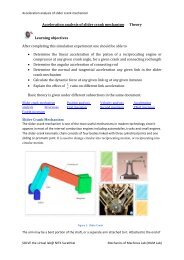
Position analysis of Grashoffour bar mechanism <strong>The</strong>ory<br />
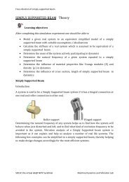
Learning objectives<br />
After completing this simulation experiment one should be able to<br />
<br />
<br />
<br />
<br />
Determine the location CG of any given link in a Grashof four bar<br />
mechanism<br />
Determine the output link angle of a Grashof four bar mechanism for any<br />
given crank angle<br />
Calculate the transmission angle of a given Grashof four bar mechanism at<br />
any given crank angle<br />
Synthesis length of a Grashof four bar mechanism for a given conditions<br />
Basic theory is given under different subsections in the same document.<br />
<strong>Introduction</strong><br />
<strong>Four</strong> <strong>Bar</strong> <strong>Mechanism</strong> Grashof Inversions Double crank mechanismCrankrocker<br />
mechanism Double-rocker mechanism Parallel crank<br />
mechanismPosition analysis, Velocity analysis Acceleration analysis<br />
<strong>Four</strong> <strong>Bar</strong> <strong>Mechanism</strong><br />
Figure 1: <strong>Four</strong> bar mechanism<br />
A four bar mechanism consists of four rigid link which are linked in the form of<br />
quadrilateral by four pin joints. A link that makes complete revolution is called crank, the link<br />
opposite to the fixed link is the coupler and forth link is a lever or rocker if oscillates or another<br />
crank if rotates. Here r 1, r 2, r 3 and r 4 are the links of the mechanisms.<br />
<strong>SOLVE</strong> the virtual lab@ <strong>NITK</strong> Surathkal<br />
Mechanics of Machines <strong>Lab</strong> (MoM <strong>Lab</strong>)
Position analysis of Grashoffour bar mechanism<br />
Figure 2: Nomenclature of four bar mechanism.<br />
Grashoff’s Law:<br />
For a planar four bar linkage, the sum of the shortest and longest links cannot be greater<br />
than the sum of the remaining links if there is to be continuous relative rotation between two<br />
members.<br />
Next<br />
<strong>SOLVE</strong> the virtual lab@ <strong>NITK</strong> Surathkal<br />
Mechanics of Machines <strong>Lab</strong> (MoM <strong>Lab</strong>)
Position analysis of Grashoffour bar mechanism<br />
Inversions<br />
Figure 3: Inversions of <strong>Four</strong> bar mechanism<br />
A mechanism has been defined above as a kinematic chain in which one of the links is fixed. From<br />
the four bar mechanism, different versions of each of them can be obtained by fixing any one of<br />
the links p, q l or s. Such different versions, which can be obtained by fixing any of the different<br />
links, are called its “Inversions”. Many a time, a particular inversion of a mechanism may give<br />
rise to different mechanisms of practical utility, when the proportions of the link lengths are<br />
changed.<br />
By this principle of inversion of a fourbar chain, several useful mechanisms can be obtained.<br />
<strong>The</strong>re are three inversions of four bar mechanisms, which are obtained by fixing different links of<br />
the kinematic chain. <strong>The</strong>y are:<br />
a) Double Crank <strong>Mechanism</strong><br />
b) Crank Rocker <strong>Mechanism</strong><br />
c) Double Rocker <strong>Mechanism</strong><br />
Previous<br />
Next<br />
<strong>SOLVE</strong> the virtual lab@ <strong>NITK</strong> Surathkal<br />
Mechanics of Machines <strong>Lab</strong> (MoM <strong>Lab</strong>)
Position analysis of Grashoffour bar mechanism<br />
Double Crank <strong>Mechanism</strong><br />
Figure 4: Double crank mechanism<br />
A double crank converts rotary motion from a crank to a second crank or link in a different<br />
plane or axis. It is also known as crank-crank, drag-crank or rotary-rotary converter. <strong>The</strong> links p,<br />
q and l shown above rotate through one complete revolution. This is one of the first inversions of<br />
four-bar mechanisms.<br />
In this discussion, let’s call the link‘s’ the frame as the fixed link. We will call the link ‘q’ the crank,<br />
‘p’ the coupler and ‘l’ the lever for now. Crank is not defined as the link, which is attached to the<br />
driver shaft; rather it’s the link, which does a complete revolution. And in this configuration, as<br />
there are two links, both q and l, which revolves completely about the hinged point on the frame,<br />
both of them, is cranks.<br />
<strong>The</strong> term is commonly used in automotive technology for the link in a four bar steering linkage<br />
that converts rotation of a steering arm to a center link and eventually to tie-rod links which<br />
pivot the wheels to be steered. A double crank is used when the steering arm operates in a plane<br />
above the other links. <strong>The</strong> double crank converts the sweeping arc of the steering arm to linear<br />
motion in the plane of the other steering links.<br />
Previous<br />
Next<br />
<strong>SOLVE</strong> the virtual lab@ <strong>NITK</strong> Surathkal<br />
Mechanics of Machines <strong>Lab</strong> (MoM <strong>Lab</strong>)
Position analysis of Grashoffour bar mechanism<br />
Crank-Rocker <strong>Mechanism</strong><br />
Figure 5: Crank lever mechanism<br />
In a four bar linkage, if the shorter side link revolves and the other rocks (i.e., oscillates), it is<br />
called a crank-rocker mechanism.<br />
In this case, there is only a slight change, leave the smallest side and connect any of its adjacent<br />
side as the frame. <strong>The</strong>n (in figure) the smallest side ‘s’ will have full 360 degree revolution while<br />
the other link adjacent to the frame has only oscillating motion (link p). This kind of mechanism<br />
is hence called a crank-lever mechanism or a crank-rocker mechanism or a rotary-oscillating<br />
converter.<br />
Previous<br />
Next<br />
<strong>SOLVE</strong> the virtual lab@ <strong>NITK</strong> Surathkal<br />
Mechanics of Machines <strong>Lab</strong> (MoM <strong>Lab</strong>)
Position analysis of Grashoffour bar mechanism<br />
Double-Rocker <strong>Mechanism</strong><br />
Figure 6: Double lever mechanism<br />
A linkage in which no link undergoes entire 360-degree revolution but only oscillations is known<br />
as a double-lever mechanism.<br />
This linkage results when the shortest side in the mechanism is made the coupler. <strong>The</strong> other two<br />
links only get to oscillate in their place. A linkage in which the sum of the longest and shortest<br />
link is less than the sum of the other two sides, is known as a Class I mechanism, otherwise it’s<br />
Class II. This mechanism is achieved when it is Class II. It’s also called rocker-rocker mechanism,<br />
double-rocker mechanism or oscillating oscillating-converter.<br />
Previous<br />
Next<br />
<strong>SOLVE</strong> the virtual lab@ <strong>NITK</strong> Surathkal<br />
Mechanics of Machines <strong>Lab</strong> (MoM <strong>Lab</strong>)
Position analysis of Grashoffour bar mechanism<br />
Parallel Crank <strong>Mechanism</strong><br />
Figure 7: Parallel crank mechanism<br />
If in a 4 bar linkage, two opposite links are parallel and equal in length, then any of the links can<br />
be made fixed, regardless, the two adjacent links will always act as a pair of cranks, i.e. , both will<br />
have complete revolution about their joints on the frame.<br />
<strong>The</strong> use of such mechanism is made in coupled wheels of locomotives in which the rotary motion<br />
of one wheel is transmitted to the other wheel.<br />
Previous<br />
<strong>SOLVE</strong> the virtual lab@ <strong>NITK</strong> Surathkal<br />
Mechanics of Machines <strong>Lab</strong> (MoM <strong>Lab</strong>)
Position analysis of Grashoffour bar mechanism<br />
Position analysis of four bar mechanism<br />
Figure 8: Configuration of four bar mechanism<br />
<strong>The</strong> position of the points on the links A (A x , A y ) and B (B x , B y )<br />
<strong>The</strong> coordinates of the point A are found using trigonometry as follows:<br />
Eq: 1<br />
Similarly coordinates of point B are found using the equations of circle around A and O 4 .<br />
Eq: 2<br />
Eq: 3<br />
Eq: 4<br />
where,<br />
<strong>The</strong> link angles are given by<br />
<strong>SOLVE</strong> the virtual lab@ <strong>NITK</strong> Surathkal<br />
Mechanics of Machines <strong>Lab</strong> (MoM <strong>Lab</strong>)
Position analysis of Grashoffour bar mechanism<br />
<strong>SOLVE</strong> the virtual lab@ <strong>NITK</strong> Surathkal<br />
Mechanics of Machines <strong>Lab</strong> (MoM <strong>Lab</strong>)