Download/Detectors/BGS-CM-TRNS IOM.pdf - Brasch
Download/Detectors/BGS-CM-TRNS IOM.pdf - Brasch
Download/Detectors/BGS-CM-TRNS IOM.pdf - Brasch

You also want an ePaper? Increase the reach of your titles
YUMPU automatically turns print PDFs into web optimized ePapers that Google loves.
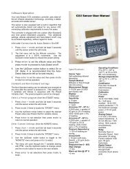
4.0 Specifications<br />
Proportional Outputs: 4 – 20 maDC 250Ω Maximum<br />
0 – 1 VDC 1000Ω Minimum<br />
0 – 5 VDC 1000Ω Minimum<br />
0 – 10 VDC 1000Ω Minimum<br />
Proportional outputs are field selectable.<br />
Calibration:<br />
The main transmitter module should be re-calibrated every three years.<br />
Contact the factory for re-calibration information and pricing.<br />
Ratings: Input Power: 24 VAC, 50/60 Hz, 28 VA<br />
Humidity: 10% to 90% (Non-Condensing)<br />
Temperature: Storage: -50 o C to 120 o C (-58 o F to 248 o F)<br />
Operating: -15 o C to 40 o C (5 o F to 104 o F)<br />
Installation Category:<br />
II (local level, over-voltage transients less than 500 volts)<br />
Indicators(LED Type): Green LED: Power ON<br />
Yellow LED: Sensor Failure<br />
Dimensions:<br />
Weight:<br />
7 5/8”H x 9 1/8”W x 2 1/4”D<br />
4 pounds<br />
Fuse Rating: Main Supply: 5x20MM, Time-Lag, 1.25 Amps<br />
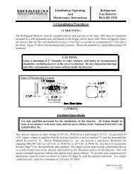
5.0 Troubleshooting<br />
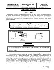
CAUTION:<br />
Only qualified personnel should attempt to service this equipment. All power<br />
sources must be disconnected before removing the cover of this transmitter.<br />
1. Power LED not on: A. Check for 20.4-26.4 VAC at terminals T1 & T2 (see Figure #2,<br />
Page 2).<br />
B. Check circuit board fuse for continuity. If the fuse needs to be<br />
replaced use only the rated fuse listed in the 4.0 Specifications<br />
Section.<br />
C. Consult the factory.<br />
2. Sensor failure light is on: A. Remove sensor and reinstall noting correct terminal markings.<br />
B. Replace transmitter board (includes sensor and calibration).<br />
C. Consult the factory.<br />
3. For any other situation please consult the factory.<br />
BULLETIN I-676<br />
3-2-99<br />
4