SECTION 15140 DOMESTIC WATER PIPING PART 1 - Balton ...
SECTION 15140 DOMESTIC WATER PIPING PART 1 - Balton ...
SECTION 15140 DOMESTIC WATER PIPING PART 1 - Balton ...

You also want an ePaper? Increase the reach of your titles
YUMPU automatically turns print PDFs into web optimized ePapers that Google loves.
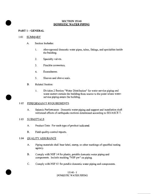
<strong>SECTION</strong> <strong>15140</strong><br />
<strong>DOMESTIC</strong> <strong>WATER</strong> <strong>PIPING</strong><br />
<strong>PART</strong> 1 - GENERAL<br />
1:01 SUMMARY<br />
A. Section Includes:<br />
1. Aboveground domestic water pipes, tubes, fittings, and specialties inside<br />
the building.<br />
2. Specialty valves.<br />
3. Flexible connectors.<br />
4. Escutcheons.<br />
5. Sleeves and sleeve seals.<br />
Related Section:<br />
1. Division 2 Section "Water Distribution" for water-service piping and<br />
water meters outside the building from source to the point where waterservice<br />
piping enters the building.<br />
1:02 PERFORMANCE REQUIREMENTS<br />
A. Seismic Performance: Domestic water piping and support and installation shall<br />
withstand effects of earthquake motions determined according to SE1/ASCE 7.<br />
1:03 SUBMITTALS<br />
A. Product Data: For each type of product indicated.<br />
B. Field quality-control reports.<br />
1:04 QUALITY ASSURANCE<br />
A. Piping materials shall bear label, stamp, or other markings of specified testing<br />
agency.<br />
B. Comply with NSF 14 for plastic, potable domestic water piping and<br />
components. Include marking "NSF-pw" on piping.<br />
C. Comply with NSF 61 for potable domestic water piping and components.<br />
<strong>15140</strong>-1<br />
<strong>DOMESTIC</strong> <strong>WATER</strong> <strong>PIPING</strong>
<strong>PART</strong> 2 - PRODUCTS<br />
2:01 <strong>PIPING</strong> MATERIALS<br />
A. Comply with requirements in "Piping Schedule" Article for applications of pipe,<br />
tube, fitting materials, and joining methods for specific services, service locations,<br />
and pipe sizes.<br />
2:02 COPPER TUBE AND FITTINGS<br />
A. Hard Copper Tube: ASTM B 88, Type L water tube, drawn temper.<br />
1. Cast-Copper Solder-Joint Fittings: ASME B16.18, pressure fittings.<br />
2. Wrought-Copper Solder-Joint Fittings: ASME B16.22, wrought-copper<br />
pressure fittings.<br />
3. Bronze Flanges: ASME B16.24, Class 150, with solder-joint ends.<br />
4. Copper Unions: MSS SP-123, cast-copper-alloy, hexagonal-stock body,<br />
with ball-and-socket, metal-to-metal seating surfaces, and solder-joint or<br />
threaded ends.<br />
5. Copper Pressure-Seal-Joint Fittings:<br />
a. Manufacturers: Subject to compliance with requirements, provide<br />
products by one of the following:<br />
1) Elkhart Products Corporation; Industrial Division.<br />
2) N1BCO INC.<br />
3) Viega; Plumbing and Heating Systems.<br />
b. NPS 2 and Smaller: Wrought-copper fitting with EPDM-rubber<br />
O-ring seal in each end.<br />
c. NPS 2-1/2 to NPS 4: Cast-bronze or wrought-copper fitting with<br />
EPDM-rubber O-ring seal in each end.<br />
B. Soft Copper Tube: ASTM B 88, Type K water tube, annealed temper.<br />
1. Copper Solder-Joint Fittings: ASME B16.22, wrought-copper pressure<br />
fittings.<br />
<strong>15140</strong>-2<br />
<strong>DOMESTIC</strong> <strong>WATER</strong> <strong>PIPING</strong>
2. Copper Pressure-Seal-Joint Fittings:<br />
a. Manufacturers: Subject to compliance with requirements, provide<br />
products by one of the following:<br />
1) Elkhart Products Corporation; Industrial Division.<br />
2) NIBCO INC.<br />
2:03 <strong>PIPING</strong> JOINING MATERIALS<br />
3) Viega; Plumbing and Heating Systems.<br />
b. NPS 2 and Smaller: Wrought-copper fitting with EPDM-rubber<br />
O-ring seal in each end.<br />
c. NPS 3 and NPS 4: Cast-bronze or wrought-copper fitting with<br />
EPDM-rubber O-ring seal in each end.<br />
A. Pipe-Flange Gasket Materials: AWWA CI 10, rubber, flat face, 1/8 inch thick or<br />
ASME Bl 6.21, nonmetallic and asbestos free, unless otherwise indicated; fullface<br />
or ring type unless otherwise indicated.<br />
B. Metal, Pipe-Flange Bolts and Nuts: ASME B 18.2.1, carbon steel unless<br />
otherwise indicated.<br />
C. Solder Filler Metals: ASTM B 32, lead-free alloys. Include water-flushable flux<br />
according to ASTM B 813.<br />
D. Brazing Filler Metals: AWS A5.8/A5.8M, BCuP Series, copper-phosphorus<br />
alloys for general-duty brazing unless otherwise indicated.<br />
E. Plastic, Pipe-Flange Gaskets, Bolts, and Nuts: Type and material recommended<br />
by piping system manufacturer unless otherwise indicated.<br />
2:04 SPECIALTY VALVES<br />
A. Comply with requirements in Division 15 Section "General-Duty Valves for<br />
Plumbing Piping" for general-duty metal valves.<br />
B. Comply with requirements in Division 15 Section "Domestic Water Piping<br />
Specialties" for balancing valves, drain valves, backflow preventers, and vacuum<br />
breakers.<br />
<strong>15140</strong>-3<br />
<strong>DOMESTIC</strong> <strong>WATER</strong> <strong>PIPING</strong>
2:05 TRANSITION FITTINGS<br />
A. Fitting-Type Transition Couplings: Manufactured piping coupling or specified<br />
piping system fitting.<br />
B. Sleeve-Type Transition Coupling: AWWA C219.<br />
2:06 DIELECTRIC FITTINGS<br />
A. General Requirements: Assembly of copper alloy and ferrous materials or ferrous<br />
material body with separating nonconductive insulating material suitable for<br />
system fluid, pressure, and temperature.<br />
B. Dielectric Unions:<br />
1. Description:<br />
C. Dielectric Flanges:<br />
a. Pressure Rating: 150 psig at 180 deg F.<br />
b. End Connections: Solder-joint copper alloy and threaded ferrous.<br />
1. Description:<br />
a. Factory-fabricated, bolted, companion-flange assembly.<br />
b. Pressure Rating: 150 psig minimum.<br />
c. End Connections: Solder-joint copper alloy and threaded ferrous;<br />
threaded solder-joint copper alloy and threaded ferrous.<br />
D. Dielectric-Flange Kits:<br />
1. Description:<br />
a. Non-conducting materials for field assembly of companion<br />
flanges.<br />
b. Pressure Rating: 150 psig.<br />
c. Gasket: Neoprene or phenolic.<br />
d. Bolt Sleeves: Phenolic or polyethylene.<br />
e. Washers: Phenolic with steel backing washers.<br />
<strong>15140</strong>-4<br />
<strong>DOMESTIC</strong> <strong>WATER</strong> <strong>PIPING</strong>
E. Dielectric Couplings:<br />
1. Description:<br />
F. Dielectric Nipples:<br />
a. Galvanized-steel coupling.<br />
b. Pressure Rating: 300 psig at 225 deg F.<br />
c. End Connections: Female threaded.<br />
d. Lining: Inert and noncorrosive, thermoplastic.<br />
1. Description:<br />
2:07 FLEXIBLE CONNECTORS<br />
a. Electroplated steel nipple complying with ASTM F 1545.<br />
b. Pressure Rating: 300 psig at 225 deg F.<br />
c. End Connections: Male threaded or grooved.<br />
d. Lining: Inert and noncorrosive, propylene.<br />
A. Bronze-Hose Flexible Connectors: Corrugated-bronze tubing with bronze wirebraid<br />
covering and ends brazed to inner tubing.<br />
1. Working-Pressure Rating: Minimum 200 psig<br />
2. End Connections NPS 2 and Smaller: Threaded copper pipe or plain-end<br />
copper tube.<br />
3. End Connections NPS 2-1/2 and Larger: Flanged copper alloy.<br />
B. Stainless-Steel-Hose Flexible Connectors: Corrugated-stainless-steel tubing with<br />
stainless-steel wire-braid covering and ends welded to inner tubing.<br />
1. Working-Pressure Rating: Minimum 200 psig.<br />
2. End Connections NPS 2 and Smaller: Threaded steel-pipe nipple.<br />
3. End Connections NPS 2-1/2 and Larger: Flanged steel nipple.<br />
<strong>15140</strong>-5<br />
<strong>DOMESTIC</strong> <strong>WATER</strong> <strong>PIPING</strong>
2:08 ESCUTCHEONS<br />
A. General: Manufactured ceiling, floor, and wall escutcheons and floor plates.<br />
B. One Piece, Cast Brass: Polished, chrome-plated or rough-brass finish with<br />
setscrews.<br />
C. One Piece, Deep Pattern: Deep-drawn, box-shaped brass with chrome-plated<br />
finish.<br />
D. One Piece, Stamped Steel: Chrome-plated finish with setscrew or spring clips.<br />
E. Split Casting, Cast Brass: Polished, chrome-plated or rough-brass finish with<br />
concealed hinge and setscrew.<br />
F. Split Plate, Stamped Steel: Chrome-plated finish with concealed hinge, setscrew<br />
or spring clips.<br />
G. One-Piece Floor Plates: Cast-iron flange with holes for fasteners.<br />
H. Split-Casting Floor Plates: Cast brass with concealed hinge.<br />
2:09 SLEEVES<br />
A. Cast-Iron Wall Pipes: Fabricated of cast iron, and equivalent to ductile-iron<br />
pressure pipe, with plain ends and integral waterstop unless otherwise indicated.<br />
B. Galvanized-Steel-Sheet Sleeves: 0.0239-inch minimum thickness; round tube<br />
closed with welded longitudinal joint.<br />
C. PVC-Pipe Sleeves: ASTM D 1785, Schedule 40.<br />
D. Galvanized-Steel-Pipe Sleeves: ASTM A 53/A 53M, Type E, Grade B,<br />
Schedule 40, zinc-coated, with plain ends.<br />
E. Stack Sleeve Fittings: Manufactured, cast-iron sleeve with integral clamping<br />
flange. Include clamping ring and bolts and nuts for membrane flashing.<br />
2:10 SLEEVE SEALS<br />
1. Underdeck Clamp: Clamping ring with setscrews.<br />
A. Description: Modular sealing element unit, designed for field assembly, used to<br />
fill annular space between pipe and sleeve.<br />
<strong>15140</strong>-6<br />
<strong>DOMESTIC</strong> <strong>WATER</strong> <strong>PIPING</strong>
2:11 GROUT<br />
1. Sealing Elements: EPDM-rubber interlocking links shaped to fit surface<br />
of pipe. Include type and number required for pipe material and size of<br />
pipe.<br />
2. Pressure Plates: Stainless steel.<br />
3. Connecting Bolts and Nuts: Stainless steel of length required to secure<br />
pressure plates to sealing elements.<br />
A. Standard: ASTM C 1107, Grade B, post-hardening and volume-adjusting, dry,<br />
hydraulic-cement grout.<br />
B. Characteristics: Nonshrink; recommended for interior and exterior applications.<br />
C. Design Mix: 5000-psi, 28-day compressive strength.<br />
D. Packaging: Premixed and factory packaged.<br />
<strong>PART</strong> 3 - EXECUTION<br />
3:01 <strong>PIPING</strong> INSTALLATION<br />
A. Drawing plans, schematics, and diagrams indicate general location and<br />
arrangement of domestic water piping. Indicated locations and arrangements are<br />
used to size pipe and calculate friction loss, expansion, and other design<br />
considerations. Install piping as indicated unless deviations to layout are<br />
approved on Coordination Drawings.<br />
B. Install copper tubing under building slab according to CDA's "Copper Tube<br />
Handbook."<br />
C. Install shutoff valve, hose-end drain valve, strainer, pressure gage, and test tee<br />
with valve, inside the building at each domestic water service entrance. Comply<br />
with requirements in Division 15 Section "Meters and Gages for Plumbing<br />
Piping" for pressure gages and Division 15 Section "Domestic Water Piping<br />
Specialties" for drain valves and strainers.<br />
D. Install shutoff valve immediately upstream of each dielectric fitting.<br />
E. Install domestic water piping level without slope and plumb.<br />
F. Rough-in domestic water piping for water-meter installation according to utility<br />
company's requirements.<br />
<strong>15140</strong>-7<br />
<strong>DOMESTIC</strong> <strong>WATER</strong> <strong>PIPING</strong>
G. Install seismic restraints on piping. Comply with requirements in Division 15<br />
Section "Vibration and Seismic Controls for Plumbing Piping and Equipment" for<br />
seismic-restraint devices.<br />
H. Install piping concealed from view and protected from physical contact by<br />
building occupants unless otherwise indicated and except in equipment rooms and<br />
service areas.<br />
I. Install piping indicated to be exposed and piping in equipment rooms and service<br />
areas at right angles or parallel to building walls. Diagonal runs are prohibited<br />
unless specifically indicated otherwise.<br />
J. Install piping above accessible ceilings to allow sufficient space for ceiling panel<br />
removal, and coordinate with other services occupying that space.<br />
K. Install piping adjacent to equipment and specialties to allow service and<br />
maintenance.<br />
L. Install piping to permit valve servicing.<br />
M. Install nipples, unions, special fittings, and valves with pressure ratings the same<br />
as or higher than system pressure rating used in applications below unless<br />
otherwise indicated.<br />
N. Install piping free of sags and bends.<br />
O. Install fittings for changes in direction and branch connections.<br />
P. Install unions in copper tubing at final connection to each piece of equipment,<br />
machine, and specialty.<br />
Q. Install pressure gages on suction and discharge piping from each plumbing pump<br />
and packaged booster pump. Comply with requirements in Division 15 Section<br />
"Meters and Gages for Plumbing Piping" for pressure gages.<br />
R. Install thermostats in hot-water circulation piping. Comply with requirements in<br />
Division 15 Section "Domestic Water Pumps" for thermostats.<br />
S. Install thermometers on outlet piping from each water heater. Comply with<br />
requirements in Division 15 Section "Meters and Gages for Plumbing Piping" for<br />
thermometers.<br />
3:02 JOINT CONSTRUCTION<br />
A. Ream ends of pipes and tubes and remove burrs. Bevel plain ends of steel pipe.<br />
I5I40-8<br />
<strong>DOMESTIC</strong> <strong>WATER</strong> <strong>PIPING</strong>
B. Remove scale, slag, dirt, and debris from inside and outside of pipes, tubes, and<br />
fittings before assembly.<br />
C. Threaded Joints: Thread pipe with tapered pipe threads according to<br />
ASME B 1.20.1. Cut threads full and clean using sharp dies. Ream threaded pipe<br />
ends to remove burrs and restore full ID. Join pipe fittings and valves as follows:<br />
1. Apply appropriate tape or thread compound to external pipe threads.<br />
2. Damaged Threads: Do not use pipe or pipe fittings with threads that are<br />
corroded or damaged.<br />
D. Brazed Joints: Join copper tube and fittings according to CDA's "Copper Tube<br />
Handbook," "Brazed Joints" Chapter.<br />
E. Soldered Joints: Apply ASTM B 813, water-flu shable flux to end of tube. Join<br />
copper tube and fittings according to ASTM B 828 or CDA's "Copper Tube<br />
Handbook."<br />
F. Pressure-Sealed Joints: Join copper tube and pressure-seal fittings with tools<br />
recommended by fitting manufacturer.<br />
G. Flanged Joints: Select appropriate asbestos-free, nonmetallic gasket material in<br />
size, type, and thickness suitable for domestic water service. Join flanges with<br />
gasket and bolts according to ASME B31.9.<br />
H. Dissimilar-Material Piping Joints: Make joints using adapters compatible with<br />
materials of both piping systems.<br />
3:03 VALVE INSTALLATION<br />
A. General-Duty Valves: Comply with requirements in Division 15 Section<br />
"General-Duty Valves for Plumbing Piping" for valve installations.<br />
B. Install shutoff valve close to water main on each branch and riser serving<br />
plumbing fixtures or equipment, on each water supply to equipment, and on each<br />
water supply to plumbing fixtures that do not have supply stops. Use ball or gate<br />
valves for piping NPS 2 and smaller. Use butterfly or gate valves for piping<br />
NPS 2-1/2 and larger.<br />
C. Install drain valves for equipment at base of each water riser, at low points in<br />
horizontal piping, and where required to drain water piping. Drain valves are<br />
specified in Division 15 Section "Domestic Water Piping Specialties."<br />
1. Hose-End Drain Valves: At low points in water mains, risers, and<br />
branches.<br />
<strong>15140</strong>-9<br />
<strong>DOMESTIC</strong> <strong>WATER</strong> <strong>PIPING</strong>
2. Stop-and-Waste Drain Valves: Instead of hose-end drain valves where<br />
indicated.<br />
D. Install balancing valve in each hot-water circulation return branch and discharge<br />
side of each pump and circulator. Set balancing valves partly open to restrict but<br />
not stop flow. Use ball valves for piping NPS 2 and smaller and butterfly valves<br />
for piping NPS 2-1/2 and larger. Comply with requirements in Division 15<br />
Section "Domestic Water Piping Specialties" for balancing valves.<br />
3:04 TRANSITION FITTING INSTALLATION<br />
A. Install transition couplings at joints of dissimilar piping.<br />
B. Transition Fittings in Aboveground Domestic Water Piping NPS 2 and Smaller:<br />
Plastic-to-metal transition fittings or unions.<br />
3:05 DIELECTRIC FITTING INSTALLATION<br />
A. Install dielectric fittings in piping at connections of dissimilar metal piping and<br />
tubing.<br />
B. Dielectric Fittings for NPS 2 and Smaller: Use dielectric couplings or nipples.<br />
C. Dielectric Fittings for NPS 2-1/2 to NPS 4: Use dielectric flange kits.<br />
D. Dielectric Fittings for NPS 5 to NPS 6: Use dielectric flange kits.<br />
3:06 HANGER AND SUPPORT INSTALLATION<br />
A. Comply with requirements in Division 15 Section "Vibration and Seismic<br />
Controls for Plumbing Piping and Equipment" for seismic-restraint devices.<br />
B. Comply with requirements in Division 15 Section "Hangers and Supports for<br />
Plumbing Piping and Equipment" for pipe hanger and support products and<br />
installation.<br />
1. Vertical Piping: MSS Type 8 or 42, clamps.<br />
2. Individual, Straight, Horizontal Piping Runs:<br />
a. 100 Feet and Less: MSS Type 1, adjustable, steel clevis hangers.<br />
b. Longer Than 100 Feet: MSS Type 43, adjustable roller hangers.<br />
3. Base of Vertical Piping: MSS Type 52, spring hangers.<br />
<strong>15140</strong>-10<br />
<strong>DOMESTIC</strong> <strong>WATER</strong> <strong>PIPING</strong>
C. Support vertical piping and tubing at base and at each floor.<br />
D. Support piping and tubing not listed in this article according to MSS SP-69 and<br />
manufacturer's written instructions.<br />
3:07 CONNECTIONS<br />
A. Drawings indicate general arrangement of piping, fittings, and specialties.<br />
B. Install piping adjacent to equipment and machines to allow service and<br />
maintenance.<br />
C. Connect domestic water piping to exterior water-service piping. Use transition<br />
fitting to join dissimilar piping materials.<br />
D. Connect domestic water piping to water-service piping with shutoff valve; extend<br />
and connect to the following:<br />
1. Water Heaters: Cold-water inlet and hot-water outlet piping in sizes<br />
indicated, but not smaller than sizes of water heater connections.<br />
2. Plumbing Fixtures: Cold- and hot-water supply piping in sizes indicated,<br />
but not smaller than required by plumbing code. Comply with<br />
requirements in Division 15 plumbing fixture Sections for connection<br />
sizes.<br />
3. Equipment: Cold- and hot-water supply piping as indicated, but not<br />
smaller than equipment connections. Provide shutoff valve and union for<br />
each connection. Use flanges instead of unions for NPS 2-1/2 and larger.<br />
3:08 ESCUTCHEON INSTALLATION<br />
A. Install escutcheons for penetrations of walls, ceilings, and floors.<br />
B. Escutcheons for New Piping:<br />
1. Piping with Fitting or Sleeve Protruding from Wall: One piece, deep<br />
pattern.<br />
2. Bare Piping at Wall and Floor Penetrations in Finished Spaces: One<br />
piece, cast brass with polished chrome-plated finish.<br />
3. Bare Piping at Ceiling Penetrations in Finished Spaces: One piece, cast<br />
brass with polished chrome-plated finish.<br />
<strong>15140</strong>-11<br />
<strong>DOMESTIC</strong> <strong>WATER</strong> <strong>PIPING</strong>
4. Bare Piping in Unfinished Service Spaces: One piece, cast brass with<br />
polished chrome-plated finish.<br />
5. Bare Piping in Equipment Rooms: One piece, cast brass.<br />
6. Bare Piping at Floor Penetrations in Equipment Rooms: One-piece floor<br />
plate.<br />
3:09 SLEEVE INSTALLATION<br />
A. General Requirements: Install sleeves for pipes and tubes passing through<br />
penetrations in floors, partitions, roofs, and walls.<br />
B. Sleeves are not required for core-drilled holes.<br />
C. Permanent sleeves are not required for holes formed by removable PE sleeves.<br />
D. Cut sleeves to length for mounting flush with both surfaces unless otherwise<br />
indicated.<br />
E. Install sleeves in new partitions, slabs, and walls as they are built.<br />
F. For interior wall penetrations, seal annular space between sleeve and pipe or pipe<br />
insulation using joint sealants appropriate for size, depth, and location of joint.<br />
Comply with requirements in Division 7 Section "Joint Sealants" for joint<br />
sealants.<br />
G. For exterior wall penetrations above grade, seal annular space between sleeve and<br />
pipe using joint sealants appropriate for size, depth, and location of joint. Comply<br />
with requirements in Division 7 Section "Joint Sealants" for joint sealants.<br />
H. For exterior wall penetrations below grade, seal annular space between sleeve and<br />
pipe using sleeve seals specified in this Section.<br />
I. Seal space outside of sleeves in concrete slabs and walls with grout.<br />
J. Install sleeves that are large enough to provide 1/4-inch annular clear space<br />
between sleeve and pipe or pipe insulation unless otherwise indicated.<br />
K. Install sleeve materials according to the following applications:<br />
1. Sleeves for Piping Passing through Concrete Floor Slabs: Steel pipe.<br />
2. Sleeves for Piping Passing through Concrete Floor Slabs of Mechanical<br />
Equipment Areas or Other Wet Areas: Stack sleeve fittings.<br />
<strong>15140</strong>-12<br />
<strong>DOMESTIC</strong> <strong>WATER</strong> <strong>PIPING</strong>
a. Extend sleeves 2 inches above finished floor level.<br />
b. For pipes penetrating floors with membrane waterproofing, extend<br />
cast-iron sleeve fittings below floor slab as required to secure<br />
clamping ring if ring is specified. Secure flashing between<br />
clamping flanges. Install section of cast-iron soil pipe to extend<br />
sleeve to 2 inches above finished floor level. Comply with<br />
requirements in Division 7 Section "Sheet Metal Flashing and<br />
Trim" for flashing.<br />
3. Sleeves for Piping Passing through Gypsum-Board Partitions:<br />
a. PVC pipe sleeves for pipes smaller than NPS 6.<br />
b. Galvanized-steel sheet sleeves for pipes NPS 6 and larger.<br />
c. Exception: Sleeves are not required for water supply tubes and<br />
waste pipes for individual plumbing fixtures if escutcheons will<br />
cover openings.<br />
4. Sleeves for Piping Passing through Concrete Roof Slabs: Steel pipe.<br />
5. Sleeves for Piping Passing through Exterior Concrete Walls:<br />
a. Steel pipe sleeves for pipes smaller than NPS 6.<br />
b. Cast-iron wall pipe sleeves for pipes NPS 6 and larger.<br />
c. Install sleeves that are large enough to provide 1-inch annular clear<br />
space between sleeve and pipe or pipe insulation when sleeve seals<br />
are used.<br />
L. Fire-Barrier Penetrations: Maintain indicated fire rating of walls, partitions,<br />
ceilings, and floors at pipe penetrations. Seal pipe penetrations with fire stop<br />
materials. Comply with requirements in Division 7 Section "Through-Penetration<br />
Fire stop Systems" for fire stop materials and installations.<br />
3:10 SLEEVE SEAL INSTALLATION<br />
A. Install sleeve seals in sleeves in exterior concrete walls at water-service piping<br />
entries into building.<br />
B. Select type and number of sealing elements required for pipe material and size.<br />
Position pipe in center of sleeve. Assemble sleeve seal components and install in<br />
annular space between pipe and sleeve. Tighten bolts against pressure plates that<br />
cause sealing elements to expand and make watertight seal.<br />
<strong>15140</strong>-13<br />
<strong>DOMESTIC</strong> <strong>WATER</strong> <strong>PIPING</strong>
3:11 IDENTIFICATION<br />
A. Identify system components. Comply with requirements in Division 15 Section<br />
"Identification for Plumbing Piping and Equipment" for identification materials<br />
and installation.<br />
B. Label pressure piping with system operating pressure.<br />
3:12 FIELD QUALITY CONTROL<br />
A. Perform tests and inspections.<br />
B. Piping Inspections:<br />
1. Do not enclose, cover, or put piping into operation until it has been<br />
inspected and approved by authorities having jurisdiction.<br />
2. During installation, notify authorities having jurisdiction at least one day<br />
before inspection must be made. Perform tests specified below in<br />
presence of authorities havingjurisdiction:<br />
a. Roughing-in Inspection: Arrange for inspection of piping before<br />
concealing or closing-in after roughing-in and before setting<br />
fixtures.<br />
b. Final Inspection: Arrange final inspection for authorities having<br />
jurisdiction to observe tests specified below and to ensure<br />
compliance with requirements.<br />
3.<br />
4.<br />
Re-inspection: If authorities havingjurisdiction find that piping will not<br />
pass tests or inspections, make required corrections and arrange for reinspection.<br />
Reports: Prepare inspection reports and have them signed by authorities<br />
having jurisdiction.<br />
C. Piping Tests:<br />
1.<br />
2.<br />
Fill domestic water piping. Check components to determine that they are<br />
not air bound and that piping is full of water.<br />
Test for leaks and defects in new piping and parts of existing piping that<br />
have been altered, extended, or repaired. If testing is performed in<br />
segments, submit a separate report for each test, complete with diagram of<br />
portion of piping tested.<br />
<strong>15140</strong>-14<br />
<strong>DOMESTIC</strong> <strong>WATER</strong> <strong>PIPING</strong>
3. Leave new, altered, extended, or replaced domestic water piping<br />
uncovered and unconcealed until it has been tested and approved. Expose<br />
work that was covered or concealed before it was tested.<br />
4. Cap and subject piping to static water pressure of 50 psig above operating<br />
pressure, without exceeding pressure rating of piping system materials.<br />
Isolate test source and allow to stand for four hours. Leaks and loss in test<br />
pressure constitute defects that must be repaired.<br />
5. Repair leaks and defects with new materials and retest piping or portion<br />
thereof until satisfactory results are obtained.<br />
6. Prepare reports for tests and for corrective action required.<br />
D. Domestic water piping will be considered defective if it does not pass tests and<br />
inspections.<br />
E. Prepare test and inspection reports.<br />
3:13 CLEANING<br />
A. Clean and disinfect potable domestic water piping as follows:<br />
1. Purge new piping and parts of existing piping that have been altered,<br />
extended, or repaired before using.<br />
2. Use purging and disinfecting procedures prescribed by authorities having<br />
jurisdiction; if methods are not prescribed, use procedures described in<br />
either AWWA C651 or AWWA C652 or follow procedures described<br />
below:<br />
a. Flush piping system with clean, potable water until dirty water<br />
does not appear at outlets.<br />
b. Fill and isolate system according to either of the following:<br />
1) Fill system or part thereof with water/chlorine solution with<br />
at least 50 ppm of chlorine. Isolate with valves and allow<br />
to stand for 24 hours.<br />
2) Fill system or part thereof with water/chlorine solution with<br />
at least 200 ppm of chlorine. Isolate and allow to stand for<br />
three hours.<br />
c. Flush system with clean, potable water until no chlorine is in water<br />
coming from system after the standing time.<br />
<strong>15140</strong>-15<br />
<strong>DOMESTIC</strong> <strong>WATER</strong> <strong>PIPING</strong>
d. Submit water samples in sterile bottles to authorities having<br />
jurisdiction. Repeat procedures if biological examination shows<br />
contamination.<br />
B. Prepare and submit reports of purging and disinfecting activities.<br />
C. Clean interior of domestic water piping system. Remove dirt and debris as work<br />
progresses.<br />
3:14 <strong>PIPING</strong> SCHEDULE<br />
A. Transition and special fittings with pressure ratings at least equal to piping rating<br />
may be used in applications below unless otherwise indicated.<br />
B. Flanges and unions may be used for aboveground piping joints unless otherwise<br />
indicated.<br />
C. Under-building-slab, domestic water, building service piping, NPS 3 and smaller,<br />
shall be the following:<br />
1. Soft copper tube, ASTM B 88, Type K; wrought-copper solder-joint<br />
fittings; and brazed joints.<br />
D. Aboveground domestic water piping, NPS 2 and smaller, shall be the following:<br />
1. Hard copper tube, ASTM B 88, Type L; wrought-copper solder-joint<br />
fittings; and soldered joints.<br />
E. Aboveground domestic water piping, NPS 2-1/2 to NPS 4, shall be the following:<br />
3:15 VALVE SCHEDULE<br />
1. Hard copper tube, ASTM B 88, Type L; wrought-copper solder-joint<br />
fittings; and soldered joints.<br />
A. Drawings indicate valve types to be used. Where specific valve types are not<br />
indicated, the following requirements apply:<br />
1. Shutoff Duty: Use ball or gate valves for piping NPS 2 and smaller. Use<br />
butterfly, ball, or gate valves with flanged ends for piping NPS 2-1/2 and<br />
larger.<br />
2. Throttling Duty: Use ball or globe valves for piping NPS 2 and smaller.<br />
Use butterfly or ball valves with flanged ends for piping NPS 2-1/2 and<br />
larger.<br />
<strong>15140</strong>-16<br />
<strong>DOMESTIC</strong> <strong>WATER</strong> <strong>PIPING</strong>
3. Hot-Water Circulation Piping, Balancing Duty: Memory-stop balancing<br />
valves.<br />
4. Drain Duty: Hose-end drain valves.<br />
Use check valves to maintain correct direction of domestic water flow to and from<br />
equipment.<br />
END OF <strong>SECTION</strong><br />
<strong>15140</strong>-17<br />
<strong>DOMESTIC</strong> <strong>WATER</strong> <strong>PIPING</strong>