The Pantograph Mk-II: A Haptic Instrument - CIM - McGill University
The Pantograph Mk-II: A Haptic Instrument - CIM - McGill University
The Pantograph Mk-II: A Haptic Instrument - CIM - McGill University

You also want an ePaper? Increase the reach of your titles
YUMPU automatically turns print PDFs into web optimized ePapers that Google loves.
<strong>II</strong>. COMPONENTS<br />
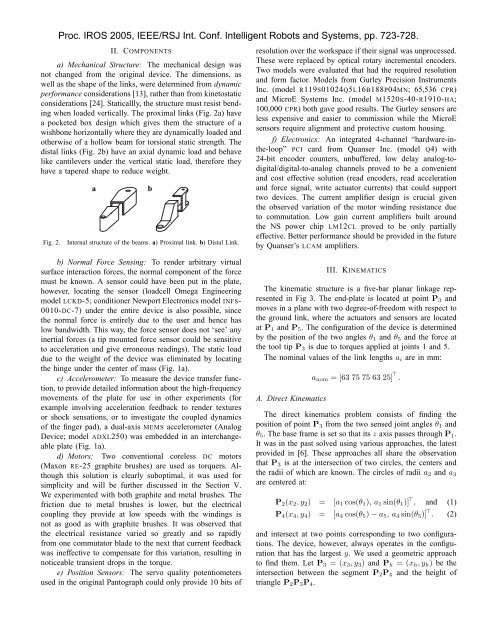
a) Mechanical Structure: <strong>The</strong> mechanical design was<br />
not changed from the original device. <strong>The</strong> dimensions, as<br />
well as the shape of the links, were determined from dynamic<br />
performance considerations [13], rather than from kinetostatic<br />
considerations [24]. Staticallly, the structure must resist bending<br />
when loaded vertically. <strong>The</strong> proximal links (Fig. 2a) have<br />
a pocketed box design which gives them the structure of a<br />
wishbone horizontally where they are dynamically loaded and<br />
otherwise of a hollow beam for torsional static strength. <strong>The</strong><br />
distal links (Fig. 2b) have an axial dynamic load and behave<br />
like cantilevers under the vertical static load, therefore they<br />
have a tapered shape to reduce weight.<br />
Fig. 2.<br />
Proc. IROS 2005, IEEE/RSJ Int. Conf. Intelligent Robots and Systems, pp. 723-728.<br />
a<br />
b<br />
Internal structure of the beams. a) Proximal link. b) Distal Link.<br />
resolution over the workspace if their signal was unprocessed.<br />
<strong>The</strong>se were replaced by optical rotary incremental encoders.<br />
Two models were evaluated that had the required resolution<br />
and form factor. Models from Gurley Precision <strong>Instrument</strong>s<br />
Inc. (model R119S01024Q5L16B188P04MN; 65,536 CPR)<br />
and MicroE Systems Inc. (model M1520S-40-R1910-HA;<br />
100,000 CPR) both gave good results. <strong>The</strong> Gurley sensors are<br />
less expensive and easier to commission while the MicroE<br />
sensors require alignment and protective custom housing.<br />
f) Electronics: An integrated 4-channel “hardware-inthe-loop”<br />
PCI card from Quanser Inc. (model Q4) with<br />
24-bit encoder counters, unbuffered, low delay analog-todigital/digital-to-analog<br />
channels proved to be a convenient<br />
and cost effective solution (read encoders, read acceleration<br />
and force signal, write actuator currents) that could support<br />
two devices. <strong>The</strong> current amplifier design is crucial given<br />
the observed variation of the motor winding resistance due<br />
to commutation. Low gain current amplifiers built around<br />
the NS power chip LM12CL proved to be only partially<br />
effective. Better performance should be provided in the future<br />
by Quanser’s LCAM amplifiers.<br />
b) Normal Force Sensing: To render arbitrary virtual<br />
surface interaction forces, the normal component of the force<br />
must be known. A sensor could have been put in the plate,<br />
however, locating the sensor (loadcell Omega Engineering<br />
model LCKD-5; conditioner Newport Electronics model INFS-<br />
0010-DC-7) under the entire device is also possible, since<br />
the normal force is entirely due to the user and hence has<br />
low bandwidth. This way, the force sensor does not ‘see’ any<br />
inertial forces (a tip mounted force sensor could be sensitive<br />
to acceleration and give erroneous readings). <strong>The</strong> static load<br />
due to the weight of the device was eliminated by locating<br />
the hinge under the center of mass (Fig. 1a).<br />
c) Accelerometer: To measure the device transfer function,<br />
to provide detailed information about the high-frequency<br />
movements of the plate for use in other experiments (for<br />
example involving acceleration feedback to render textures<br />
or shock sensations, or to investigate the coupled dynamics<br />
of the finger pad), a dual-axis MEMS accelerometer (Analog<br />
Device; model ADXL250) was embedded in an interchangeable<br />
plate (Fig. 1a).<br />
d) Motors: Two conventional coreless DC motors<br />
(Maxon RE-25 graphite brushes) are used as torquers. Although<br />
this solution is clearly suboptimal, it was used for<br />
simplicity and will be further discussed in the Section V.<br />
We experimented with both graphite and metal brushes. <strong>The</strong><br />
friction due to metal brushes is lower, but the electrical<br />
coupling they provide at low speeds with the windings is<br />
not as good as with graphite brushes. It was observed that<br />
the electrical resistance varied so greatly and so rapidly<br />
from one commutator blade to the next that current feedback<br />
was ineffective to compensate for this variation, resulting in<br />
noticeable transient drops in the torque.<br />
e) Position Sensors: <strong>The</strong> servo quality potentiometers<br />
used in the original <strong>Pantograph</strong> could only provide 10 bits of<br />
<strong>II</strong>I. KINEMATICS<br />
<strong>The</strong> kinematic structure is a five-bar planar linkage represented<br />
in Fig 3. <strong>The</strong> end-plate is located at point P 3 and<br />
moves in a plane with two degree-of-freedom with respect to<br />
the ground link, where the actuators and sensors are located<br />
at P 1 and P 5 . <strong>The</strong> configuration of the device is determined<br />
by the position of the two angles θ 1 and θ 5 and the force at<br />
the tool tip P 3 is due to torques applied at joints 1 and 5.<br />
<strong>The</strong> nominal values of the link lengths a i are in mm:<br />
A. Direct Kinematics<br />
a nom = [63 75 75 63 25] ⊤ .<br />
<strong>The</strong> direct kinematics problem consists of finding the<br />
position of point P 3 from the two sensed joint angles θ 1 and<br />
θ 5 . <strong>The</strong> base frame is set so that its z axis passes through P 1 .<br />
It was in the past solved using various approaches, the latest<br />
provided in [6]. <strong>The</strong>se approaches all share the observation<br />
that P 3 is at the intersection of two circles, the centers and<br />
the radii of which are known. <strong>The</strong> circles of radii a 2 and a 3<br />
are centered at:<br />
P 2 (x 2 , y 2 ) = [a 1 cos(θ 1 ), a 1 sin(θ 1 )] ⊤ , and (1)<br />
P 4 (x 4 , y 4 ) = [a 4 cos(θ 5 ) − a 5 , a 4 sin(θ 5 )] ⊤ . (2)<br />
and intersect at two points corresponding to two configurations.<br />
<strong>The</strong> device, however, always operates in the configuration<br />
that has the largest y. We used a geometric approach<br />
to find them. Let P 3 = (x 3 , y 3 ) and P h = (x h , y h ) be the<br />
intersection between the segment P 2 P 4 and the height of<br />
triangle P 2 P 3 P 4 .