The Pantograph Mk-II: A Haptic Instrument - CIM - McGill University
The Pantograph Mk-II: A Haptic Instrument - CIM - McGill University The Pantograph Mk-II: A Haptic Instrument - CIM - McGill University
Proc. IROS 2005, IEEE/RSJ Int. Conf. Intelligent Robots and Systems, pp. 723-728. The Pantograph Mk-II: A Haptic Instrument ∗ Gianni Campion, Student Member, IEEE, Qi Wang, Member, IEEE, and Vincent Hayward, Senior Member, IEEE Haptics Laboratory Centre for Intelligent Machines McGill University 3480 University Street, H3A 2A7, Montréal, Québec, Canada www.cim.mcgill.ca/∼haptic Abstract— We describe the redesign and the performance evaluation of a high-performance haptic device system called the Pantograph. The device is based on a two degree-of-freedom parallel mechanism which was designed for optimized dynamic performance, but which also is well kinematically conditioned. The results show that the system is capable of producing accurate tactile signals in the DC–400 Hz range and can resolve displacements of the order of 10 µm. Future improvements are discussed. Index Terms— Haptic Devices. Parallel Mechanimsms. Mechanism Conditioning. Performance Measures. could be used as a scientific instrument. Our intention is to make the system available in open-source, hardware and software. An important aspect of the Pantograph, a planar parallel mechanism (Fig. 1d), is the nature of its interface: a nonslip plate on which the fingerpad rests (Fig. 1e). Judiciously programmed tangential interaction forces f T at the interface (Fig. 1e) have the effect of causing fingertip deformations and tactile sensations that resemble exploring real surfaces. I. INTRODUCTION The scientific study of touch, the design of computational methods to synthesize tactile signals, studies in the control of haptic interfaces, the development of force reflecting virtual environments, and other activities, all require the availability of devices that can produce reliable haptic interaction signals. In some cases, it is needed to produce well controlled stimuli. In other cases, it is important to have the knowledge of the structural dynamics of a device, but in all cases, these activities entail having devices which are well characterized. Following SensAble’s Phantom R○ and Immersion’s Impulse Engine R○, several new commercially-available generalpurpose haptic devices have been recently introduced: MPB’s Freedom-6S R○, Force Dimension’s Omega R○, Haption’s Virtuose R○, Immersion Canada’s PenCat/Pro R○; plus other application-specific devices. In addition, interesting, low-complexity, high-performance devices have also become available, either from research institutions or from commercial sources [9], [10], [15], [21]. We felt, nonetheless, that a general-purpose laboratory system having high performance features, would be a valuable tool. With this in mind, we set out to redesign the ‘Pantograph’ haptic device, first demonstrated at the 1994 ACM SIGCHI conference in Boston, MA [22]. Our first goal was the creation of an open architecture system which could be easily replicated from blueprints and from a list of off-the-shelf components. The second goal was to obtain a system which would have superior and known performance characteristics so that it ∗ This research was supported in part by the Institute for Robotics and Intelligent Systems, and in part by the Natural Sciences and Engineering Research Council of Canada. c a Encoders Torquers Interface Plate Accelerometer (optional) Load Cell e f T f N b d 104 mm 66 mm Fig. 1. Pantograph Mk II electromechanical hardware. a) Side view showing the main electromechanical components. b) Front view. c) Photograph. d) Top view of the five-bar mechanism and plate constrained to 2-DOF. e) The interaction force has two components: f N is measured by the load cell and f T results from coupling the finger tip to the actuators via linkages.
- Page 2 and 3: II. COMPONENTS a) Mechanical Struct
- Page 4 and 5: Proc. IROS 2005, IEEE/RSJ Int. Conf
- Page 6: Proc. IROS 2005, IEEE/RSJ Int. Conf
Proc. IROS 2005, IEEE/RSJ Int. Conf. Intelligent Robots and Systems, pp. 723-728.<br />
<strong>The</strong> <strong>Pantograph</strong> <strong>Mk</strong>-<strong>II</strong>: A <strong>Haptic</strong> <strong>Instrument</strong> ∗<br />
Gianni Campion, Student Member, IEEE, Qi Wang, Member, IEEE,<br />
and Vincent Hayward, Senior Member, IEEE<br />
<strong>Haptic</strong>s Laboratory<br />
Centre for Intelligent Machines<br />
<strong>McGill</strong> <strong>University</strong><br />
3480 <strong>University</strong> Street, H3A 2A7, Montréal, Québec, Canada<br />
www.cim.mcgill.ca/∼haptic<br />
Abstract— We describe the redesign and the performance<br />
evaluation of a high-performance haptic device system called<br />
the <strong>Pantograph</strong>. <strong>The</strong> device is based on a two degree-of-freedom<br />
parallel mechanism which was designed for optimized dynamic<br />
performance, but which also is well kinematically conditioned.<br />
<strong>The</strong> results show that the system is capable of producing<br />
accurate tactile signals in the DC–400 Hz range and can resolve<br />
displacements of the order of 10 µm. Future improvements are<br />
discussed.<br />
Index Terms— <strong>Haptic</strong> Devices. Parallel Mechanimsms. Mechanism<br />
Conditioning. Performance Measures.<br />
could be used as a scientific instrument. Our intention is<br />
to make the system available in open-source, hardware and<br />
software.<br />
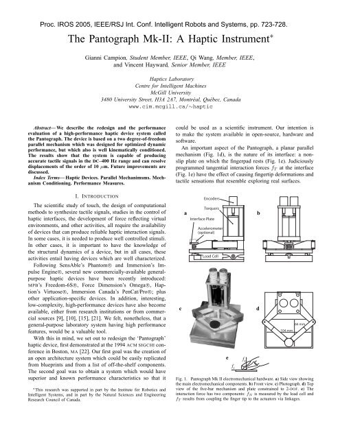
An important aspect of the <strong>Pantograph</strong>, a planar parallel<br />
mechanism (Fig. 1d), is the nature of its interface: a nonslip<br />
plate on which the fingerpad rests (Fig. 1e). Judiciously<br />
programmed tangential interaction forces f T at the interface<br />
(Fig. 1e) have the effect of causing fingertip deformations and<br />
tactile sensations that resemble exploring real surfaces.<br />
I. INTRODUCTION<br />
<strong>The</strong> scientific study of touch, the design of computational<br />
methods to synthesize tactile signals, studies in the control of<br />
haptic interfaces, the development of force reflecting virtual<br />
environments, and other activities, all require the availability<br />
of devices that can produce reliable haptic interaction signals.<br />
In some cases, it is needed to produce well controlled stimuli.<br />
In other cases, it is important to have the knowledge of<br />
the structural dynamics of a device, but in all cases, these<br />
activities entail having devices which are well characterized.<br />
Following SensAble’s Phantom R○ and Immersion’s Impulse<br />
Engine R○, several new commercially-available generalpurpose<br />
haptic devices have been recently introduced:<br />
MPB’s Freedom-6S R○, Force Dimension’s Omega R○, Haption’s<br />
Virtuose R○, Immersion Canada’s PenCat/Pro R○; plus<br />
other application-specific devices. In addition, interesting,<br />
low-complexity, high-performance devices have also become<br />
available, either from research institutions or from commercial<br />
sources [9], [10], [15], [21]. We felt, nonetheless, that a<br />
general-purpose laboratory system having high performance<br />
features, would be a valuable tool.<br />
With this in mind, we set out to redesign the ‘<strong>Pantograph</strong>’<br />
haptic device, first demonstrated at the 1994 ACM SIGCHI conference<br />
in Boston, MA [22]. Our first goal was the creation of<br />
an open architecture system which could be easily replicated<br />
from blueprints and from a list of off-the-shelf components.<br />
<strong>The</strong> second goal was to obtain a system which would have<br />
superior and known performance characteristics so that it<br />
∗ This research was supported in part by the Institute for Robotics and<br />
Intelligent Systems, and in part by the Natural Sciences and Engineering<br />
Research Council of Canada.<br />
c<br />
a<br />
Encoders<br />
Torquers<br />
Interface Plate<br />
Accelerometer<br />
(optional)<br />
Load Cell<br />
e<br />
f T<br />
f N<br />
b<br />
d<br />
104 mm<br />
66 mm<br />
Fig. 1. <strong>Pantograph</strong> <strong>Mk</strong> <strong>II</strong> electromechanical hardware. a) Side view showing<br />
the main electromechanical components. b) Front view. c) Photograph. d) Top<br />
view of the five-bar mechanism and plate constrained to 2-DOF. e) <strong>The</strong><br />
interaction force has two components: f N is measured by the load cell and<br />
f T results from coupling the finger tip to the actuators via linkages.
<strong>II</strong>. COMPONENTS<br />
a) Mechanical Structure: <strong>The</strong> mechanical design was<br />
not changed from the original device. <strong>The</strong> dimensions, as<br />
well as the shape of the links, were determined from dynamic<br />
performance considerations [13], rather than from kinetostatic<br />
considerations [24]. Staticallly, the structure must resist bending<br />
when loaded vertically. <strong>The</strong> proximal links (Fig. 2a) have<br />
a pocketed box design which gives them the structure of a<br />
wishbone horizontally where they are dynamically loaded and<br />
otherwise of a hollow beam for torsional static strength. <strong>The</strong><br />
distal links (Fig. 2b) have an axial dynamic load and behave<br />
like cantilevers under the vertical static load, therefore they<br />
have a tapered shape to reduce weight.<br />
Fig. 2.<br />
Proc. IROS 2005, IEEE/RSJ Int. Conf. Intelligent Robots and Systems, pp. 723-728.<br />
a<br />
b<br />
Internal structure of the beams. a) Proximal link. b) Distal Link.<br />
resolution over the workspace if their signal was unprocessed.<br />
<strong>The</strong>se were replaced by optical rotary incremental encoders.<br />
Two models were evaluated that had the required resolution<br />
and form factor. Models from Gurley Precision <strong>Instrument</strong>s<br />
Inc. (model R119S01024Q5L16B188P04MN; 65,536 CPR)<br />
and MicroE Systems Inc. (model M1520S-40-R1910-HA;<br />
100,000 CPR) both gave good results. <strong>The</strong> Gurley sensors are<br />
less expensive and easier to commission while the MicroE<br />
sensors require alignment and protective custom housing.<br />
f) Electronics: An integrated 4-channel “hardware-inthe-loop”<br />
PCI card from Quanser Inc. (model Q4) with<br />
24-bit encoder counters, unbuffered, low delay analog-todigital/digital-to-analog<br />
channels proved to be a convenient<br />
and cost effective solution (read encoders, read acceleration<br />
and force signal, write actuator currents) that could support<br />
two devices. <strong>The</strong> current amplifier design is crucial given<br />
the observed variation of the motor winding resistance due<br />
to commutation. Low gain current amplifiers built around<br />
the NS power chip LM12CL proved to be only partially<br />
effective. Better performance should be provided in the future<br />
by Quanser’s LCAM amplifiers.<br />
b) Normal Force Sensing: To render arbitrary virtual<br />
surface interaction forces, the normal component of the force<br />
must be known. A sensor could have been put in the plate,<br />
however, locating the sensor (loadcell Omega Engineering<br />
model LCKD-5; conditioner Newport Electronics model INFS-<br />
0010-DC-7) under the entire device is also possible, since<br />
the normal force is entirely due to the user and hence has<br />
low bandwidth. This way, the force sensor does not ‘see’ any<br />
inertial forces (a tip mounted force sensor could be sensitive<br />
to acceleration and give erroneous readings). <strong>The</strong> static load<br />
due to the weight of the device was eliminated by locating<br />
the hinge under the center of mass (Fig. 1a).<br />
c) Accelerometer: To measure the device transfer function,<br />
to provide detailed information about the high-frequency<br />
movements of the plate for use in other experiments (for<br />
example involving acceleration feedback to render textures<br />
or shock sensations, or to investigate the coupled dynamics<br />
of the finger pad), a dual-axis MEMS accelerometer (Analog<br />
Device; model ADXL250) was embedded in an interchangeable<br />
plate (Fig. 1a).<br />
d) Motors: Two conventional coreless DC motors<br />
(Maxon RE-25 graphite brushes) are used as torquers. Although<br />
this solution is clearly suboptimal, it was used for<br />
simplicity and will be further discussed in the Section V.<br />
We experimented with both graphite and metal brushes. <strong>The</strong><br />
friction due to metal brushes is lower, but the electrical<br />
coupling they provide at low speeds with the windings is<br />
not as good as with graphite brushes. It was observed that<br />
the electrical resistance varied so greatly and so rapidly<br />
from one commutator blade to the next that current feedback<br />
was ineffective to compensate for this variation, resulting in<br />
noticeable transient drops in the torque.<br />
e) Position Sensors: <strong>The</strong> servo quality potentiometers<br />
used in the original <strong>Pantograph</strong> could only provide 10 bits of<br />
<strong>II</strong>I. KINEMATICS<br />
<strong>The</strong> kinematic structure is a five-bar planar linkage represented<br />
in Fig 3. <strong>The</strong> end-plate is located at point P 3 and<br />
moves in a plane with two degree-of-freedom with respect to<br />
the ground link, where the actuators and sensors are located<br />
at P 1 and P 5 . <strong>The</strong> configuration of the device is determined<br />
by the position of the two angles θ 1 and θ 5 and the force at<br />
the tool tip P 3 is due to torques applied at joints 1 and 5.<br />
<strong>The</strong> nominal values of the link lengths a i are in mm:<br />
A. Direct Kinematics<br />
a nom = [63 75 75 63 25] ⊤ .<br />
<strong>The</strong> direct kinematics problem consists of finding the<br />
position of point P 3 from the two sensed joint angles θ 1 and<br />
θ 5 . <strong>The</strong> base frame is set so that its z axis passes through P 1 .<br />
It was in the past solved using various approaches, the latest<br />
provided in [6]. <strong>The</strong>se approaches all share the observation<br />
that P 3 is at the intersection of two circles, the centers and<br />
the radii of which are known. <strong>The</strong> circles of radii a 2 and a 3<br />
are centered at:<br />
P 2 (x 2 , y 2 ) = [a 1 cos(θ 1 ), a 1 sin(θ 1 )] ⊤ , and (1)<br />
P 4 (x 4 , y 4 ) = [a 4 cos(θ 5 ) − a 5 , a 4 sin(θ 5 )] ⊤ . (2)<br />
and intersect at two points corresponding to two configurations.<br />
<strong>The</strong> device, however, always operates in the configuration<br />
that has the largest y. We used a geometric approach<br />
to find them. Let P 3 = (x 3 , y 3 ) and P h = (x h , y h ) be the<br />
intersection between the segment P 2 P 4 and the height of<br />
triangle P 2 P 3 P 4 .
Proc. IROS 2005, IEEE/RSJ Int. Conf. Intelligent Robots and Systems, pp. 723-728.<br />
We find<br />
‖P 2 − P h ‖ = (a2 2 − a 2 3 + ‖P 4 − P 2 ‖ 2 )<br />
,<br />
(2‖P 4 − P 2 ‖)<br />
(3)<br />
P h = P 2 + ‖P 2 − P h ‖<br />
‖P 2 − P 4 ‖ (P 4 − P 2 ),<br />
√<br />
(4)<br />
‖P 3 − P h ‖ = a 2 2 − ‖P 2 − P h ‖ 2 . (5)<br />
<strong>The</strong> end effector position P 3 (x 3 , y 3 ) is then given by<br />
x 3 = x h ± ‖P 3 − P h ‖<br />
‖P 2 − P 4 ‖ (y 4 − y 2 ), (6)<br />
y 3 = y h ∓ ‖P 3 − P h ‖<br />
‖P 2 − P 4 ‖ (x 4 − x 2 ). (7)<br />
<strong>The</strong> useful solution has a positive sign in Eq. (6) and negative<br />
sign in Eq. (7). Since in the workspace x 4 < x 2 , the solution<br />
with a negative sign yields larger y.<br />
Fig. 3.<br />
Model of the kinematics used to compute the direct problem.<br />
B. Inverse Kinematics<br />
Parallel manipulators frequently have an inverse kinematics<br />
problem that is simpler than the direct kinematics problem.<br />
<strong>The</strong> <strong>Pantograph</strong> is no exception. <strong>The</strong> problem is to find the<br />
angles θ 1 and θ 5 given the position of point P 3 . A pentagon<br />
can be divided into three triangles, see Fig. 4 which makes<br />
the solution straightforward:<br />
where<br />
θ 1 = π − α 1 − β 1 , θ 5 = α 5 + β 5 , (8)<br />
(<br />
)<br />
a 2 1 − a 2 2 + ‖P 1 , P 3 ‖<br />
α 1 = arccos √ , (9)<br />
2a 1 ‖P1 , P 3 ‖<br />
β 1 = atan2 (y 3 , −x 3 ), (10)<br />
(<br />
)<br />
a 2 4 − a 2 3 + ‖P 5 , P 3 ‖<br />
β 5 = arccos √ , (11)<br />
2a 4 ‖P5 , P 3 ‖<br />
α 5 = atan2 (y 3 , x 3 + a 5 ). (12)<br />
This solves the inverse kinematics for a generic <strong>Pantograph</strong><br />
with arm lengths a i , as long as the device is in a configuration<br />
such that α 1 > 0 and β 5 > 0, which puts it in the permitted<br />
workspace.<br />
Fig. 4.<br />
C. Differential Kinematics<br />
Dividing the pentagon into three triangles.<br />
<strong>The</strong> Jacobian matrix can be found by direct differentiation<br />
of the direct kinematic map with respect to the actuated joints<br />
θ 1 and θ 5 :<br />
J =<br />
[ ]<br />
∂x3 /∂θ 1 ∂x 3 /∂θ 5<br />
=<br />
∂y 3 /∂θ 1 ∂y 3 /∂θ 5<br />
[ ]<br />
∂1 x 3 ∂ 5 x 3<br />
∂ 1 y 3 ∂ 5 y 3<br />
(13)<br />
where ∂ i· denotes the partial derivative with respect to θ i . Let<br />
d = ‖P 2 − P 4 ‖, b = ‖P 2 − P h ‖ and h = ‖P 3 − P h ‖.<br />
Applying the chain rule to Eqs. (6) and (7):<br />
∂ 1 x 2 = a 1 sin(θ 1 ), ∂ 1 y 2 = a 1 cos(θ 1 ), (14)<br />
∂ 5 x 4 = a 4 sin(θ 5 ), ∂ 5 y 4 = a 4 cos(θ 5 ), (15)<br />
∂ 1 y 4 = ∂ 1 x 4 = ∂ 5 y 2 = ∂ 5 x 2 = 0, ∂ i h = −b∂ i b/h (16)<br />
∂ i d = (x 4 − x 2 )(∂ i x 4 −∂ i x 2 )+(y 4 − y 2 )(∂ i y 4 −∂ i y 2 )<br />
(17)<br />
d<br />
∂ i b = ∂ i d − ∂ id(a 2 2 − a 2 3 + d 2 )<br />
2d 2 (18)<br />
∂ i y h = ∂ i y 2<br />
+ ∂ ib d − ∂ i d b<br />
d 2 (y 4 − y 2 ) + b d (∂ iy 4 − ∂ i y 2 ) (19)<br />
∂ i x h = ∂ i x 2<br />
+ ∂ ib d − ∂ i d b<br />
d 2 (x 4 − x 2 ) + b d (∂ ix 4 − ∂ i x 2 ) (20)<br />
∂ i y 3 = ∂ i y h<br />
− h d (∂ ix 4 − ∂ i x 2 ) − ∂ ih d − ∂ i d h<br />
d 2 (x 4 − x 2 ) (21)<br />
∂ i x 3 = ∂ i x h<br />
+ h d (∂ iy 4 − ∂ i y 2 ) + ∂ ih d − ∂ i d h<br />
d 2 (y 4 − y 2 ) (22)<br />
D. Kinematic Conditioning<br />
All entries of the Jacobian have the dimension of lengths<br />
mapping angular velocities ω = [ θ ˙ 1 θ˙<br />
5 ] ⊤ to linear velocities<br />
v = [ x˙<br />
3 y˙<br />
3 ] ⊤ : v = J ω. Thus, the 2-norm of the Jacobian<br />
matrix (which also is a length) has the physical meaning of<br />
scaling the sensor nominal resolution to the nominal resolution<br />
of the device. <strong>The</strong> Jacobian matrix is well conditioned on<br />
all the workspace and the device becomes isotropic at (Fig. 5):<br />
(<br />
)<br />
θ 1 iso =arccos − 25<br />
126 + 25√ 2<br />
, θ 5 iso = π − θ 1 iso (23)<br />
42<br />
corresponding to the point P iso ≃ (−12.5, 101.2) in Fig. 5.<br />
At this point the two distal links intersect orthogonally at
Proc. IROS 2005, IEEE/RSJ Int. Conf. Intelligent Robots and Systems, pp. 723-728.<br />
the tip and the end effector is equidistant from the actuated<br />
joints. Here, the Jacobian matrix maps disks in the angular<br />
velocity joint space to disks in the tip velocity space. <strong>The</strong>re<br />
are just two such points. <strong>The</strong> other point which has a negative<br />
y is not used. <strong>The</strong> isotropic region is near the edge of the<br />
worskspace but this is an acceptable compromise given that<br />
the main objective is dynamic performance. <strong>The</strong> device, as<br />
dimensioned, has a large region of dynamic near-isotropy<br />
spreading over most of the workspace [13].<br />
y (mm)<br />
40<br />
60<br />
80<br />
3.25<br />
2.55<br />
1.95<br />
1.45<br />
100<br />
1.01<br />
40 20 0 -20 -40 -60<br />
x (mm)<br />
Fig. 5. Condition number of the Jacobian of the <strong>Pantograph</strong> over the<br />
workspace. <strong>The</strong> device is isotropic at the point P iso .<br />
If ‖ · ‖ 2 denotes the largest singular value of a matrix, then<br />
expression:<br />
‖∆X‖ ≤ ‖J‖ 2 ‖[∆θ 1 ∆θ 5 ] ⊤ ‖ (24)<br />
where ∆X = [∆x ∆y] ⊤ is the resolution of the device and<br />
∆θ i the resolution of an encoder. This allows us to plot the<br />
ideal resolution of the device in Fig. 6 for the case where<br />
encoders with 65K CPR are used.<br />
y (mm)<br />
40<br />
60<br />
80<br />
100<br />
9 9<br />
8.6<br />
9<br />
40 20 0 -20 -40 -60<br />
x (mm)<br />
Fig. 6. Resolution of the <strong>Pantograph</strong> in the workspace, measurement unit<br />
is the µm. <strong>The</strong> device is equipped with two√ encoders with 2 16 counts per<br />
revolution, the resolution is ‖∆X‖ = ‖J‖ 2 2<br />
2π<br />
2 16 .<br />
E. Calibration<br />
Since the angles are measured by incremental encoders, the<br />
origin needs to be calibrated at system startup. <strong>The</strong> workspace<br />
of the device is mechanically limited to a rectangular area<br />
which can be used for this purpose. In a first maneuver, point<br />
P 3 is brought by the user to the bottom left corner of the<br />
workspace to roughly calibrate the encoders. <strong>The</strong> user then<br />
proceeds to acquire many calibration points by sliding the end<br />
effector along the four edges (bottom, right, top, left). Points<br />
12<br />
11<br />
10<br />
acquired on the bottom edge all have the same y coordinate,<br />
so on this edge, P i↓<br />
3 = (x i 3, y ↓ ) where y ↓ is the known<br />
common value of the coordinate, and similarly for the other<br />
edges: y ↑ for the top edge, x ← for the left edge, and x → for<br />
the right.<br />
Call the θ1 i and θ5, i the measurements acquired. <strong>The</strong> components<br />
of the direct kinematic function are x 3 and y 3 :<br />
P 3 = [x 3 (θ 1 , θ 5 ) y 3 (θ 1 , θ 5 )] ⊤ . <strong>The</strong> device can be calibrated<br />
by minimizing the error function<br />
E = ∑ N ↓<br />
i=1 [y↓ − y 3 (θ i↓<br />
1 + θ0 1, θ i↓<br />
5 + θ0 5)] 2 +<br />
∑ N→<br />
i=1 [x→ x 3 (θ1 i→ + θ1, 0 θ5 i→ + θ5)] 0 2 +<br />
∑ N↑<br />
i=1 [y↑ − y 3 (θ i↑<br />
1 + θ0 1, θ i↑<br />
5 + θ0 5)] 2 +<br />
∑ N←<br />
i=1 [x← − x 3 (θ1 i← + θ1, 0 θ5 i← + θ5)] 0 2 , (25)<br />
over the zero positions θ1 0 and θ5: 0 min θ 0<br />
1 ,θ5 0 E. This is accomplished<br />
using the Levenberg-Marquardt algorithm [8]. <strong>The</strong><br />
results are satisfying since the two offset angles are found<br />
with an uncertainty of 6-7 counts which can be attributed<br />
to backlash in the joints 2 and 4 as further discussed in<br />
Section IV-B.<br />
IV. RESULTS<br />
<strong>The</strong> importance of the static and dynamic behavior of<br />
haptic devices, accounting for the mechanical structure, transmission<br />
and drive electronics has been well recognized by<br />
device designers [1], [2], [7], [14], [20], [23].<br />
Guidelines for measuring the performance characteristics<br />
of force feedback haptic devices were documented in [12].<br />
Among these guidelines two are particularly important, in<br />
addition to the usual requirement of minimizing interference<br />
with the process being measured. <strong>The</strong> first specifies that<br />
the characteristics must be measured where the device is<br />
in contact with the skin. <strong>The</strong> second recognizes the fact<br />
that a haptic device has a response that depends on the<br />
load. <strong>The</strong>refore, load reflecting the conditions of actual use<br />
must be applied during the measurements. From this view<br />
point, measurement of the system response from the actuator<br />
side and without a load, as it is sometimes done (e.g. [4]),<br />
fails to provide the sought information. A useful actuatorside<br />
technique that quantifies the structural properties of a<br />
device in terms of a “structural deformation ratio” (SRD) was<br />
nevertheless suggested [19]. It was not used here since the<br />
complete system response provides richer information.<br />
A. Experimental System Response<br />
<strong>The</strong> frequency response (from amplifier current command<br />
to acceleration at the tip) was measured with a system<br />
analyzer (DSP Technology Inc., SigLab model 20-22) using<br />
chirp excitation. This technique was used because it is more<br />
precise and more robust to nonlinearities (and more time<br />
consuming) than an ARMAX procedure.<br />
Measurements were performed under three conditions. <strong>The</strong><br />
first corresponded to the unloaded condition. In order to<br />
prevent the device from drifting away during identification, it<br />
was held in place by a loosely taught rubber band. <strong>The</strong> second
Proc. IROS 2005, IEEE/RSJ Int. Conf. Intelligent Robots and Systems, pp. 723-728.<br />
condition was created by lightly touching the interface plate<br />
while the response was measured. In the third condition, the<br />
device was loaded by pressing firmly on it.<br />
An ideal device should have a uniform gain across all<br />
frequencies (and would have to a SDR index of 1.0 [19]).<br />
Fig. 7 shows all three responses on the same graph but offset<br />
by 10 dB for clarity. <strong>The</strong> response was indeed flat over a wide<br />
bandwidth (40 to 300 Hz). But irregularities occured in the<br />
low and the high frequency regions.<br />
In the low frequency region, the rise in gain for the<br />
“unloaded response” was most probably due to presence of<br />
the rubber band and can be ignored. However contact with<br />
a finger creates a low Q resonance (Q factor 2 to 3) which<br />
shifted up in frequency when the finger pressed harder. This<br />
could be explained by the nonlinear nature of tissues. <strong>The</strong>se<br />
observations conspire to indicate that indeed, it would be<br />
difficult to reduce the finger to that of a linear time invariant<br />
system without risking to oversimplify the dynamics of the<br />
actual system [10], [18].<br />
In the high frequency region, there were two notable<br />
events in the response. <strong>The</strong> “unloaded response” first shows<br />
what is the typical fingerprint of a sharp, low-loss structural<br />
resonance (pole-zero pair) in the 400-500 Hz band. This could<br />
be attributed to flexibility inside the motor as these often<br />
emit acoustic noise at this frequency upon torque transients<br />
(this is also the case of all haptic interfaces using the same<br />
“bell coreless” motors). As the finger presses harder on the<br />
interface, this resonance is progressively masked by the load<br />
but probably continues to occur, but is unseen at the tip. Now,<br />
what is more difficult to explain are the additional events in<br />
the 900 Hz region, which instead of being attenuated by a<br />
larger load as one would expect, are actually enhanced to<br />
reach up to 30 dB of gain, a rather large magnitude indeed.<br />
If these were due to structural resonance of the linkages,<br />
then one would observe a shift in frequency due to nonlinear<br />
buckling. But it is not the case. This problem will be further<br />
discussed in Section V. In the meantime we established that<br />
the device can reliably be used in the DC–400 Hz range<br />
provided that proper roll-off filters are used [3].<br />
B. Resolution<br />
We estimated the actual device resolution using the setup<br />
shown in Fig. 8a. A micropositioner was connected to joint<br />
3 so it could back-drive the device along the y axis in the<br />
vicinity of point P iso . Backlash and other joint imperfections<br />
were likely to deteriorate the resolution of the device but<br />
should not be considered first. To minimize their influence, a<br />
constant torque was applied by the motor to preload the joints.<br />
Fig 8b shows the encoders values when the tip is moved<br />
by 50 µm. This verifies the resolution determined from the<br />
analysis of the Jacobian matrix.<br />
V. CONCLUSION AND DISCUSSION<br />
This paper has described the redesign of the <strong>Pantograph</strong><br />
haptic device with a view to increase its performance so it<br />
would be capable of providing high quality haptic rendering.<br />
Amplitude (dB)<br />
40<br />
30<br />
20<br />
10<br />
0<br />
Finger (press hard)<br />
Finger (press lightly)<br />
Loose rubber band<br />
40 100 400 1000<br />
Frequency (Hz)<br />
Fig. 7. Frequency Response of the device when an identical signal is sent<br />
to both the amplifiers to create an horizontal movement. <strong>The</strong> intensity of the<br />
movement is measured with an accelerometer approximately parallel to the<br />
movement. <strong>The</strong> response curves relative to the finger are shifted of +10 dB<br />
(light pressure) and +20 dB (hard pressure).<br />
a<br />
b<br />
0.006<br />
0.004<br />
0.002<br />
0.000<br />
-0.002<br />
-0.004<br />
-0.006<br />
Fig. 8. a) Setup used to verify resolution. b) Encoder reading during a linear<br />
movement of 50 µm. <strong>The</strong> plot shows that there are 5 or 6 ticks, matching<br />
the analysis made with the Jacobian.<br />
Its performance was evaluated and found to meet the initial<br />
expectations of uniform and wide bandwidth response. However,<br />
while the device operates very well, several points still<br />
need attention. <strong>The</strong> manner in which they can be addressed<br />
is now discussed by order of increasing implementation<br />
difficulty.<br />
1) <strong>The</strong> backlash in the joints in certain conditions, particularly<br />
when the plate is not statically loaded, can reach<br />
several encoders ticks. <strong>The</strong> cause was simple to find<br />
and so will be the solution to eliminate it. <strong>The</strong> present<br />
bearings were specified of ordinary quality. In fact, their<br />
backlash specifications match the observations. <strong>The</strong>y<br />
should be replaced by higher quality bearings since<br />
clearly this is a limiting factor.<br />
2) <strong>The</strong> device is machined out of aluminum. It is possible<br />
that the metallic structure participates in the observed<br />
unwanted high frequency resonance. Composite materials<br />
could be used to manufactured haptic devices with<br />
structural properties designed to optimize their response<br />
(e.g. adjust for critical damping) [17].
Proc. IROS 2005, IEEE/RSJ Int. Conf. Intelligent Robots and Systems, pp. 723-728.<br />
3) <strong>The</strong> device should incorporate a source of calibrated<br />
viscous damping [5], something which is the subject of<br />
on-going work.<br />
4) “Bell coreless” motors work well but are less than<br />
ideal for haptic device applications due to (1) their<br />
sharp internal resonance characterized in this paper,<br />
and (2) use of un-needed brushes in a limited angle<br />
application [24]. Motors having an absence of torque<br />
ripple, absence of cyclical reluctant torque (cogging),<br />
optimized structural properties, and absence of friction<br />
(in addition to high torque, of course) should be designed<br />
specifically for this application. Recent proposals<br />
for electronic compensation of the injurious properties<br />
of motors designed for other purposes fall short of our<br />
requirements in this respect [16].<br />
Finally, we hope to be able to release the system publicly<br />
in a near future, even if not all the points discussed above are<br />
fully addressed. At the present time however, the system is<br />
in use to carry out studied in high fidelity friction and texture<br />
synthesis techniques [3], [11].<br />
ACKNOWLEDGMENTS<br />
Qi Wang and Gianni Campion thank PRECARN Inc. for<br />
scholarships. <strong>The</strong> authors would also like to thank Hsin-<br />
Yun Yao for assistance in PCB design and manufacturing and<br />
Andrew Havens Gosline for insightful comments on an earlier<br />
draft of this paper.<br />
REFERENCES<br />
[1] B. D. Adelstein and M. J. Rosen. Design and implementation of a<br />
force reflective manipulandum for manual control research. In Proc.<br />
Advances in Robotics, ASME Winter Annual Meeting, volume DSC-42,<br />
pages 1–12, 1992.<br />
[2] P. Buttolo and B. Hannaford. Advantages of actuation redundancy for<br />
the design of haptic-displays. In Proc. ASME Fourth Annual Symposium<br />
on <strong>Haptic</strong> Interfaces for Virtual Environments and Teleoperator<br />
Systems, volume DSC-57-2, pages 623–630, 1995.<br />
[3] G. Campion and V. Hayward. Fundamental limits in the rendering of<br />
virtual haptic textures. In Proc. World<strong>Haptic</strong>s Conference 2005, pages<br />
263–270, 2005.<br />
[4] M.C. Cavusoglu, D. Feygin, and F. Tendick. A critical study of<br />
the mechanical and electrical properties of the PHANToM haptic<br />
interface and improvements for high performance control. Presence:<br />
Teleoperators and Virtual Environments, 11(6):555–568, 2002.<br />
[5] J. E. Colgate and G. G. Schenkel. Passivity of a class of sampleddata<br />
systems: application to haptic interfaces. J. of Robotic Systems,<br />
14(1):37–47, 1997.<br />
[6] D. DiFilippo and D. K. Pai. <strong>The</strong> AHI: An audio and haptic interface for<br />
contact interactions. In Proc. UIST’00, 13th Annual ACM Symposium<br />
on User Interface Software and Technology, 2000. available online<br />
http://www.acm.org/uist/uist2000/fp.main.html.<br />
[7] R. E. Ellis, O. M. Ismaeil, and M. Lipsett. Design and evaluation of<br />
a high-performance prototype planar haptic interface. In Proc. ASME<br />
Advances in Robotics, Mechatronics, and <strong>Haptic</strong> Interfaces, volume<br />
DSC-9, pages 55–64, 1993.<br />
[8] R. Fletcher. Practical Methods of Optimization. John Wiley & Sons,<br />
1987.<br />
[9] D. Grant. Two new commercial haptic rotary controllers. In Proc.<br />
Eurohaptics, page 451, 2004.<br />
[10] C. J. Hasser and M. R. Cutkosky. System identification of the human<br />
hand grasping a haptic knob. In Proc. 10th Symposium on <strong>Haptic</strong><br />
Interfaces for Virtual Environment and Teleoperator Systems (HAPTICS<br />
’02), 2002.<br />
[11] V. Hayward and B. Armstrong. A new computational model of<br />
friction applied to haptic rendering. In P. Corke and J. Trevelyan,<br />
editors, Experimental Robotics VI, pages 403–412. Springer Verlag,<br />
2000. Lecture Notes in Control and Information Sciences 250.<br />
[12] V. Hayward and O. R. Astley. Performance measures for haptic<br />
interfaces. In G. Giralt and G. Hirzinger, editors, Robotics Research:<br />
<strong>The</strong> 7th International Symposium, pages 195–207. Springer Verlag,<br />
1996.<br />
[13] V. Hayward, J. Choksi, G. Lanvin, and C. Ramstein. Design and multiobjective<br />
optimization of a linkage for a haptic interface. In J. Lenarcic<br />
and B. Ravani, editors, Advances in Robot Kinematics, pages 352–359.<br />
Kluver Academic, 1994.<br />
[14] V. Hayward, P. Gregorio, O. Astley, S. Greenish, M. Doyon, L. Lessard,<br />
J. McDougall, I. Sinclair, S. Boelen, X. Chen, J.-P. Demers, J. Poulin,<br />
I, Benguigui, N. Almey, B. Makuc, and X. Zhang. Freedom-7: A high<br />
fidelity seven axis haptic device with application to surgical training.<br />
In A. Casals and A. T. de Almeida, editors, Experimental Robotics V,<br />
pages 445–456. Springer Verlag, 1998. Lecture Notes in Control and<br />
Information Science 232.<br />
[15] Quanser Inc. 3-DOF planar <strong>Pantograph</strong>. In Quanser Product Information,<br />
2004. http://www.quanser.com.<br />
[16] D. A. Lawrence, L. Y. Pao, A. C. White, and W. Xu. Low cost<br />
actuator and sensor for high-fidelity haptic interfaces. In Proc. 12th<br />
International Symposium on <strong>Haptic</strong> Interfaces for Virtual Environment<br />
and Teleoperator Systems (HAPTICS’04), pages 74–81, 2004.<br />
[17] J. McDougal, L. B. Lessard, and V. Hayward. Applications of advanced<br />
materials to robotic design: <strong>The</strong> freedom-7 haptic hand controller.<br />
In Proc. Eleventh International Conference on Composite Materials<br />
(ICCM-11), 1997.<br />
[18] T. E. Milner and D. W. Franklin. Characterization of multijoint finger<br />
stiffness: Dependence on finger posture and force direction. IEEE T.<br />
on Biomedical Engineering, 45(11):1363–1375, 1998.<br />
[19] M. Moreyra and B. Hannaford. A practical measure of dynamic<br />
response of haptic devices. In Proc. IEEE International Conference<br />
on Robotics and Automation, pages 369–374, 1998.<br />
[20] J. B. Morrell and J. K. Salisbury. Performance measurements for robotic<br />
actuators. In Proc. ASME Dynamics Systems and Control Division,<br />
volume DSC-58, pages 531–537, 1996.<br />
[21] J. Murayama, L. Bougrila, Y.L. Luo, K. Akahane, S. Hasegawa,<br />
B. Hirsbrunner, and M. Sato. Spidar G&G: A new two-handed haptic<br />
interface for bimanual VR interaction. In Proc. Eurohaptics, pages<br />
138–146, 2004.<br />
[22] C. Ramstein and V. Hayward. <strong>The</strong> <strong>Pantograph</strong>: A large workspace<br />
haptic device for a multi-modal human-computer interaction. In Proc.<br />
CHI’94, Conference on Human Factors in Computing Systems, pages<br />
57–58. ACM/SIGCHI Companion-4/94, 1994.<br />
[23] L. Rosenberg. How to assess the quality of force-feedback systems. J.<br />
of Medicine and Virtual Reality, 1(1):12–15, 1995.<br />
[24] S. E. Salcudean and L. Stocco. Isotropy and actuator optimization in<br />
haptic interface design. In Proc. IEEE International Conference on<br />
Robotics & Automation, pages 3107–3113, 2000.


