The Pantograph Mk-II: A Haptic Instrument - CIM - McGill University
The Pantograph Mk-II: A Haptic Instrument - CIM - McGill University
The Pantograph Mk-II: A Haptic Instrument - CIM - McGill University

Create successful ePaper yourself
Turn your PDF publications into a flip-book with our unique Google optimized e-Paper software.
Proc. IROS 2005, IEEE/RSJ Int. Conf. Intelligent Robots and Systems, pp. 723-728.<br />
<strong>The</strong> <strong>Pantograph</strong> <strong>Mk</strong>-<strong>II</strong>: A <strong>Haptic</strong> <strong>Instrument</strong> ∗<br />
Gianni Campion, Student Member, IEEE, Qi Wang, Member, IEEE,<br />
and Vincent Hayward, Senior Member, IEEE<br />
<strong>Haptic</strong>s Laboratory<br />
Centre for Intelligent Machines<br />
<strong>McGill</strong> <strong>University</strong><br />
3480 <strong>University</strong> Street, H3A 2A7, Montréal, Québec, Canada<br />
www.cim.mcgill.ca/∼haptic<br />
Abstract— We describe the redesign and the performance<br />
evaluation of a high-performance haptic device system called<br />
the <strong>Pantograph</strong>. <strong>The</strong> device is based on a two degree-of-freedom<br />
parallel mechanism which was designed for optimized dynamic<br />
performance, but which also is well kinematically conditioned.<br />
<strong>The</strong> results show that the system is capable of producing<br />
accurate tactile signals in the DC–400 Hz range and can resolve<br />
displacements of the order of 10 µm. Future improvements are<br />
discussed.<br />
Index Terms— <strong>Haptic</strong> Devices. Parallel Mechanimsms. Mechanism<br />
Conditioning. Performance Measures.<br />
could be used as a scientific instrument. Our intention is<br />
to make the system available in open-source, hardware and<br />
software.<br />
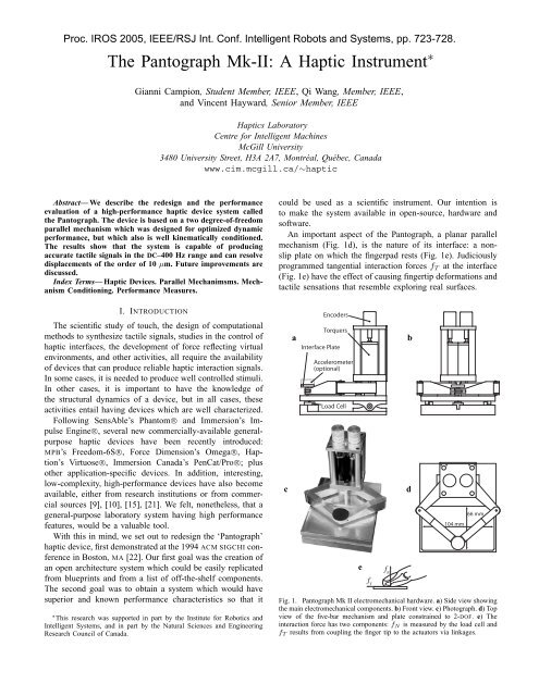
An important aspect of the <strong>Pantograph</strong>, a planar parallel<br />
mechanism (Fig. 1d), is the nature of its interface: a nonslip<br />
plate on which the fingerpad rests (Fig. 1e). Judiciously<br />
programmed tangential interaction forces f T at the interface<br />
(Fig. 1e) have the effect of causing fingertip deformations and<br />
tactile sensations that resemble exploring real surfaces.<br />
I. INTRODUCTION<br />
<strong>The</strong> scientific study of touch, the design of computational<br />
methods to synthesize tactile signals, studies in the control of<br />
haptic interfaces, the development of force reflecting virtual<br />
environments, and other activities, all require the availability<br />
of devices that can produce reliable haptic interaction signals.<br />
In some cases, it is needed to produce well controlled stimuli.<br />
In other cases, it is important to have the knowledge of<br />
the structural dynamics of a device, but in all cases, these<br />
activities entail having devices which are well characterized.<br />
Following SensAble’s Phantom R○ and Immersion’s Impulse<br />
Engine R○, several new commercially-available generalpurpose<br />
haptic devices have been recently introduced:<br />
MPB’s Freedom-6S R○, Force Dimension’s Omega R○, Haption’s<br />
Virtuose R○, Immersion Canada’s PenCat/Pro R○; plus<br />
other application-specific devices. In addition, interesting,<br />
low-complexity, high-performance devices have also become<br />
available, either from research institutions or from commercial<br />
sources [9], [10], [15], [21]. We felt, nonetheless, that a<br />
general-purpose laboratory system having high performance<br />
features, would be a valuable tool.<br />
With this in mind, we set out to redesign the ‘<strong>Pantograph</strong>’<br />
haptic device, first demonstrated at the 1994 ACM SIGCHI conference<br />
in Boston, MA [22]. Our first goal was the creation of<br />
an open architecture system which could be easily replicated<br />
from blueprints and from a list of off-the-shelf components.<br />
<strong>The</strong> second goal was to obtain a system which would have<br />
superior and known performance characteristics so that it<br />
∗ This research was supported in part by the Institute for Robotics and<br />
Intelligent Systems, and in part by the Natural Sciences and Engineering<br />
Research Council of Canada.<br />
c<br />
a<br />
Encoders<br />
Torquers<br />
Interface Plate<br />
Accelerometer<br />
(optional)<br />
Load Cell<br />
e<br />
f T<br />
f N<br />
b<br />
d<br />
104 mm<br />
66 mm<br />
Fig. 1. <strong>Pantograph</strong> <strong>Mk</strong> <strong>II</strong> electromechanical hardware. a) Side view showing<br />
the main electromechanical components. b) Front view. c) Photograph. d) Top<br />
view of the five-bar mechanism and plate constrained to 2-DOF. e) <strong>The</strong><br />
interaction force has two components: f N is measured by the load cell and<br />
f T results from coupling the finger tip to the actuators via linkages.
<strong>II</strong>. COMPONENTS<br />
a) Mechanical Structure: <strong>The</strong> mechanical design was<br />
not changed from the original device. <strong>The</strong> dimensions, as<br />
well as the shape of the links, were determined from dynamic<br />
performance considerations [13], rather than from kinetostatic<br />
considerations [24]. Staticallly, the structure must resist bending<br />
when loaded vertically. <strong>The</strong> proximal links (Fig. 2a) have<br />
a pocketed box design which gives them the structure of a<br />
wishbone horizontally where they are dynamically loaded and<br />
otherwise of a hollow beam for torsional static strength. <strong>The</strong><br />
distal links (Fig. 2b) have an axial dynamic load and behave<br />
like cantilevers under the vertical static load, therefore they<br />
have a tapered shape to reduce weight.<br />
Fig. 2.<br />
Proc. IROS 2005, IEEE/RSJ Int. Conf. Intelligent Robots and Systems, pp. 723-728.<br />
a<br />
b<br />
Internal structure of the beams. a) Proximal link. b) Distal Link.<br />
resolution over the workspace if their signal was unprocessed.<br />
<strong>The</strong>se were replaced by optical rotary incremental encoders.<br />
Two models were evaluated that had the required resolution<br />
and form factor. Models from Gurley Precision <strong>Instrument</strong>s<br />
Inc. (model R119S01024Q5L16B188P04MN; 65,536 CPR)<br />
and MicroE Systems Inc. (model M1520S-40-R1910-HA;<br />
100,000 CPR) both gave good results. <strong>The</strong> Gurley sensors are<br />
less expensive and easier to commission while the MicroE<br />
sensors require alignment and protective custom housing.<br />
f) Electronics: An integrated 4-channel “hardware-inthe-loop”<br />
PCI card from Quanser Inc. (model Q4) with<br />
24-bit encoder counters, unbuffered, low delay analog-todigital/digital-to-analog<br />
channels proved to be a convenient<br />
and cost effective solution (read encoders, read acceleration<br />
and force signal, write actuator currents) that could support<br />
two devices. <strong>The</strong> current amplifier design is crucial given<br />
the observed variation of the motor winding resistance due<br />
to commutation. Low gain current amplifiers built around<br />
the NS power chip LM12CL proved to be only partially<br />
effective. Better performance should be provided in the future<br />
by Quanser’s LCAM amplifiers.<br />
b) Normal Force Sensing: To render arbitrary virtual<br />
surface interaction forces, the normal component of the force<br />
must be known. A sensor could have been put in the plate,<br />
however, locating the sensor (loadcell Omega Engineering<br />
model LCKD-5; conditioner Newport Electronics model INFS-<br />
0010-DC-7) under the entire device is also possible, since<br />
the normal force is entirely due to the user and hence has<br />
low bandwidth. This way, the force sensor does not ‘see’ any<br />
inertial forces (a tip mounted force sensor could be sensitive<br />
to acceleration and give erroneous readings). <strong>The</strong> static load<br />
due to the weight of the device was eliminated by locating<br />
the hinge under the center of mass (Fig. 1a).<br />
c) Accelerometer: To measure the device transfer function,<br />
to provide detailed information about the high-frequency<br />
movements of the plate for use in other experiments (for<br />
example involving acceleration feedback to render textures<br />
or shock sensations, or to investigate the coupled dynamics<br />
of the finger pad), a dual-axis MEMS accelerometer (Analog<br />
Device; model ADXL250) was embedded in an interchangeable<br />
plate (Fig. 1a).<br />
d) Motors: Two conventional coreless DC motors<br />
(Maxon RE-25 graphite brushes) are used as torquers. Although<br />
this solution is clearly suboptimal, it was used for<br />
simplicity and will be further discussed in the Section V.<br />
We experimented with both graphite and metal brushes. <strong>The</strong><br />
friction due to metal brushes is lower, but the electrical<br />
coupling they provide at low speeds with the windings is<br />
not as good as with graphite brushes. It was observed that<br />
the electrical resistance varied so greatly and so rapidly<br />
from one commutator blade to the next that current feedback<br />
was ineffective to compensate for this variation, resulting in<br />
noticeable transient drops in the torque.<br />
e) Position Sensors: <strong>The</strong> servo quality potentiometers<br />
used in the original <strong>Pantograph</strong> could only provide 10 bits of<br />
<strong>II</strong>I. KINEMATICS<br />
<strong>The</strong> kinematic structure is a five-bar planar linkage represented<br />
in Fig 3. <strong>The</strong> end-plate is located at point P 3 and<br />
moves in a plane with two degree-of-freedom with respect to<br />
the ground link, where the actuators and sensors are located<br />
at P 1 and P 5 . <strong>The</strong> configuration of the device is determined<br />
by the position of the two angles θ 1 and θ 5 and the force at<br />
the tool tip P 3 is due to torques applied at joints 1 and 5.<br />
<strong>The</strong> nominal values of the link lengths a i are in mm:<br />
A. Direct Kinematics<br />
a nom = [63 75 75 63 25] ⊤ .<br />
<strong>The</strong> direct kinematics problem consists of finding the<br />
position of point P 3 from the two sensed joint angles θ 1 and<br />
θ 5 . <strong>The</strong> base frame is set so that its z axis passes through P 1 .<br />
It was in the past solved using various approaches, the latest<br />
provided in [6]. <strong>The</strong>se approaches all share the observation<br />
that P 3 is at the intersection of two circles, the centers and<br />
the radii of which are known. <strong>The</strong> circles of radii a 2 and a 3<br />
are centered at:<br />
P 2 (x 2 , y 2 ) = [a 1 cos(θ 1 ), a 1 sin(θ 1 )] ⊤ , and (1)<br />
P 4 (x 4 , y 4 ) = [a 4 cos(θ 5 ) − a 5 , a 4 sin(θ 5 )] ⊤ . (2)<br />
and intersect at two points corresponding to two configurations.<br />
<strong>The</strong> device, however, always operates in the configuration<br />
that has the largest y. We used a geometric approach<br />
to find them. Let P 3 = (x 3 , y 3 ) and P h = (x h , y h ) be the<br />
intersection between the segment P 2 P 4 and the height of<br />
triangle P 2 P 3 P 4 .
Proc. IROS 2005, IEEE/RSJ Int. Conf. Intelligent Robots and Systems, pp. 723-728.<br />
We find<br />
‖P 2 − P h ‖ = (a2 2 − a 2 3 + ‖P 4 − P 2 ‖ 2 )<br />
,<br />
(2‖P 4 − P 2 ‖)<br />
(3)<br />
P h = P 2 + ‖P 2 − P h ‖<br />
‖P 2 − P 4 ‖ (P 4 − P 2 ),<br />
√<br />
(4)<br />
‖P 3 − P h ‖ = a 2 2 − ‖P 2 − P h ‖ 2 . (5)<br />
<strong>The</strong> end effector position P 3 (x 3 , y 3 ) is then given by<br />
x 3 = x h ± ‖P 3 − P h ‖<br />
‖P 2 − P 4 ‖ (y 4 − y 2 ), (6)<br />
y 3 = y h ∓ ‖P 3 − P h ‖<br />
‖P 2 − P 4 ‖ (x 4 − x 2 ). (7)<br />
<strong>The</strong> useful solution has a positive sign in Eq. (6) and negative<br />
sign in Eq. (7). Since in the workspace x 4 < x 2 , the solution<br />
with a negative sign yields larger y.<br />
Fig. 3.<br />
Model of the kinematics used to compute the direct problem.<br />
B. Inverse Kinematics<br />
Parallel manipulators frequently have an inverse kinematics<br />
problem that is simpler than the direct kinematics problem.<br />
<strong>The</strong> <strong>Pantograph</strong> is no exception. <strong>The</strong> problem is to find the<br />
angles θ 1 and θ 5 given the position of point P 3 . A pentagon<br />
can be divided into three triangles, see Fig. 4 which makes<br />
the solution straightforward:<br />
where<br />
θ 1 = π − α 1 − β 1 , θ 5 = α 5 + β 5 , (8)<br />
(<br />
)<br />
a 2 1 − a 2 2 + ‖P 1 , P 3 ‖<br />
α 1 = arccos √ , (9)<br />
2a 1 ‖P1 , P 3 ‖<br />
β 1 = atan2 (y 3 , −x 3 ), (10)<br />
(<br />
)<br />
a 2 4 − a 2 3 + ‖P 5 , P 3 ‖<br />
β 5 = arccos √ , (11)<br />
2a 4 ‖P5 , P 3 ‖<br />
α 5 = atan2 (y 3 , x 3 + a 5 ). (12)<br />
This solves the inverse kinematics for a generic <strong>Pantograph</strong><br />
with arm lengths a i , as long as the device is in a configuration<br />
such that α 1 > 0 and β 5 > 0, which puts it in the permitted<br />
workspace.<br />
Fig. 4.<br />
C. Differential Kinematics<br />
Dividing the pentagon into three triangles.<br />
<strong>The</strong> Jacobian matrix can be found by direct differentiation<br />
of the direct kinematic map with respect to the actuated joints<br />
θ 1 and θ 5 :<br />
J =<br />
[ ]<br />
∂x3 /∂θ 1 ∂x 3 /∂θ 5<br />
=<br />
∂y 3 /∂θ 1 ∂y 3 /∂θ 5<br />
[ ]<br />
∂1 x 3 ∂ 5 x 3<br />
∂ 1 y 3 ∂ 5 y 3<br />
(13)<br />
where ∂ i· denotes the partial derivative with respect to θ i . Let<br />
d = ‖P 2 − P 4 ‖, b = ‖P 2 − P h ‖ and h = ‖P 3 − P h ‖.<br />
Applying the chain rule to Eqs. (6) and (7):<br />
∂ 1 x 2 = a 1 sin(θ 1 ), ∂ 1 y 2 = a 1 cos(θ 1 ), (14)<br />
∂ 5 x 4 = a 4 sin(θ 5 ), ∂ 5 y 4 = a 4 cos(θ 5 ), (15)<br />
∂ 1 y 4 = ∂ 1 x 4 = ∂ 5 y 2 = ∂ 5 x 2 = 0, ∂ i h = −b∂ i b/h (16)<br />
∂ i d = (x 4 − x 2 )(∂ i x 4 −∂ i x 2 )+(y 4 − y 2 )(∂ i y 4 −∂ i y 2 )<br />
(17)<br />
d<br />
∂ i b = ∂ i d − ∂ id(a 2 2 − a 2 3 + d 2 )<br />
2d 2 (18)<br />
∂ i y h = ∂ i y 2<br />
+ ∂ ib d − ∂ i d b<br />
d 2 (y 4 − y 2 ) + b d (∂ iy 4 − ∂ i y 2 ) (19)<br />
∂ i x h = ∂ i x 2<br />
+ ∂ ib d − ∂ i d b<br />
d 2 (x 4 − x 2 ) + b d (∂ ix 4 − ∂ i x 2 ) (20)<br />
∂ i y 3 = ∂ i y h<br />
− h d (∂ ix 4 − ∂ i x 2 ) − ∂ ih d − ∂ i d h<br />
d 2 (x 4 − x 2 ) (21)<br />
∂ i x 3 = ∂ i x h<br />
+ h d (∂ iy 4 − ∂ i y 2 ) + ∂ ih d − ∂ i d h<br />
d 2 (y 4 − y 2 ) (22)<br />
D. Kinematic Conditioning<br />
All entries of the Jacobian have the dimension of lengths<br />
mapping angular velocities ω = [ θ ˙ 1 θ˙<br />
5 ] ⊤ to linear velocities<br />
v = [ x˙<br />
3 y˙<br />
3 ] ⊤ : v = J ω. Thus, the 2-norm of the Jacobian<br />
matrix (which also is a length) has the physical meaning of<br />
scaling the sensor nominal resolution to the nominal resolution<br />
of the device. <strong>The</strong> Jacobian matrix is well conditioned on<br />
all the workspace and the device becomes isotropic at (Fig. 5):<br />
(<br />
)<br />
θ 1 iso =arccos − 25<br />
126 + 25√ 2<br />
, θ 5 iso = π − θ 1 iso (23)<br />
42<br />
corresponding to the point P iso ≃ (−12.5, 101.2) in Fig. 5.<br />
At this point the two distal links intersect orthogonally at
Proc. IROS 2005, IEEE/RSJ Int. Conf. Intelligent Robots and Systems, pp. 723-728.<br />
the tip and the end effector is equidistant from the actuated<br />
joints. Here, the Jacobian matrix maps disks in the angular<br />
velocity joint space to disks in the tip velocity space. <strong>The</strong>re<br />
are just two such points. <strong>The</strong> other point which has a negative<br />
y is not used. <strong>The</strong> isotropic region is near the edge of the<br />
worskspace but this is an acceptable compromise given that<br />
the main objective is dynamic performance. <strong>The</strong> device, as<br />
dimensioned, has a large region of dynamic near-isotropy<br />
spreading over most of the workspace [13].<br />
y (mm)<br />
40<br />
60<br />
80<br />
3.25<br />
2.55<br />
1.95<br />
1.45<br />
100<br />
1.01<br />
40 20 0 -20 -40 -60<br />
x (mm)<br />
Fig. 5. Condition number of the Jacobian of the <strong>Pantograph</strong> over the<br />
workspace. <strong>The</strong> device is isotropic at the point P iso .<br />
If ‖ · ‖ 2 denotes the largest singular value of a matrix, then<br />
expression:<br />
‖∆X‖ ≤ ‖J‖ 2 ‖[∆θ 1 ∆θ 5 ] ⊤ ‖ (24)<br />
where ∆X = [∆x ∆y] ⊤ is the resolution of the device and<br />
∆θ i the resolution of an encoder. This allows us to plot the<br />
ideal resolution of the device in Fig. 6 for the case where<br />
encoders with 65K CPR are used.<br />
y (mm)<br />
40<br />
60<br />
80<br />
100<br />
9 9<br />
8.6<br />
9<br />
40 20 0 -20 -40 -60<br />
x (mm)<br />
Fig. 6. Resolution of the <strong>Pantograph</strong> in the workspace, measurement unit<br />
is the µm. <strong>The</strong> device is equipped with two√ encoders with 2 16 counts per<br />
revolution, the resolution is ‖∆X‖ = ‖J‖ 2 2<br />
2π<br />
2 16 .<br />
E. Calibration<br />
Since the angles are measured by incremental encoders, the<br />
origin needs to be calibrated at system startup. <strong>The</strong> workspace<br />
of the device is mechanically limited to a rectangular area<br />
which can be used for this purpose. In a first maneuver, point<br />
P 3 is brought by the user to the bottom left corner of the<br />
workspace to roughly calibrate the encoders. <strong>The</strong> user then<br />
proceeds to acquire many calibration points by sliding the end<br />
effector along the four edges (bottom, right, top, left). Points<br />
12<br />
11<br />
10<br />
acquired on the bottom edge all have the same y coordinate,<br />
so on this edge, P i↓<br />
3 = (x i 3, y ↓ ) where y ↓ is the known<br />
common value of the coordinate, and similarly for the other<br />
edges: y ↑ for the top edge, x ← for the left edge, and x → for<br />
the right.<br />
Call the θ1 i and θ5, i the measurements acquired. <strong>The</strong> components<br />
of the direct kinematic function are x 3 and y 3 :<br />
P 3 = [x 3 (θ 1 , θ 5 ) y 3 (θ 1 , θ 5 )] ⊤ . <strong>The</strong> device can be calibrated<br />
by minimizing the error function<br />
E = ∑ N ↓<br />
i=1 [y↓ − y 3 (θ i↓<br />
1 + θ0 1, θ i↓<br />
5 + θ0 5)] 2 +<br />
∑ N→<br />
i=1 [x→ x 3 (θ1 i→ + θ1, 0 θ5 i→ + θ5)] 0 2 +<br />
∑ N↑<br />
i=1 [y↑ − y 3 (θ i↑<br />
1 + θ0 1, θ i↑<br />
5 + θ0 5)] 2 +<br />
∑ N←<br />
i=1 [x← − x 3 (θ1 i← + θ1, 0 θ5 i← + θ5)] 0 2 , (25)<br />
over the zero positions θ1 0 and θ5: 0 min θ 0<br />
1 ,θ5 0 E. This is accomplished<br />
using the Levenberg-Marquardt algorithm [8]. <strong>The</strong><br />
results are satisfying since the two offset angles are found<br />
with an uncertainty of 6-7 counts which can be attributed<br />
to backlash in the joints 2 and 4 as further discussed in<br />
Section IV-B.<br />
IV. RESULTS<br />
<strong>The</strong> importance of the static and dynamic behavior of<br />
haptic devices, accounting for the mechanical structure, transmission<br />
and drive electronics has been well recognized by<br />
device designers [1], [2], [7], [14], [20], [23].<br />
Guidelines for measuring the performance characteristics<br />
of force feedback haptic devices were documented in [12].<br />
Among these guidelines two are particularly important, in<br />
addition to the usual requirement of minimizing interference<br />
with the process being measured. <strong>The</strong> first specifies that<br />
the characteristics must be measured where the device is<br />
in contact with the skin. <strong>The</strong> second recognizes the fact<br />
that a haptic device has a response that depends on the<br />
load. <strong>The</strong>refore, load reflecting the conditions of actual use<br />
must be applied during the measurements. From this view<br />
point, measurement of the system response from the actuator<br />
side and without a load, as it is sometimes done (e.g. [4]),<br />
fails to provide the sought information. A useful actuatorside<br />
technique that quantifies the structural properties of a<br />
device in terms of a “structural deformation ratio” (SRD) was<br />
nevertheless suggested [19]. It was not used here since the<br />
complete system response provides richer information.<br />
A. Experimental System Response<br />
<strong>The</strong> frequency response (from amplifier current command<br />
to acceleration at the tip) was measured with a system<br />
analyzer (DSP Technology Inc., SigLab model 20-22) using<br />
chirp excitation. This technique was used because it is more<br />
precise and more robust to nonlinearities (and more time<br />
consuming) than an ARMAX procedure.<br />
Measurements were performed under three conditions. <strong>The</strong><br />
first corresponded to the unloaded condition. In order to<br />
prevent the device from drifting away during identification, it<br />
was held in place by a loosely taught rubber band. <strong>The</strong> second
Proc. IROS 2005, IEEE/RSJ Int. Conf. Intelligent Robots and Systems, pp. 723-728.<br />
condition was created by lightly touching the interface plate<br />
while the response was measured. In the third condition, the<br />
device was loaded by pressing firmly on it.<br />
An ideal device should have a uniform gain across all<br />
frequencies (and would have to a SDR index of 1.0 [19]).<br />
Fig. 7 shows all three responses on the same graph but offset<br />
by 10 dB for clarity. <strong>The</strong> response was indeed flat over a wide<br />
bandwidth (40 to 300 Hz). But irregularities occured in the<br />
low and the high frequency regions.<br />
In the low frequency region, the rise in gain for the<br />
“unloaded response” was most probably due to presence of<br />
the rubber band and can be ignored. However contact with<br />
a finger creates a low Q resonance (Q factor 2 to 3) which<br />
shifted up in frequency when the finger pressed harder. This<br />
could be explained by the nonlinear nature of tissues. <strong>The</strong>se<br />
observations conspire to indicate that indeed, it would be<br />
difficult to reduce the finger to that of a linear time invariant<br />
system without risking to oversimplify the dynamics of the<br />
actual system [10], [18].<br />
In the high frequency region, there were two notable<br />
events in the response. <strong>The</strong> “unloaded response” first shows<br />
what is the typical fingerprint of a sharp, low-loss structural<br />
resonance (pole-zero pair) in the 400-500 Hz band. This could<br />
be attributed to flexibility inside the motor as these often<br />
emit acoustic noise at this frequency upon torque transients<br />
(this is also the case of all haptic interfaces using the same<br />
“bell coreless” motors). As the finger presses harder on the<br />
interface, this resonance is progressively masked by the load<br />
but probably continues to occur, but is unseen at the tip. Now,<br />
what is more difficult to explain are the additional events in<br />
the 900 Hz region, which instead of being attenuated by a<br />
larger load as one would expect, are actually enhanced to<br />
reach up to 30 dB of gain, a rather large magnitude indeed.<br />
If these were due to structural resonance of the linkages,<br />
then one would observe a shift in frequency due to nonlinear<br />
buckling. But it is not the case. This problem will be further<br />
discussed in Section V. In the meantime we established that<br />
the device can reliably be used in the DC–400 Hz range<br />
provided that proper roll-off filters are used [3].<br />
B. Resolution<br />
We estimated the actual device resolution using the setup<br />
shown in Fig. 8a. A micropositioner was connected to joint<br />
3 so it could back-drive the device along the y axis in the<br />
vicinity of point P iso . Backlash and other joint imperfections<br />
were likely to deteriorate the resolution of the device but<br />
should not be considered first. To minimize their influence, a<br />
constant torque was applied by the motor to preload the joints.<br />
Fig 8b shows the encoders values when the tip is moved<br />
by 50 µm. This verifies the resolution determined from the<br />
analysis of the Jacobian matrix.<br />
V. CONCLUSION AND DISCUSSION<br />
This paper has described the redesign of the <strong>Pantograph</strong><br />
haptic device with a view to increase its performance so it<br />
would be capable of providing high quality haptic rendering.<br />
Amplitude (dB)<br />
40<br />
30<br />
20<br />
10<br />
0<br />
Finger (press hard)<br />
Finger (press lightly)<br />
Loose rubber band<br />
40 100 400 1000<br />
Frequency (Hz)<br />
Fig. 7. Frequency Response of the device when an identical signal is sent<br />
to both the amplifiers to create an horizontal movement. <strong>The</strong> intensity of the<br />
movement is measured with an accelerometer approximately parallel to the<br />
movement. <strong>The</strong> response curves relative to the finger are shifted of +10 dB<br />
(light pressure) and +20 dB (hard pressure).<br />
a<br />
b<br />
0.006<br />
0.004<br />
0.002<br />
0.000<br />
-0.002<br />
-0.004<br />
-0.006<br />
Fig. 8. a) Setup used to verify resolution. b) Encoder reading during a linear<br />
movement of 50 µm. <strong>The</strong> plot shows that there are 5 or 6 ticks, matching<br />
the analysis made with the Jacobian.<br />
Its performance was evaluated and found to meet the initial<br />
expectations of uniform and wide bandwidth response. However,<br />
while the device operates very well, several points still<br />
need attention. <strong>The</strong> manner in which they can be addressed<br />
is now discussed by order of increasing implementation<br />
difficulty.<br />
1) <strong>The</strong> backlash in the joints in certain conditions, particularly<br />
when the plate is not statically loaded, can reach<br />
several encoders ticks. <strong>The</strong> cause was simple to find<br />
and so will be the solution to eliminate it. <strong>The</strong> present<br />
bearings were specified of ordinary quality. In fact, their<br />
backlash specifications match the observations. <strong>The</strong>y<br />
should be replaced by higher quality bearings since<br />
clearly this is a limiting factor.<br />
2) <strong>The</strong> device is machined out of aluminum. It is possible<br />
that the metallic structure participates in the observed<br />
unwanted high frequency resonance. Composite materials<br />
could be used to manufactured haptic devices with<br />
structural properties designed to optimize their response<br />
(e.g. adjust for critical damping) [17].
Proc. IROS 2005, IEEE/RSJ Int. Conf. Intelligent Robots and Systems, pp. 723-728.<br />
3) <strong>The</strong> device should incorporate a source of calibrated<br />
viscous damping [5], something which is the subject of<br />
on-going work.<br />
4) “Bell coreless” motors work well but are less than<br />
ideal for haptic device applications due to (1) their<br />
sharp internal resonance characterized in this paper,<br />
and (2) use of un-needed brushes in a limited angle<br />
application [24]. Motors having an absence of torque<br />
ripple, absence of cyclical reluctant torque (cogging),<br />
optimized structural properties, and absence of friction<br />
(in addition to high torque, of course) should be designed<br />
specifically for this application. Recent proposals<br />
for electronic compensation of the injurious properties<br />
of motors designed for other purposes fall short of our<br />
requirements in this respect [16].<br />
Finally, we hope to be able to release the system publicly<br />
in a near future, even if not all the points discussed above are<br />
fully addressed. At the present time however, the system is<br />
in use to carry out studied in high fidelity friction and texture<br />
synthesis techniques [3], [11].<br />
ACKNOWLEDGMENTS<br />
Qi Wang and Gianni Campion thank PRECARN Inc. for<br />
scholarships. <strong>The</strong> authors would also like to thank Hsin-<br />
Yun Yao for assistance in PCB design and manufacturing and<br />
Andrew Havens Gosline for insightful comments on an earlier<br />
draft of this paper.<br />
REFERENCES<br />
[1] B. D. Adelstein and M. J. Rosen. Design and implementation of a<br />
force reflective manipulandum for manual control research. In Proc.<br />
Advances in Robotics, ASME Winter Annual Meeting, volume DSC-42,<br />
pages 1–12, 1992.<br />
[2] P. Buttolo and B. Hannaford. Advantages of actuation redundancy for<br />
the design of haptic-displays. In Proc. ASME Fourth Annual Symposium<br />
on <strong>Haptic</strong> Interfaces for Virtual Environments and Teleoperator<br />
Systems, volume DSC-57-2, pages 623–630, 1995.<br />
[3] G. Campion and V. Hayward. Fundamental limits in the rendering of<br />
virtual haptic textures. In Proc. World<strong>Haptic</strong>s Conference 2005, pages<br />
263–270, 2005.<br />
[4] M.C. Cavusoglu, D. Feygin, and F. Tendick. A critical study of<br />
the mechanical and electrical properties of the PHANToM haptic<br />
interface and improvements for high performance control. Presence:<br />
Teleoperators and Virtual Environments, 11(6):555–568, 2002.<br />
[5] J. E. Colgate and G. G. Schenkel. Passivity of a class of sampleddata<br />
systems: application to haptic interfaces. J. of Robotic Systems,<br />
14(1):37–47, 1997.<br />
[6] D. DiFilippo and D. K. Pai. <strong>The</strong> AHI: An audio and haptic interface for<br />
contact interactions. In Proc. UIST’00, 13th Annual ACM Symposium<br />
on User Interface Software and Technology, 2000. available online<br />
http://www.acm.org/uist/uist2000/fp.main.html.<br />
[7] R. E. Ellis, O. M. Ismaeil, and M. Lipsett. Design and evaluation of<br />
a high-performance prototype planar haptic interface. In Proc. ASME<br />
Advances in Robotics, Mechatronics, and <strong>Haptic</strong> Interfaces, volume<br />
DSC-9, pages 55–64, 1993.<br />
[8] R. Fletcher. Practical Methods of Optimization. John Wiley & Sons,<br />
1987.<br />
[9] D. Grant. Two new commercial haptic rotary controllers. In Proc.<br />
Eurohaptics, page 451, 2004.<br />
[10] C. J. Hasser and M. R. Cutkosky. System identification of the human<br />
hand grasping a haptic knob. In Proc. 10th Symposium on <strong>Haptic</strong><br />
Interfaces for Virtual Environment and Teleoperator Systems (HAPTICS<br />
’02), 2002.<br />
[11] V. Hayward and B. Armstrong. A new computational model of<br />
friction applied to haptic rendering. In P. Corke and J. Trevelyan,<br />
editors, Experimental Robotics VI, pages 403–412. Springer Verlag,<br />
2000. Lecture Notes in Control and Information Sciences 250.<br />
[12] V. Hayward and O. R. Astley. Performance measures for haptic<br />
interfaces. In G. Giralt and G. Hirzinger, editors, Robotics Research:<br />
<strong>The</strong> 7th International Symposium, pages 195–207. Springer Verlag,<br />
1996.<br />
[13] V. Hayward, J. Choksi, G. Lanvin, and C. Ramstein. Design and multiobjective<br />
optimization of a linkage for a haptic interface. In J. Lenarcic<br />
and B. Ravani, editors, Advances in Robot Kinematics, pages 352–359.<br />
Kluver Academic, 1994.<br />
[14] V. Hayward, P. Gregorio, O. Astley, S. Greenish, M. Doyon, L. Lessard,<br />
J. McDougall, I. Sinclair, S. Boelen, X. Chen, J.-P. Demers, J. Poulin,<br />
I, Benguigui, N. Almey, B. Makuc, and X. Zhang. Freedom-7: A high<br />
fidelity seven axis haptic device with application to surgical training.<br />
In A. Casals and A. T. de Almeida, editors, Experimental Robotics V,<br />
pages 445–456. Springer Verlag, 1998. Lecture Notes in Control and<br />
Information Science 232.<br />
[15] Quanser Inc. 3-DOF planar <strong>Pantograph</strong>. In Quanser Product Information,<br />
2004. http://www.quanser.com.<br />
[16] D. A. Lawrence, L. Y. Pao, A. C. White, and W. Xu. Low cost<br />
actuator and sensor for high-fidelity haptic interfaces. In Proc. 12th<br />
International Symposium on <strong>Haptic</strong> Interfaces for Virtual Environment<br />
and Teleoperator Systems (HAPTICS’04), pages 74–81, 2004.<br />
[17] J. McDougal, L. B. Lessard, and V. Hayward. Applications of advanced<br />
materials to robotic design: <strong>The</strong> freedom-7 haptic hand controller.<br />
In Proc. Eleventh International Conference on Composite Materials<br />
(ICCM-11), 1997.<br />
[18] T. E. Milner and D. W. Franklin. Characterization of multijoint finger<br />
stiffness: Dependence on finger posture and force direction. IEEE T.<br />
on Biomedical Engineering, 45(11):1363–1375, 1998.<br />
[19] M. Moreyra and B. Hannaford. A practical measure of dynamic<br />
response of haptic devices. In Proc. IEEE International Conference<br />
on Robotics and Automation, pages 369–374, 1998.<br />
[20] J. B. Morrell and J. K. Salisbury. Performance measurements for robotic<br />
actuators. In Proc. ASME Dynamics Systems and Control Division,<br />
volume DSC-58, pages 531–537, 1996.<br />
[21] J. Murayama, L. Bougrila, Y.L. Luo, K. Akahane, S. Hasegawa,<br />
B. Hirsbrunner, and M. Sato. Spidar G&G: A new two-handed haptic<br />
interface for bimanual VR interaction. In Proc. Eurohaptics, pages<br />
138–146, 2004.<br />
[22] C. Ramstein and V. Hayward. <strong>The</strong> <strong>Pantograph</strong>: A large workspace<br />
haptic device for a multi-modal human-computer interaction. In Proc.<br />
CHI’94, Conference on Human Factors in Computing Systems, pages<br />
57–58. ACM/SIGCHI Companion-4/94, 1994.<br />
[23] L. Rosenberg. How to assess the quality of force-feedback systems. J.<br />
of Medicine and Virtual Reality, 1(1):12–15, 1995.<br />
[24] S. E. Salcudean and L. Stocco. Isotropy and actuator optimization in<br />
haptic interface design. In Proc. IEEE International Conference on<br />
Robotics & Automation, pages 3107–3113, 2000.