

An ultra-broad-band reflection-type phase-shifter MMIC with ... - APC
An ultra-broad-band reflection-type phase-shifter MMIC with ... - APC
An ultra-broad-band reflection-type phase-shifter MMIC with ... - APC

You also want an ePaper? Increase the reach of your titles
YUMPU automatically turns print PDFs into web optimized ePapers that Google loves.
2446 IEEE TRANSACTIONS ON MICROWAVE THEORY AND TECHNIQUES, VOL. 49, NO. 12, DECEMBER 2001<br />
<strong>An</strong> Ultra-Broad-Band Reflection-Type Phase-Shifter<br />
<strong>MMIC</strong> With Series and Parallel LC Circuits<br />
Kenichi Miyaguchi, Member, IEEE, Morishige Hieda, Member, IEEE, Kazuhiko Nakahara, Member, IEEE,<br />
Hitoshi Kurusu, Masatoshi Nii, Michiaki Kasahara, Tadashi Takagi, Member, IEEE, and<br />
Shuji Urasaki, Senior Member, IEEE<br />
Abstract—<strong>An</strong> <strong>ultra</strong>-<strong>broad</strong>-<strong>band</strong> <strong>reflection</strong>-<strong>type</strong> <strong>phase</strong> <strong>shifter</strong><br />
is proposed. Theoretically, the proposed <strong>phase</strong> <strong>shifter</strong> has frequency-independent<br />
characteristics in the case of 180 <strong>phase</strong><br />
shift. The <strong>phase</strong> <strong>shifter</strong> is composed of a 3-dB hybrid coupler<br />
and a pair of novel reflective terminating circuits. The reflective<br />
terminating circuit switches two states of series and parallel LC<br />
circuits. Using an ideal circuit model <strong>with</strong>out parasitic circuit<br />
elements, we have derived the determining condition of frequency<br />
independence of circuit elements. Extending the concept, we can<br />
also obtain a <strong>broad</strong>-<strong>band</strong> <strong>phase</strong> <strong>shifter</strong> for other <strong>phase</strong> difference<br />
as well. In this case, for a given <strong>phase</strong> difference and an operating<br />
frequency, we also derive a condition to obtain minimum variation<br />
of <strong>phase</strong> difference around the operating frequency. This enables<br />
the <strong>broad</strong>-<strong>band</strong> characteristics for arbitrary <strong>phase</strong> difference.<br />
The fabricated 180 reflective terminating circuit monolithic<br />
microwave integrated circuit (<strong>MMIC</strong>) has achieved a <strong>phase</strong> difference<br />
of 183 3 over 0.5–30 GHz. The 180 <strong>phase</strong>-<strong>shifter</strong> <strong>MMIC</strong><br />
has demonstrated a <strong>phase</strong> shift of 187 7 over 0.5–20 GHz. The<br />
90 reflective terminating circuit <strong>MMIC</strong> has performed a <strong>phase</strong><br />
difference of 93 7 over 4–12 GHz.<br />
Index Terms—Broad-<strong>band</strong>, <strong>MMIC</strong>, monolithic microwave integrated<br />
circuit, <strong>phase</strong> <strong>shifter</strong>, <strong>reflection</strong> <strong>type</strong>.<br />
I. INTRODUCTION<br />
PHASE <strong>shifter</strong>s have been widely used in active <strong>phase</strong>darray<br />
antennas (APAAs) for electronic beam steering [1].<br />
Recently, <strong>broad</strong>-<strong>band</strong> APAAs have been required in wide-<strong>band</strong><br />
microwave applications. According to the demand of wide-<strong>band</strong><br />
APAAs, <strong>broad</strong>-<strong>band</strong> <strong>phase</strong> <strong>shifter</strong>s have been developed [2]–[5].<br />
In this paper, we propose an <strong>ultra</strong>-<strong>broad</strong>-<strong>band</strong> <strong>reflection</strong>-<strong>type</strong><br />
<strong>phase</strong> <strong>shifter</strong> <strong>with</strong> new reflective terminating circuits. The conventional<br />
<strong>reflection</strong>-<strong>type</strong> <strong>phase</strong> <strong>shifter</strong>, which consists of a 3-dB<br />
hybrid coupler and a pair of reflective terminating circuits <strong>with</strong><br />
impedance transformers, is able to be operated in a relatively<br />
wide frequency range. However, it still has a restriction of operating<br />
<strong>band</strong>width because of poor frequency characteristics of<br />
the impedance transformers [6].<br />
Manuscript received March 30, 2001; revised August 21, 2001.<br />
K. Miyaguchi, M. Hieda, M. Kasahara, T. Takagi, and S. Urasaki are <strong>with</strong> the<br />
Information Technology Research and Development Center, Mitsubishi Electric<br />
Corporation, Kamakura 247-8501, Japan.<br />
K. Nakahara is <strong>with</strong> Kamakura Works, Mitsubishi Electric Corporation, Kamakura<br />
247-8520, Japan.<br />
H. Kurusu is <strong>with</strong> the High Frequency and Optical Semiconductor Division,<br />
Mitsubishi Electric Corporation, Itami 664-8641, Japan.<br />
M. Nii is <strong>with</strong> the Communication Systems Center, Mitsubishi Electric Corporation,<br />
Amagasaki 661-8661, Japan.<br />
Publisher Item Identifier S 0018-9480(01)10444-8.<br />
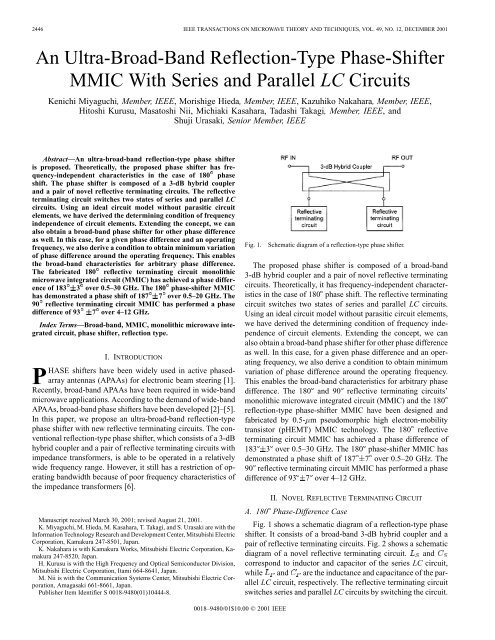
Fig. 1.<br />
Schematic diagram of a <strong>reflection</strong>-<strong>type</strong> <strong>phase</strong> <strong>shifter</strong>.<br />
The proposed <strong>phase</strong> <strong>shifter</strong> is composed of a <strong>broad</strong>-<strong>band</strong><br />
3-dB hybrid coupler and a pair of novel reflective terminating<br />
circuits. Theoretically, it has frequency-independent characteristics<br />
in the case of 180 <strong>phase</strong> shift. The reflective terminating<br />
circuit switches two states of series and parallel LC circuits.<br />
Using an ideal circuit model <strong>with</strong>out parasitic circuit elements,<br />
we have derived the determining condition of frequency independence<br />
of circuit elements. Extending the concept, we can<br />
also obtain a <strong>broad</strong>-<strong>band</strong> <strong>phase</strong> <strong>shifter</strong> for other <strong>phase</strong> difference<br />
as well. In this case, for a given <strong>phase</strong> difference and an operating<br />
frequency, we also derive a condition to obtain minimum<br />
variation of <strong>phase</strong> difference around the operating frequency.<br />
This enables the <strong>broad</strong>-<strong>band</strong> characteristics for arbitrary <strong>phase</strong><br />
difference. The 180 and 90 reflective terminating circuits’<br />
monolithic microwave integrated circuit (<strong>MMIC</strong>) and the 180<br />
<strong>reflection</strong>-<strong>type</strong> <strong>phase</strong>-<strong>shifter</strong> <strong>MMIC</strong> have been designed and<br />
fabricated by 0.5- m pseudomorphic high electron-mobility<br />
transistor (pHEMT) <strong>MMIC</strong> technology. The 180 reflective<br />
terminating circuit <strong>MMIC</strong> has achieved a <strong>phase</strong> difference of<br />
183 3 over 0.5–30 GHz. The 180 <strong>phase</strong>-<strong>shifter</strong> <strong>MMIC</strong> has<br />
demonstrated a <strong>phase</strong> shift of 187 7 over 0.5–20 GHz. The<br />
90 reflective terminating circuit <strong>MMIC</strong> has performed a <strong>phase</strong><br />
difference of 93 7 over 4–12 GHz.<br />
II. NOVEL REFLECTIVE TERMINATING CIRCUIT<br />
A. 180 Phase-Difference Case<br />
Fig. 1 shows a schematic diagram of a <strong>reflection</strong>-<strong>type</strong> <strong>phase</strong><br />
<strong>shifter</strong>. It consists of a <strong>broad</strong>-<strong>band</strong> 3-dB hybrid coupler and a<br />
pair of reflective terminating circuits. Fig. 2 shows a schematic<br />
diagram of a novel reflective terminating circuit. and<br />
correspond to inductor and capacitor of the series LC circuit,<br />
while and are the inductance and capacitance of the parallel<br />
LC circuit, respectively. The reflective terminating circuit<br />
switches series and parallel LC circuits by switching the circuit.<br />
0018–9480/01$10.00 © 2001 IEEE
MIYAGUCHI et al.: ULTRA-BROAD-BAND REFLECTION-TYPE PHASE-SHIFTER <strong>MMIC</strong> WITH SERIES AND PARALLEL LC CIRCUITS 2447<br />
Substituting (7) into (8), we can obtain the following polynomial<br />
equation:<br />
(9)<br />
Fig. 2.<br />
Schematic diagram of a novel reflective terminating circuit.<br />
The coefficients of all terms <strong>with</strong> respect to have to be zero<br />
to satisfy (9) for all . We can then derive the determining condition<br />
as follows:<br />
Reflection coefficients and of series and parallel LC<br />
circuits are given by<br />
(1)<br />
Substituting (10) into (7) leads to<br />
(10)<br />
(11)<br />
where<br />
(2)<br />
As a result, it has been shown that only an 180 <strong>phase</strong> difference<br />
is obtained <strong>with</strong>out frequency dependence by satisfying<br />
the determining condition of (10).<br />
(3)<br />
(4)<br />
In (1)–(4), and are the impedance of series and parallel<br />
LC circuits and and are the <strong>reflection</strong> <strong>phase</strong> of series and<br />
parallel LC circuits, respectively. is the impedance of a 3-dB<br />
hybrid coupler. Using (1) and (2), and can be written as<br />
(5)<br />
B. Non-180 Phase-Difference Case<br />
Next, we derive the condition in the case of non-180 <strong>phase</strong>difference<br />
over a <strong>broad</strong> <strong>band</strong>width. To yield a <strong>broad</strong>-<strong>band</strong><br />
<strong>phase</strong> difference characteristics, it is required to satisfy conditions<br />
as follows :<br />
(12)<br />
(13)<br />
Substituting (7) into (12), we obtain the following equations:<br />
(6)<br />
(14)<br />
The <strong>phase</strong> difference<br />
is defined by the following equation:<br />
(15)<br />
From (7) and (13), we obtain the following equations:<br />
(7)<br />
(16)<br />
In order to obtain <strong>broad</strong>-<strong>band</strong> <strong>phase</strong> difference characteristics,<br />
has to satisfy the following condition for all frequencies:<br />
for all (8)<br />
(17)
2448 IEEE TRANSACTIONS ON MICROWAVE THEORY AND TECHNIQUES, VOL. 49, NO. 12, DECEMBER 2001<br />
To reduce (14)–(17) to solvable forms, we introduce the conditions<br />
as follows:<br />
(18)<br />
(19)<br />
(20)<br />
Equation (18) corresponds to the condition that at is the<br />
<strong>phase</strong> difference between the series circuit as a short<br />
termination and parallel circuit . Equation (19) corresponds<br />
to the condition that at is the <strong>phase</strong> difference between<br />
the series circuit and parallel circuit as<br />
an open termination. The is the center frequency of and<br />
.<br />
We can then reduce (14) and (15) to the following equations:<br />
(21)<br />
Fig. 3.<br />
circuit.<br />
Ideal <strong>phase</strong>-difference characteristics of the reflective terminating<br />
The circuit elements , , , and are then given as<br />
follows:<br />
(30)<br />
(22)<br />
(31)<br />
Equations (21) and (22) can be rewritten as follows:<br />
(32)<br />
(23)<br />
(24)<br />
Finally, we obtain solvable forms of (14) and (15) as follows:<br />
We also reduce (16) and (17) to solvable forms as follows:<br />
Let be the coefficient of (27). From (20) and (27),<br />
and are expressed as follows:<br />
(25)<br />
(26)<br />
(27)<br />
(28)<br />
(29)<br />
(33)<br />
Therefore, the circuit elements have been expressed as functions<br />
of and . Substituting (30)–(33) <strong>with</strong> (7), it is easily<br />
shown that is a function of . The ideal <strong>phase</strong>-difference<br />
characteristics versus normalized frequency are plotted<br />
in Fig. 3. In the case of a 90 <strong>phase</strong> difference, the <strong>phase</strong>-difference<br />
variation is less than 1.17 over to , where and<br />
are and , respectively.<br />
III. DESIGN<br />
A. 180 Reflective-Terminating-Circuit <strong>MMIC</strong><br />
Fig. 4 shows a schematic diagram of the proposed 180 reflective<br />
terminating circuit. It consists of only a few circuit elements<br />
of built-in inductor , built-in capacitor , and a pair of FET1<br />
and FET2. These FETs are used as switching elements.<br />
Fig. 5 shows equivalent circuits of parallel and series LC<br />
states of the 180 reflective terminating circuit, respectively.<br />
and are the on-state resistances of FET1 and FET2,<br />
respectively. and are the off-capacitances of FET1<br />
and FET2, respectively. In parallel LC state operation, FET1<br />
and FET2 are turned on, as shown in Fig. 5(a). By neglecting<br />
and , the circuit can be simplified to a parallel LC<br />
circuit, which corresponds to the parallel resonant circuit of<br />
in Fig. 2. In series LC state operation, FET1 and FET2<br />
are pinched off, as shown in Fig. 5(b). When the admittance of<br />
a series capacitance combination consisting of and is
MIYAGUCHI et al.: ULTRA-BROAD-BAND REFLECTION-TYPE PHASE-SHIFTER <strong>MMIC</strong> WITH SERIES AND PARALLEL LC CIRCUITS 2449<br />
Fig. 6.<br />
Schematic diagram of a proposed 90 reflective terminating circuit.<br />
Fig. 4.<br />
Schematic diagram of proposed 180 reflective terminating circuit.<br />
(a)<br />
(a)<br />
(b)<br />
Fig. 7. Equivalent circuits of parallel and series LC states of 90 reflective<br />
terminating circuit. (a) Parallel LC state. (b) Series LC state.<br />
(b)<br />
Fig. 5. Equivalent circuits of parallel and series LC states of 180 reflective<br />
terminating circuit. (a) Parallel LC state. (b) Series LC state.<br />
small enough to be neglected, the circuit can be simplified to a<br />
series LC circuit, which corresponds to the series resonant circuit<br />
of in Fig. 2. Therefore, Fig. 4 can be identical to<br />
Fig. 2 provided that plays the role of and simultaneously.<br />
From (10), , and must be equal to .We<br />
have the determining condition for the circuit shown in Fig. 4.<br />
When the resonant frequency of the parallel and the series LC<br />
circuits is set to be , the circuit elements of and<br />
are determined uniquely as follows:<br />
(34)<br />
(35)<br />
However, the parallel LC state has a return loss that is determined<br />
by nonzero and . The return-loss increase in<br />
the parallel LC state particularly appears at . Therefore, the<br />
parasitic resistances of FETs place a constraint on the operating<br />
<strong>band</strong>width. has to be optimally determined larger than the<br />
operating <strong>band</strong>width. From (34) and (35), the values of and<br />
are 0.23 nH and 0.09 pF under the assumption of<br />
and<br />
GHz.<br />
B. 90 Reflective Terminating Circuit <strong>MMIC</strong><br />
Fig. 6 shows a schematic diagram of a proposed 90 reflective<br />
terminating circuit. It consists of two inductors, two capacitors,<br />
and their FETs. These FETs are used as switching elements.<br />
Fig. 7 shows equivalent circuits of parallel and series LC<br />
states of the 90 reflective terminating circuit, respectively.<br />
and are the on-state resistances of FET1,<br />
FET2, and FET3, respectively. and are the<br />
off-capacitances of FET1, FET2, and FET3, respectively. In<br />
parallel LC state operation, FET2 is pinched off and FET1 and<br />
FET3 are turned on, as shown in Fig. 7(a). In the condition<br />
that and can be neglected, the circuit<br />
can be simplified to a parallel LC circuit, which corresponds<br />
to the parallel resonant circuit of in Fig. 2. In series<br />
LC state operation, FET1 and FET3 are pinched off and<br />
FET2 is turned on, as shown in Fig. 7(b). In the condition<br />
that and can be neglected,<br />
the circuit can be simplified to a series LC circuit, which<br />
corresponds to the series resonant circuit of in Fig. 2.<br />
The FET size was determined so as to equalize the return loss<br />
of the series and parallel LC states due to small<br />
and . From (30)–(33), the values of and
2450 IEEE TRANSACTIONS ON MICROWAVE THEORY AND TECHNIQUES, VOL. 49, NO. 12, DECEMBER 2001<br />
Fig. 11.<br />
180 <strong>phase</strong>-<strong>shifter</strong> <strong>MMIC</strong>.<br />
Fig. 8.<br />
Fabricated 180 reflective terminating circuit <strong>MMIC</strong>.<br />
Fig. 12.<br />
Phase-shift performance of the 180 <strong>phase</strong>-<strong>shifter</strong> <strong>MMIC</strong>.<br />
Fig. 9. Phase-difference performance of the 180 reflective terminating circuit<br />
<strong>MMIC</strong>.<br />
(a)<br />
Fig. 10.<br />
<strong>MMIC</strong>.<br />
Return-loss performance of the 180 reflective terminating circuit<br />
are 0.68 nH, 3.26 pF, 2.19 nH, and 0.073 pF, respectively, under<br />
the assumption of and GHz. and<br />
are GHz and GHz, respectively.<br />
IV. MEASURED RESULTS<br />
A. 180 Reflective Terminating Circuit and Phase-Shifter<br />
<strong>MMIC</strong><br />
Fig. 8 depicts a photograph of a fabricated 180 reflective<br />
terminating circuit <strong>MMIC</strong>. The integrated circuit (IC) has been<br />
fabricated by using 0.5- m pHEMT technology. To equalize<br />
the return loss between parallel and series LC states, a resistor<br />
(b)<br />
Fig. 13. Insertion- and return-loss performance of the 180 <strong>phase</strong>-<strong>shifter</strong><br />
<strong>MMIC</strong> (a) Parallel LC state. (b) Series LC state.<br />
is incorporated between source and drain terminals of FET1.<br />
That resistor has a negligible effect on <strong>phase</strong> difference and<br />
impedance of the circuit. Fig. 9 shows the simulated and<br />
measured <strong>phase</strong>-difference characteristics of the 180 reflective<br />
terminating circuit <strong>MMIC</strong>. Fig. 10 shows the return-loss
MIYAGUCHI et al.: ULTRA-BROAD-BAND REFLECTION-TYPE PHASE-SHIFTER <strong>MMIC</strong> WITH SERIES AND PARALLEL LC CIRCUITS 2451<br />
Fig. 14.<br />
Fabricated 90 reflective terminating circuit <strong>MMIC</strong>.<br />
Fig. 16.<br />
<strong>MMIC</strong>.<br />
Return-loss performance of the 90 reflective terminating circuit<br />
1.95 0.7 dB at the same frequency range. The difference between<br />
the measured and simulated <strong>phase</strong> difference are mainly<br />
caused by differences between the measured and simulated<br />
FET characteristics used in it.<br />
Fig. 15.<br />
<strong>MMIC</strong>.<br />
Phase-difference performance of the 90 reflective terminating circuit<br />
characteristics. Both of the measured and simulated results are<br />
in good agreement. The measured <strong>phase</strong> difference is 183 3<br />
over 0.5–30 GHz, and the measured return loss is 2.3 0.4 dB<br />
over 0.5–20 GHz.<br />
Fig. 11 presents an <strong>ultra</strong>-<strong>broad</strong>-<strong>band</strong> 180 <strong>reflection</strong>-<strong>type</strong><br />
<strong>phase</strong>-<strong>shifter</strong> <strong>MMIC</strong> fabricated by the same process. It consists<br />
of a 3-dB Lange coupler and a pair of 180 reflective<br />
terminating circuits. Fig. 12 shows the measured and simulated<br />
<strong>phase</strong>-shift characteristics of the <strong>phase</strong>-<strong>shifter</strong> <strong>MMIC</strong>. Fig. 13<br />
shows the measured and simulated loss characteristics. The<br />
measured <strong>phase</strong> shift is 187 7 over 0.5–20 GHz. The<br />
measured insertion loss is 3.7 0.6 dB over 6–20 GHz and<br />
the measured insertion-loss error between parallel and series<br />
LC states is less than 1 dB at the same frequency range. The<br />
difference between the measured and simulated <strong>phase</strong> shift is<br />
mainly due to differences between the model parameter and<br />
measured data of a 3-dB Lange coupler used in it.<br />
B. 90 Reflective Terminating Circuit <strong>MMIC</strong><br />
Fig. 14 depicts a photograph of a 90 reflective terminating<br />
circuit <strong>MMIC</strong> fabricated by the same process. Fig. 15 shows<br />
the simulated and measured <strong>phase</strong>-difference characteristics<br />
of the 90 reflective terminating circuit <strong>MMIC</strong>. Fig. 16 shows<br />
the return-loss characteristics. The measured <strong>phase</strong> difference<br />
is 93 7 over 4–12 GHz, and the measured return loss is<br />
V. CONCLUSIONS<br />
We have presented an <strong>ultra</strong>-<strong>broad</strong>-<strong>band</strong> <strong>reflection</strong>-<strong>type</strong> <strong>phase</strong><br />
<strong>shifter</strong>, which is composed of a <strong>broad</strong>-<strong>band</strong> 3-dB hybrid coupler<br />
and a pair of novel reflective terminating circuits. Theoretically,<br />
the proposed <strong>phase</strong> <strong>shifter</strong> has frequency-independent<br />
characteristics in the case of a 180 <strong>phase</strong> shift. The reflective<br />
terminating circuit switches two states of series and parallel LC<br />
circuits. Using an ideal circuit model <strong>with</strong>out parasitic circuit elements,<br />
we have derived the determining condition of circuit elements<br />
for frequency independence. Extending the concept, we<br />
can also obtain a <strong>broad</strong>-<strong>band</strong> <strong>phase</strong> <strong>shifter</strong> for other <strong>phase</strong> differences<br />
as well. For a given <strong>phase</strong> difference and an operating<br />
frequency, we also have derived a condition to obtain minimum<br />
variation of <strong>phase</strong> difference around the operating frequency.<br />
The fabricated 180 reflective terminating circuit <strong>MMIC</strong> has<br />
achieved a <strong>phase</strong> difference of 183 3 over 0.5–30 GHz. The<br />
fabricated 180 <strong>phase</strong>-<strong>shifter</strong> <strong>MMIC</strong> utilizing the reflective terminating<br />
circuits has successfully demonstrated a <strong>phase</strong> shift<br />
of 187 7 over 0.5–20 GHz. The fabricated 90 reflective terminating<br />
circuit <strong>MMIC</strong> has performed a <strong>phase</strong> difference of<br />
93 7 over 4–12 GHz.<br />
REFERENCES<br />
[1] R. V. Garver, “Broad-<strong>band</strong> diode <strong>phase</strong> <strong>shifter</strong>s,” IEEE Trans. Microwave<br />
Theory Tech., vol. MTT-20, pp. 314–323, May 1972.<br />
[2] J. P. Starski, “Optimization of the matching network for a hybrid coupler<br />
<strong>phase</strong> <strong>shifter</strong>,” IEEE Trans. Microwave Theory Tech., vol. MTT-25, pp.<br />
662–666, Aug. 1977.<br />
[3] M. Schindler, Y. Ayasli, A. Morris, and L. Hanes, “Monolithic 6–18 GHz<br />
3-bit <strong>phase</strong> <strong>shifter</strong>,” in IEEE GaAs IC Symp. Dig., 1985, pp. 129–132.<br />
[4] D. C. Boire, J. E. Dejenford, and M. Cohn, “A 4.5 to 18 GHz <strong>phase</strong><br />
<strong>shifter</strong>,” in IEEE MTT-S Int. Microwave Symp. Dig., 1985, pp. 601–604.<br />
[5] D. C. Boire, G. St. Onge, C. Barratt, G. B. Norris, and A. Moysenko,<br />
“4 : 1 <strong>band</strong>width digital five bit <strong>MMIC</strong> <strong>phase</strong> <strong>shifter</strong>s,” in IEEE<br />
Microwave Millimeter-Wave Monolithic Circuits Symp. Dig., 1989, pp.<br />
69–73.<br />
[6] H. A. Atwater, “Reflection coefficient transformations for <strong>phase</strong>-shift<br />
circuits,” IEEE Trans. Microwave Theory Tech., vol. MTT-28, pp.<br />
563–567, June 1980.
2452 IEEE TRANSACTIONS ON MICROWAVE THEORY AND TECHNIQUES, VOL. 49, NO. 12, DECEMBER 2001<br />
(IEICE), Japan.<br />
Kenichi Miyaguchi (M’00) received the B.E. and<br />
M.E. degrees in electrical and electronic engineering<br />
from Kyoto University, Kyoto, Japan, in 1997 and<br />
1999, respectively.<br />
In 1999, he joined the Information Technology Research<br />
and Development Center, Mitsubishi Electric<br />
Corporation, Kamakura, Japan, where he has been<br />
engaged in research and development of microwave<br />
control circuits and <strong>MMIC</strong>s.<br />
Mr. Miyaguchi is a member of the Institute of Electronics,<br />
Information and Communication Engineers<br />
Japan.<br />
Masatoshi Nii received the B.E. and M.E. degrees in<br />
electronic and electrical engineering from Fukuoka<br />
University, Fukuoka, Japan, in 1989 and 1991, respectively.<br />
In 1991, he joined the Communication Systems<br />
Center, Mitsubishi Electric Corporation, Amagasaki,<br />
Japan, where he has been engaged in the development<br />
of microwave modules, microwave circuits,<br />
and <strong>MMIC</strong>s.<br />
Mr. Nii is a member of the Institute of Electronics,<br />
Information and Communication Engineers (IEICE),<br />
Morishige Hieda (M’94) was born in Toyoma,<br />
Japan. He received the B.E. and M.E. degrees in<br />
electronic engineering from Tohoku University,<br />
Sendai, Japan, in 1988 and 1990, respectively.<br />
In 1990, he joined the Information Technology<br />
Research and Development Center, Mitsubishi<br />
Electric Corporation, Kamakura, Japan, where he<br />
has been engaged in research and development of<br />
millimeter-wave mixers, microwave control circuits,<br />
and <strong>MMIC</strong>s.<br />
Mr. Hieda is a member of the Institute of Electronics,<br />
Information and Communication Engineers (IEICE), Japan.<br />
Kazuhiko Nakahara (M’01) received the B.S. and<br />
Ph.D. degrees in electronics from Hokkaido University,<br />
Sapporo, Japan, in 1983 and 2001, respectively.<br />
In 1983, he joined the Mitsubishi Electric Corporation,<br />
Kamakura, Japan, where he was engaged<br />
in research and development of microwave ICs and<br />
<strong>MMIC</strong>s. He is currently <strong>with</strong> Kamakura Works,<br />
Mitsubishi Electric Corporation, Kamakura, Japan.<br />
Dr. Nakahara is a member of the Institute of Electronics,<br />
Information and Communication Engineers<br />
(IEICE), Japan.<br />
Hitoshi Kurusu received the B.E. and M.E. degrees<br />
in electrical and electronic engineering from Kyoto<br />
University, Kyoto, Japan, in 1994 and 1996, respectively.<br />
In 1996, he joined the High Frequency and Optical<br />
Semiconductor Division, Mitsubishi Electric Corporation,<br />
Itami, Japan, where he has been engaged in<br />
research and development of microwave control circuits<br />
and <strong>MMIC</strong>s.<br />
Michiaki Kasahara received the B.E. degree<br />
in electrical engineering from the University of<br />
Electro-Communications, Tokyo, Japan, in 1985.<br />
In 1985, he joined the Information Technology Research<br />
and Development Center, Mitsubishi Electric<br />
Corporation, Kamakura, Japan, where he has been<br />
engaged in development of RF equipment for radar<br />
systems<br />
Mr. Kasahara is a member of the Institute of Electronics,<br />
Information and Communication Engineers<br />
(IEICE), Japan.<br />
Tadashi Takagi (M’92) received the B.S. degree<br />
in physics from the Tokyo Institute of Technology,<br />
Tokyo, Japan, in 1973, and Ph.D. degree in electronic<br />
engineering from Shizuoka University, Sizuoka,<br />
Japan, in 1995.<br />
In 1973, he joined the Mitsubishi Electric<br />
Corporation, Kamakura, Japan, where he was<br />
engaged in research and development of microwave<br />
circuits and <strong>MMIC</strong>s and solid-state power amplifiers<br />
(SSPAs). He is currently the Project Manager of<br />
the Microwave Prototyping Project Group, Information<br />
Technology Research and Development Center, Mitsubishi Electric<br />
Corporation.<br />
Dr. Takagi is a member of the Institute of Electronics, Information and Communication<br />
Engineers (IEICE), Japan.<br />
Shuji Urasaki (M’82–SM’94) received the B.S.,<br />
M.S., and Ph.D. degrees in electronic engineering<br />
from Hokkaido University, Sapporo, Japan, in 1967,<br />
1969, and 1985, respectively.<br />
In 1969, he joined the Mitsubishi Electric<br />
Corporation, Tokyo, Japan, where he was involved<br />
<strong>with</strong> antennas for public communications, satellite<br />
communications, and radar systems. He is currently<br />
the General Manager of the Electro-Optics and<br />
Microwave Systems Laboratory, Information<br />
Technology Research and Development Center,<br />
Mitsubishi Electric Corporation, Kamakura, Japan.<br />
Dr. Urasaki is a member of the Institute of Electronics, Information and Communication<br />
Engineers (IEICE), Japan.


