Electrical Machine - IES Academy
Electrical Machine - IES Academy
Electrical Machine - IES Academy

Create successful ePaper yourself
Turn your PDF publications into a flip-book with our unique Google optimized e-Paper software.
India’s No. 1<br />
<strong>IES</strong> <strong>Academy</strong><br />
Transformer<br />
Chapter-1<br />
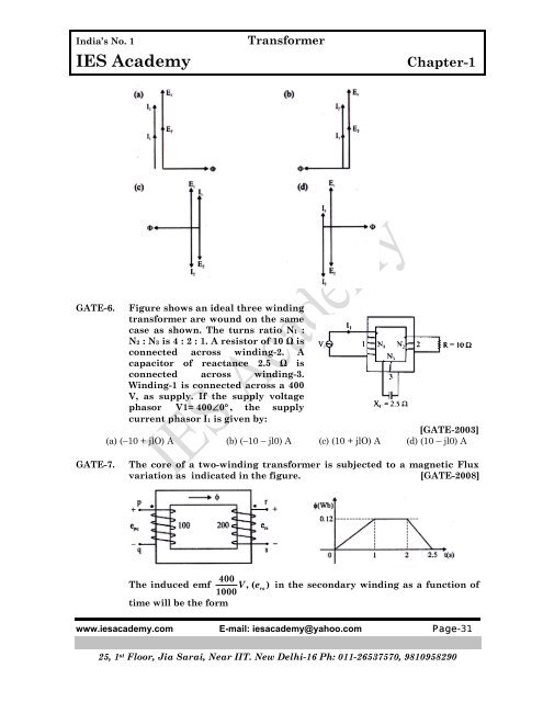
GATE-6. Figure shows an ideal three winding<br />
transformer are wound on the same<br />
case as shown. The turns ratio N1 :<br />
N2 : N3 is 4 : 2 : 1. A resistor of 10 Ω is<br />
connected across winding-2. A<br />
capacitor of reactance 2.5 Ω is<br />
connected across winding-3.<br />
Winding-1 is connected across a 400<br />
V, as supply. If the supply voltage<br />
phasor V1= 400∠ 0° , the supply<br />
current phasor I1 is given by:<br />
[GATE-2003]<br />
(a) (–10 + jlO) A (b) (–10 – jl0) A (c) (10 + jlO) A (d) (10 – jl0) A<br />
GATE-7.<br />
The core of a two-winding transformer is subjected to a magnetic Flux<br />
variation as indicated in the figure.<br />
[GATE-2008]<br />
The induced emf 400 V,( e<br />
rs<br />
) in the secondary winding as a function of<br />
1000<br />
time will be the form<br />
www.iesacademy.com E-mail: iesacademy@yahoo.com Page-31<br />
25, 1 st Floor, Jia Sarai, Near IIT. New Delhi-16 Ph: 011-26537570, 9810958290