


Create successful ePaper yourself
Turn your PDF publications into a flip-book with our unique Google optimized e-Paper software.
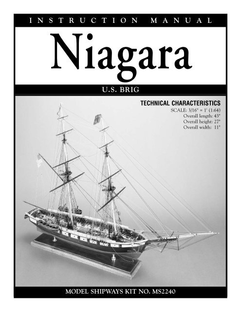
I N S T R U C T I O N M A N U A L<br />
Niagara<br />
U.S. BRIG<br />
MODEL SHIPWAYS KIT NO. MS2240<br />
TECHNICAL CHARACTERISTICS<br />
SCALE: 3/16" = 1' (1:64)<br />
Overall length: 43"<br />
Overall height: 27"<br />
Overall width: 11"
HISTOR HISTORY<br />
The original Niagara was Commodore Oliver Hazard Perry's second flagship during the Battle of Lake Erie on<br />
September 10, 1813. His victory over the British secured the Northwest Territory, opened supply lines, and lifted<br />
the nation's morale.<br />
Six ships in Perry's fleet of nine, including Niagara, were built in Erie, Pennsylvania. To accomplish the task,<br />
shipwrights, block makers, caulkers, boatbuilders, and laborers were recruited from Pittsburgh, Philadelphia,<br />
and elsewhere. Material was brought in from all over the country.<br />
The Navy assigned ship master Daniel Dobbins of Erie to direct construction until experienced builders arrived.<br />
In February 1813, Noah Brown, a New York shipbuilder, was hired to complete the construction. He also<br />
designed two of the four schooners and the brigs, Niagara and Lawrence.<br />
On March 27, 1813, Commodore Perry took command of the American naval forces at Lake Erie. When the<br />
famous battle began six months later, Perry was aboard Lawrence, his flagship. He was soon engaged in a tremendous<br />
battle with the main strength of the British line. However, for more than two hours Commander Jessie<br />
Elliott kept Niagara well removed from the action, content to lob shots at his adversary with two 12-pound long<br />
guns. After two-and-three-quarter hours of murderous gunfire, Lawrence was "one confused heap of horrid<br />
ruins." Perry gave up his flagship and was rowed to Niagara where he continued to attack. Two-and-a-half hours<br />
later, Perry returned to the shattered Lawrence, went to his cabin, and penned a quick message to General<br />
Harrison: "We have met the enemy and they are ours — Two Ships, two <strong>Brig</strong>s, one Schooner and one Sloop."<br />
After the War of 1812, Niagara served as a station ship in Erie until 1820. Then she was scuttled in Misery Bay.<br />
For the centennial of the battle, Erie citizens raised the hulk and rebuilt the ship. Another restoration began in<br />
1931, but the Depression slowed progress. The hull was completed in 1943 and masts installed in 1963. By 1988,<br />
Niagara was again deteriorating. The Pennsylvania Historical and Museum Commission hired Melbourne<br />
Smith, a world-famous naval architect, to redesign the entire ship and direct construction. Niagara was<br />
relaunched on the battle's 175th anniversary. Only a few original timbers remain in the hull, and these are used<br />
in non-structural locations. The reconstruction was completed in 1990.<br />
The new Niagara hull length is 123 feet with a 32 foot beam. Draft at the stern is 10 feet 3 inches, and she displaces<br />
297 tons. The tons burthen (old measure) is 492 60/95 tons. In 1813, the ship carried 155 officers and men,<br />
and was armed with eighteen 32-pounder carronades and two long 12-pounders. Today, 40 professionals and<br />
volunteers man Niagara and four replica carronades comprise her ordnance.<br />
Niagara is operated by the Pennsylvania Historical and Museum Commission, with the assistance of the<br />
Flagship Niagara League, a non-profit associate group. The ship sails daily and serves as the Commonwealth's<br />
goodwill ambassador. She is the centerpiece of a new maritime museum in Erie, Pennsylvania.<br />
For more history on Niagara and the War of 1812, refer to the bibliography.<br />
2<br />
Photo Courtesy of<br />
Melbourne Smith
TABLE ABLE OF CONTENTS<br />
Brief History 2<br />
Introduction and Credits 4<br />
Before You Begin 5<br />
Tools Needed To Start Construction 5<br />
How to Work With Plans And Parts 6,7<br />
Painting and Staining The Model 8,9<br />
Stage 1: Framing the Plank-on-Bulkhead Hull 10<br />
1. Bending Wood 10<br />
2. Center Keel Assembly 10<br />
3. Installing the Keel, Stem, and Sternpost 10<br />
4. Cutting the Rabbet 10<br />
5. Installing the Bulkheads 10,11<br />
6. Installing the Stern Blocks<br />
and Transom Framing 12<br />
7. Installing the Bow Filler Blocks 12<br />
8. Covering the Mast Slots 12<br />
9. Installing the Waterway and Planksheer 12<br />
10. Installing the Knightheads<br />
and Forward Timberheads 13<br />
11. Installing the Main Rail and Chock Rail 13<br />
12. Framing Around the Gunports and Sweep Ports 13<br />
Stage 2: Planking the Plank-on-Bulkhead Hull 14<br />
1. Getting Started 14<br />
2. Planking Battens and Belts 14<br />
3. Planking Butts 15<br />
4. Spiling 15<br />
5. Fastening the Planks 15<br />
6. Outer Hull Planking 16,17<br />
7. Ceiling (Inboard) Planking 18<br />
8. Deck Planking 18<br />
Stage 3: Completing the Basic Hull Stucture 18<br />
Stage 4: Mounting the Hull 19<br />
1. Mounting Board with Two Pedestals 19<br />
2. Launching Ways 19<br />
Stage 5: Adding Hull Details 19<br />
1. Locating Deck Fittings and Structures 19<br />
2. Deck Structures 19<br />
3. Hatches, and Grating 20<br />
4. Boarding Ladders 20<br />
5. Galley Stack 20<br />
6. Capstan 20<br />
7. Fife Rails and Riding Bitts 20<br />
8. Pin Rails 20<br />
9. Bilge Pumps 20<br />
10. Scuppers 20<br />
11. Catheads and Anchors 21<br />
12. Mooring Cleats 21<br />
13. Hawse Pipes 21<br />
3<br />
14. Eyebolts and Cleats 21<br />
15. Cannons 21<br />
16. Rudder and Tiller 22<br />
17. Boat Davits and Slides 22<br />
18. Ship's Boats 22,23<br />
19. Ship's Name 23<br />
20. Hammock Rails and Stanchions 23<br />
21. Channels 23<br />
22. Sweeps 23<br />
Stage 6: Mast and Spar Construction 24<br />
1. Shaping and Tapering Masts and Spars 24<br />
2. Building and Installing the Masts 24,25<br />
3. Building and Installing the Bowsprit,<br />
Jibboom, Flying Jibboom, Spritsail Yard,<br />
and Dolphin Striker 25,26<br />
4. Building the Yards 26<br />
5. Building the Spanker Gaff and Boom 26<br />
Stage 7: General Rigging and Sailmaking 27,28<br />
1. Rigging Options 28<br />
2. Rigging Plans 28<br />
3. Rigging Line and Block Sizes 28<br />
4. Treating the Lines 28<br />
5. Belaying Pins, Cleats and Their Lines 29<br />
6. Rigging Tools 29<br />
7. Blocks, Hearts, Bullseyes, and Deadeyes 29<br />
8. Sailmaking 29,30<br />
9. Rigging the Model with No Sails or Furled Sails 31<br />
Stage 8: Installing Standing Rigging 31<br />
1. Shrouds 31<br />
2. Backstays 31,32<br />
3. Fore and Aft Stays 32,33<br />
4. Bowsprit Rigging 33<br />
5. Footropes, Fixed Lifts, and Cranelines 34<br />
Stage 9: Installing Sails and Running Rigging 34<br />
1. Fore Staysails (Head Sails) 34,35<br />
2. Main Staysails 35<br />
3. Spanker 35<br />
4. Fore and Main Course Yards 36<br />
5. Fore and Main Topsail Yards 36<br />
6. Fore and Main Topgallant and Royal Yards 37<br />
7. Spritsail Yard 37<br />
8. Miscellaneous Rigging 37<br />
Final Touches 37<br />
Bibliography 38<br />
Scale Conversion Table 38<br />
Rigging Line Diameters 38<br />
Modeler's Log 39,40
Instruction Manual<br />
U.S. <strong>Brig</strong><br />
Niagara<br />
1813 –1990<br />
Plans and Instructions<br />
by Ben Lankford<br />
Model by William Hitchcock<br />
Model Shipways developed the Niagara kit in 1996. Plans are based on the 1990 reconstruction drawings,<br />
research sketches, and specifications prepared and supplied by the designer, naval architect Melbourne<br />
Smith, International Historical Watercraft Society, Annapolis, Maryland. Many as-built features deviating<br />
from the plans are incorporated. These are based on visits to the brig and photographs. In addition to providing<br />
invaluable design information, Smith reviewed Model Shipways' plans for accuracy.<br />
Modern features, such as engines and a housing over the exhaust system, are not included to maintain<br />
Niagara's 1813 configuration.<br />
Photo Courtesy<br />
of Melbourne Smith<br />
© 1998<br />
Model Shipways, A Division of Model Expo, Inc.<br />
Hollywood, FL 33020<br />
4
Before You Begin<br />
Niagara is a beautiful, interesting ship and makes a splendid model. Assembling the plank-on-bulkhead hull develops<br />
an understanding of how real ships are built, while laser-cut parts assure an accurate shape. The kit contains more than<br />
150 laser-cut wood parts.<br />
Although britannia, brass, and wood fittings facilitate construction, many require final finishing prior to installation.<br />
This is especially true for the britannia castings and is discussed later.<br />
Take your time building this model. It has a fair amount of detail and small parts. Furthermore, the rigging is fairly complicated.<br />
Complete one stage before moving to the next. When things go awry, consider doing them over. A second attempt<br />
usually surpasses the first. Practice does make perfect.<br />
Tools Needed To Start Construction<br />
The following items are recommended. Those who have modeled before may have their favorites.<br />
A. Knives and Saws<br />
1. <strong>Hobby</strong> knife<br />
2. #11 blades<br />
3. Razor saw or jeweler’s saw<br />
B. Files<br />
1. Set of needle files<br />
C. Clamps<br />
1. A few small C-clamps<br />
2. Wooden spring-type clothes pins<br />
(craft shops have small versions)<br />
3. #16 and #33 rubber bands<br />
D. Carving Tools<br />
Small woodcarving set, or individual<br />
gouges and chisels for carving keel<br />
rabbets, bow and stern filler blocks,<br />
ship's boats, and tapering the stem<br />
and rudder.<br />
E. Sharpening Stone<br />
Keeps tools razor sharp.<br />
F. Boring Tools<br />
1. #60 to #80 miniature bits<br />
2. 1/16”, 3/32”, and 1/8” bits<br />
3. Pin vise<br />
G. Miscellaneous<br />
1. Tack hammer<br />
2. Tweezers (a few)<br />
3. Small, fine pointed scissors<br />
4. Miniature pliers<br />
a. round nose<br />
b. flat nose<br />
5. Small bench vise<br />
6. Soldering iron or torch<br />
a. solder<br />
b. flux<br />
7. Sewing thread for seizing<br />
(other rigging in kit)<br />
a. black<br />
b. tan<br />
8. Beeswax block<br />
(for treating rigging lines)<br />
9. 1/2” or 3/4” wide masking tape<br />
10. Wire cutters (for cutting fine wire<br />
and strip metal)<br />
H. Sandpaper<br />
1. Fine and medium grit<br />
garnet or #100 to #200<br />
aluminum oxide<br />
2. #400 wet-or-dry sandpaper<br />
I. Sail cloth<br />
Light weave cotton or linen cloth for<br />
sails. Model Expo sells a suitable<br />
cotton cloth.<br />
J. Finishing<br />
1. Paintbrushes<br />
a. Fine point for details<br />
b. 1/4” to 1/2” flat square for hull<br />
K. Supplies<br />
1. Paints<br />
2. Primer<br />
3. Stains and varnish<br />
4. White (polyvinyl acetate or PVA) or<br />
woodworker’s glue (aliphatic resin)<br />
5. Cyanoacrylates (generic name is<br />
Super Glue)<br />
6. Five-minute epoxy<br />
7. Wood filler<br />
5<br />
BELFRY AT BOW<br />
Note: White or woodworker’s glue in yellow<br />
or tan will suffice for most of the model.<br />
Five-minute epoxy provides extra strength<br />
for affixing fittings. Cyanoacrylates, such as<br />
Jet, Flash, or Zap, produce quick adhesion.<br />
For most applications, the medium viscosity,<br />
gap-filling variety is best. The thin type is<br />
recommended for filling a narrow crack and<br />
tacking bulkheads to the keel or planking to<br />
the bulkheads.
How To Work With Plans And Parts<br />
Before starting the model, carefully<br />
examine the kit and study the plans.<br />
First, determine if all the listed parts are<br />
present. Handling them will produce a<br />
better understanding of the kit's requirements.<br />
Try to visualize how every piece<br />
will look on the model. Also, determine<br />
ahead of time what must be done first.<br />
The instructions will help, but a thorough<br />
knowledge of the plans at the outset<br />
is essential.<br />
To avoid losing small fittings and hardware,<br />
sort them into labeled boxes or<br />
compartments. These should have lids to<br />
keep out dirt.<br />
1. The Plans<br />
Six sheets are provided:<br />
1. Laser-Cut Wood Patterns<br />
2. Plank-on-Bulkhead Hull<br />
Construction<br />
3. Hull Plan and Profiles<br />
4. Hull and Spar Details<br />
5. Rigging Profile<br />
6. Rigging Sections and Details<br />
Sketches throughout the manual illustrate<br />
various construction techniques.<br />
The Niagara kit is manufactured to a<br />
scale of 3/16" = 1'0" (1:64). Each plan<br />
sheet is drawn to that scale, except areas<br />
enlarged to show detail. Most dimensions<br />
can be lifted directly off the plans<br />
by using draftsman dividers or a "tick"<br />
strip (piece of paper such as an adding<br />
machine roll). Lay the paper strip over<br />
the plan, carefully mark the item's<br />
length with a sharp pencil, then transfer<br />
the marks to the wood.<br />
A 3/16" architect's or 1:64 metric scale is a<br />
handy tool. Measuring and cutting parts<br />
using the scale gives a better feel for real<br />
sizes. Because these are modelbuilders'<br />
plans, actual measurements were converted<br />
to the nearest 1/64". For example,<br />
a 7/64" block is 7" on the real ship.<br />
Measurements on the plans are in inches,<br />
but Sheet 3 contains a conversion table<br />
giving equivalent real ship sizes in decimals<br />
and millimeters.<br />
2. Making Allowances<br />
Along the Way<br />
Try to be exact when following the plans,<br />
but use common sense. Adjustments<br />
may be necessary to compensate for<br />
small differences in how your model is<br />
shaping up; perhaps one mast has too<br />
much rake (angle to the deck). Lines<br />
should not drape over fittings or conflict<br />
with other lines when belayed (secured).<br />
If necessary, move a belaying point or<br />
fairlead. Put yourself on the ship, imagine<br />
performing the task, and use logic.<br />
3. Understanding Hull Lines<br />
Beginners may not be familiar with hull<br />
lines. Buttock lines are vertical longitudinal<br />
planes cut through the hull. Waterlines<br />
are horizontal planes, and sections are<br />
transverse vertical planes. Diagonals are<br />
diagonal planes cut through the hull.<br />
These lines define the hull's shape and<br />
are used by the draftsman to fair it<br />
(create even curves).<br />
A complete set of hull lines is not needed<br />
for this model, because laser-cut bulkheads<br />
and center keel define the hull.<br />
Sheet 2 shows the bulkheads. They are<br />
similar to a ship's body plan or sections,<br />
and illustrate how the hull curves from<br />
top to bottom.<br />
VIEW AT DOCKSIDE, ERIE, PA.<br />
6<br />
4. Using Basswood Lumber<br />
Basswood comes in 1/32", 3/64", 1/16",<br />
3/32", 1/8", 5/32", 3/16", 1/4", and 1/2"<br />
thick sheets and strips. Strip widths are<br />
in the same increments, while sheets<br />
may be 1", 2", 3", or 4" wide.<br />
Note: Model Shipways occasionally substitutes<br />
lime (Tilia vulgaris), a European<br />
wood, for basswood (Tilia americana). Both<br />
have a fine, uniform texture and straight<br />
grain. Lime, however, has superior steambending<br />
qualities. It is often called basswood<br />
in Europe. Based on Niagara's<br />
3/16" = 1'0" scale, 1/64" equals 1" on the<br />
real ship, 1/32" is to 2", and so on.<br />
Generally, basswood strips or sheets can<br />
be used as is. Occasionally, a strip must be<br />
thinner than the supplied size. To maintain<br />
scale, sand the strip to the required<br />
thickness with a sanding block before<br />
making the part.<br />
Another way to reduce stock is with a<br />
hobby sanding thickness planer (sold<br />
commercially). Those who don't own one<br />
can chuck a sanding drum into their drill<br />
press, clamp a block alongside the drum<br />
to act as a fence, then insert the strip<br />
between the drum and block. This<br />
makeshift tool works quite well.
Sorting the wood in the kit by thickness<br />
saves time. After selecting and cutting<br />
what is needed, return the remaining<br />
stock to the proper thickness pile. Don't<br />
worry about using a piece for one item<br />
that was intended for another. Model<br />
Shipways supplies enough extra wood to<br />
complete the model before running out.<br />
5. Britannia Metal Fittings<br />
Although most parts are wood, the kit<br />
contains a small number of britannia<br />
fittings. Before painting them, remove<br />
any mold joint flash with a #11 hobby<br />
blade, then file smooth or sand with<br />
fine sandpaper. Clean parts in dishwashing<br />
liquid and warm water to<br />
remove traces of mold release agent<br />
and any body oils your fingers have<br />
deposited. Rinse thoroughly and allow<br />
to dry completely before applying primer.<br />
6. Soldering and Working<br />
with Brass<br />
Niagara doesn't require a great deal of<br />
soldering. However, here are a few tips:<br />
Cut brass sheet and strips with a small pair<br />
of tin snips or heavy scissors. Heavier<br />
brass requires a jeweler's saw. After cutting,<br />
smooth the edges with needle files<br />
followed by wet-or-dry fine sandpaper<br />
used dry. Cutting slivers from brass sheet<br />
curls and bends it sideways. To straighten,<br />
grip the ends with a pair of small pliers<br />
and pull in opposite directions. Thin brass<br />
sheets can be scored with a utility knife<br />
and metal straightedge, then snapped off.<br />
Use two or three light passes, cutting<br />
against a maple chopping block, birch<br />
board, or glass backing.<br />
Drilling holes in brass with a pin vise is<br />
a slow process. The solution is to mount<br />
a handpiece for flex-shaft machines in a<br />
hobby drill press. Several companies<br />
manufacturer this tool and it is worth<br />
the cost. When working with brass, use<br />
a 1/4" or thicker piece of maple or birch<br />
for backing. (Avoid softwoods, as these<br />
flare the exit hole.) To prevent the bit<br />
from wandering, mark the spot with a<br />
small center punch. Lubricate the bit<br />
with light oil and drill slowly to avoid<br />
breakage. The brass will become hot, so<br />
clamp the pieces to the drill press table<br />
or hold them down with a wooden<br />
stick. Use a speed reducer to keep rpms<br />
under 2,000; otherwise, excessive heat<br />
buildup will break a small bit.<br />
LOOKING FORWARD<br />
Solder: Until recently, modelers used<br />
pure silver solder to avoid the corrosive<br />
qualities of lead in soft solder. Today,<br />
many solders are lead free. They're composed<br />
of tin and antimony, are strong,<br />
and melt at less than 450º F. Some<br />
brands are mixed with 3% or 4% silver,<br />
but still melt easily. Consequently, no<br />
reason exists to use pure silver solder<br />
(melts at 1300º F).<br />
Flux: Purchase pure solder and buy flux<br />
separately for additional control. Paste<br />
fluxes apply more precisely than liquids,<br />
which run to all the wrong places.<br />
Soldering: The key to soldering is keeping<br />
the brass clean. Use a solvent, lightly<br />
sand, or both. Once the parts are cleaned,<br />
don't touch them. Your fingers will leave<br />
greasy spots. Soldering is easy if your<br />
CAPSTAN AND SKYLIGHTS<br />
7<br />
work is set up properly. First, immobilize<br />
the parts in a fixture or other holding<br />
device, then add just enough flux to the<br />
joint to do the job. Remember, solder<br />
flows where flux is applied.<br />
Next, cut a small piece of solder and lay<br />
it on the joint before heating.<br />
Experiment with various sizes to learn<br />
how much solder it takes to just fill a<br />
joint. The joint should look like the real<br />
thing, not a glob of fillet. Heat the joint<br />
with a small torch or pencil soldering<br />
iron. This sequence is important. The<br />
larger the parts, the longer it takes to<br />
heat the brass and melt the solder.<br />
Remove excess solder with needle files.
Painting And Staining The Model<br />
Beginning with directions on applying<br />
finishes may seem strange, but it isn't.<br />
Much time and effort can be saved and<br />
more professional results obtained if the<br />
finishing process is carried out during<br />
construction. Paint small parts, masts,<br />
and spars before they are installed on<br />
the model. The painting sequence must<br />
be well thought out; otherwise, assembly<br />
difficulties can arise. For example,<br />
painting a cabin or hatch coaming is<br />
easier if it isn't glued to the deck. Store<br />
parts in covered containers until they<br />
are ready to be installed. Proper timing<br />
when applying finishes or using masking<br />
tape to define painted edges should<br />
eliminate unsightly glue marks and<br />
splotchy, stained surfaces. Take advantage<br />
of these general suggestions:<br />
1. Preliminaries<br />
Sanding and Cleaning: Rub down external<br />
surfaces with 220-grit sandpaper, then<br />
wipe off every speck of dust. Give<br />
untreated surfaces two light coats of<br />
primer. Sand very lightly after the last<br />
application. Don't sand down to bare<br />
wood. After washing your hands, gently<br />
dust the hull with a soft brush and<br />
clean, soft rag or tack rag. Use a hobby<br />
spackling compound, such as Pic-n-Patch<br />
or DAP, to fill any scratches and defects,<br />
then sand and prime again.<br />
Choosing paint: Glossy surfaces are not<br />
desirable on ship models. A flat finish or<br />
one with a slight sheen is best, because it<br />
doesn't reflect daylight or artificial lights.<br />
Consequently, details show up better.<br />
However, the undercoat or primer<br />
should be dead flat. A primer gives the<br />
surface a little tooth and helps top coats<br />
adhere better.<br />
Any of these hobby paints are satisfactory;<br />
Floquil lacquers or Polly-S and<br />
Polly Scale acrylics, Tamiya, Testor's<br />
Model Master, and Humbrol. Jo Sonja<br />
artists' paints (used by bird carvers) or<br />
Holbein Acryla Gouache are also acceptable.<br />
Unlike pure acrylics, which have a<br />
little sheen, the gouache in these paints<br />
make them flat.<br />
<strong>Hobby</strong> paints have a variety of reflectance<br />
levels. For example, Floquil’s model railroad<br />
and military colors are basically flat.<br />
Its marine paints, designed to match original<br />
ship colors, vary from gloss to flat<br />
and have a reflectance reducer. When<br />
using a mixed group of reflectance levels,<br />
8<br />
finish the completed model with a flat,<br />
clear coat. It provides durability and seals<br />
any decals or rub-on lettering.<br />
Floquil's reducer works in an unusual way.<br />
Spraying on a single coat blends colors and<br />
subdues a gloss to almost flat. Because of<br />
resins in the reducer, subsequent applications<br />
raise the reflectance level from<br />
flat to about semi-gloss or satin finish.<br />
Consequently, for nearly dead flat, use one<br />
coat of reducer. For a little more sheen, apply<br />
several coats. If you start with flat paint and<br />
want some gloss, finish with a crystal or<br />
high gloss coat.<br />
Jo Sonja paints are dead flat. To finish,<br />
use either a flat acrylic varnish for durability<br />
or a gloss varnish to increase<br />
reflectance. Other manufacturers have<br />
similar paint mixes and flat or gloss<br />
finish coats. Always read the manufacturer's<br />
instructions.<br />
Brush painting: Painting with fine, soft<br />
bristle brushes is probably best for the<br />
beginner. Many skilled modelmakers<br />
prefer the brushed-on technique,<br />
because its subtle imperfections impart<br />
a more lifelike appearance to the model.<br />
BOW AREA
Painting And Staining The Model<br />
Brushes must be soft and of the highest<br />
quality. Artist grade sable or synthetics<br />
are the best. Use wider brushes for painting<br />
broad surfaces. If too narrow, the<br />
bristles will cause excessive streaking.<br />
When applying paint or stain with a<br />
brush, lay down one thin coat in a single<br />
stroke, then move to an adjacent<br />
area and coat it with a single stroke.<br />
Never go back over fresh paint. That<br />
will tear up the surface. Wait until it has<br />
dried to a hard finish before applying a<br />
second coat.<br />
Spray Painting: Although slightly expensive,<br />
a Paasche, Badger, Testors, Revell-<br />
Monogram, or similar airbrush will produce<br />
a first-rate job and is worth the<br />
investment. Airbrushes are either single<br />
action (trigger controls only airflow) or<br />
double action (trigger controls air and<br />
paint) and easy to use. Spray patterns<br />
can vary from thin to about 1/2" wide<br />
by either adjusting the needle or<br />
installing a different, sealed nozzle. In<br />
some brands, paint travels through the<br />
airbrush body to the needle. These<br />
require disassembling to clean. Other<br />
designs bypass the body and bring<br />
paint directly to the nozzle. These clean<br />
by simply spray solvent through them.<br />
Paints are either water (acrylic) or solvent<br />
based. Solvent- based paints spray best.<br />
This includes Floquil's lacquers (thin<br />
about 25%) and Testor's Model Master<br />
enamels. Polly-S, Polly Scale, and Model<br />
Master's acrylics are difficult to spray and<br />
must definitely be used with the manufacturer's<br />
special thinner. Thinning waterbased<br />
paints with water creates surface<br />
tension problems, resulting in poor coverage<br />
and spray atomization. Experiment<br />
when using acrylics. Some modelers have<br />
success and others don't.<br />
When using solvent-based paints, work<br />
outdoors or equip your shop with a<br />
spray booth. These fumes are toxic.<br />
Many brands of aerosol paints produce<br />
good results. However, test them on<br />
scrap wood before spraying the model.<br />
Aerosols put out a lot more paint than an<br />
airbrush, so spray on several extremely<br />
light coats to avoid runs.<br />
Floquil, and other brands, has special<br />
thinners for its various paint lines.<br />
Follow each manufacturer's recommendations.<br />
Mixing brands is not a good<br />
idea, because they may not be compati-<br />
ble. Sometimes, however, no other<br />
option exists. If so, apply each brand<br />
separately and allow to thoroughly dry<br />
before adding the next. Always test to<br />
make sure the final flat or gloss finish is<br />
compatible with the paint it will cover.<br />
Masking surfaces: Masking can be a tricky<br />
process. Some brands of masking tape<br />
are worthless, because they allow paint<br />
to seep underneath their edges. For<br />
masking fine stripes or straight and<br />
curved lines, use a graphic arts tape such<br />
as Chart Pak. It comes in widths as fine<br />
as 1/32” and 1/64”. Chart Pak tapes<br />
have superb adhesion and won’t bleed<br />
when firmly applied (burnishing is recommended).<br />
Black plastic electrician’s<br />
tape and Scotch Removable Magic Tape<br />
are also excellent. Scotch’s tape has the<br />
same, low stick adhesive as its famous<br />
Post-It pads. In fact, Post-It Correction<br />
Cover-Up Tape can be used for masking.<br />
Rolls are 58-feet long and come in<br />
1/6”, 1/3”, and 1” widths.<br />
Scribing the waterline: This can be done<br />
in a variety of ways. One method is to<br />
mount the hull so the waterline is parallel<br />
to the bench top, then mark the<br />
waterline using a height gauge and<br />
sharp pencil or scriber. With or without<br />
the aid of masking tape, paint the bottom<br />
and topside colors precisely to this<br />
line. The scribed line acts somewhat as a<br />
barrier against transgressions by either<br />
color, but a steady hand is needed.<br />
9<br />
QUARTER DAVITS<br />
A second approach is to guess where<br />
the waterline will lie, but deliberately<br />
overrun it when spraying or brushing<br />
on the bottom color. Once it has dried,<br />
scribe the waterline onto the hull with a<br />
height gauge, then paint down to it.<br />
Those with shaky hands should first<br />
apply masking tape to the waterline.<br />
2. Niagara’s Color Scheme<br />
The color scheme is shown on the plans.<br />
Sheet 3 matches it to equivalent Floquil<br />
marine colors. Some are straight out of<br />
the bottle, others a mix. (Model<br />
Shipways sells a Niagara paint set.) If<br />
another manufacturer's paints are used,<br />
match them to Floquil's color chart.<br />
Without this chart, follow the description<br />
on the plan. The colors may not match<br />
exactly, but should be close enough.
STAGE 1<br />
Framing the<br />
Plank-on-Bulkhead Hull<br />
1. Bending Wood<br />
Building a P-O-B hull requires bending<br />
some wood without distorting its<br />
desired position (doing so stresses glue<br />
joints and fasteners). Although the term<br />
steam bent is used to identify the<br />
process, there are three ways to do it.<br />
Steam bending: Hold the piece over a<br />
kettle of boiling water and bend. Hold<br />
the wood in position until it cools. It<br />
should remain in that position, but may<br />
spring back slightly.<br />
Soaking: Submerge the piece in warm<br />
water for several hours. Try adding a little<br />
household or pure ammonia. This<br />
speeds up the soaking process and<br />
makes the fibers slippery so the wood is<br />
easier to bend. After soaking, hold the<br />
piece in position with a fixture and let it<br />
dry completely.<br />
Soldering iron: Large soldering irons<br />
with a tubular end are ideal. Clamp the<br />
iron upright in a vise. While the iron<br />
heats, soak the strip of wood in tap<br />
water. Some modelers prefer bending<br />
around the tube near the handle (it's not<br />
as hot), while others use the shank.<br />
Move the strip back and forth against<br />
the iron. Its heat turns water into steam<br />
and drives it into the wood. The trick is<br />
to wait until you feel the wood wanting<br />
to yield before starting the bend. Begin<br />
too soon or apply too much pressure<br />
and the strip will break.<br />
Wood dries rapidly, so take care to avoid<br />
scorching. Resoak and reapply it to the<br />
iron until the desired shape is achieved.<br />
Once the piece is formed, it can go directly<br />
on the model. Because the wood's<br />
memory was permanently altered, it will<br />
never spring back to its former shape,<br />
meaning no stress on any timber or fasteners.<br />
Spend some time acquainting<br />
yourself with this method and you'll<br />
never bother with fixtures again.<br />
Model Expo sells an electric plank bender<br />
(MS7205). It is designed for controlled heat.<br />
Fig 1-1 Assembling the Center Keel<br />
Fig 1-2 Installing Stem, Keel, and Sternpost<br />
Glue<br />
2. Center Keel Assembly<br />
The first step in constructing the hull is<br />
to assemble the three laser-cut center<br />
keel pieces. With a sharp pencil, mark<br />
the reference line and bulkhead stations<br />
on both sides of the center keel. Be critical<br />
and measure from several points on<br />
the plans when marking the reference<br />
line. It is a key to proper alignment and<br />
locates Bulkheads A through Q.<br />
Lay a sheet of waxed paper or plastic<br />
wrap over a flat building board or table,<br />
and place the center keel pieces on top.<br />
Affix the joints with white or woodworker's<br />
glue. Use a steel or aluminum straightedge<br />
to align the reference line. If necessary,<br />
add weights to hold down the parts.<br />
Let the adhesive dry at least overnight,<br />
preferably 24 hours (Figure 1-1).<br />
3. Installing the Keel,<br />
Stem, and Sternpost<br />
Add the keel, stem, and sternpost.<br />
Before installing, taper the stem as<br />
shown on the plans. Align and hold the<br />
pieces with dowels (Figure 1-2).<br />
10<br />
Wax paper or plastic wrap<br />
Weight<br />
Center keel<br />
Glue<br />
Baseboard (or table)<br />
Glue joint<br />
let dry 24 hours<br />
Add pins or<br />
dowels as required<br />
Straight edge to align<br />
reference line<br />
4. Cutting the Rabbet<br />
The rabbet is the glue line separating the<br />
keel, stem, and sternpost from the center<br />
keel. The bearding line is the intersection<br />
of the center keel with the inside of<br />
hull planks. Measure the bearding line's<br />
location from the P-O-B plans, then<br />
mark it on both sides of the center keel.<br />
At the stern and bow, cut a 1/16" deep<br />
rabbet with a #11 hobby knife. Cut on<br />
or slightly above the glue joint. Next,<br />
start the rabbet cut at the bearding line.<br />
Use a 1/8" wide chisel and cut toward<br />
the rabbet. The 1/16" thick hull planking<br />
must lie flush against this cut area.<br />
To judge the angle of the rabbet, position<br />
a scrap piece of plank against the<br />
keel as you cut. The angle changes near<br />
amidships (Figure 1-3).<br />
5. Installing the Bulkheads<br />
The laser-cut bulkheads include timberheads.<br />
These extend above the deck<br />
to form bulwark stanchions. Compare<br />
the bulkheads with the patterns on<br />
Sheet 1, determine which is which, and<br />
label them A through Q. Test each to<br />
make sure it slides into the correct center<br />
keel slot. If the fit is too tight, sand<br />
the slot. Bulkheads should fit snugly<br />
with a little tolerance for glue.
Using a pencil, mark the reference line on<br />
each bulkhead. It must align with the reference<br />
line mark on the center keel. This<br />
assures an accurate hull, because each<br />
bulkhead is correctly related to the others.<br />
Next, use a tick strip to transfer the<br />
bevels from the plans to the bulkheads.<br />
Mark them in pencil. Cut the bevels<br />
with a #11 hobby blade (Figure 1-4).<br />
Note: Cut bevels on the inboard side of<br />
timberheads. Deck bevels and side<br />
bevels near amidships are diminutive.<br />
Barely perceptible ones are sanded in<br />
after the bulkheads are installed.<br />
Glue the bulkheads in place. Make sure<br />
each bulkhead's reference line matches<br />
the one on the center keel. Use a small<br />
machinist square to set each bulkhead<br />
perpendicular to the center keel, then<br />
tack or tape a temporary strip to the top<br />
of the bulkhead to hold it in place while<br />
the glue dries (Figure 1-5).<br />
Model Expo sells the Fair-A-Frame<br />
Building Slip. It holds the center keel<br />
steady and bulkheads perpendicular to<br />
it. Purchase it separately.<br />
Once the bulkheads are installed, tack or<br />
tape a temporary batten to each side of<br />
the hull just below the deck (Figure 1-6).<br />
This is a critical step. Measure the spacing<br />
between each port and starboard<br />
bulkhead and retack the battens until the<br />
hull is aligned. Although the center keel<br />
was assembled flat, it could warp and<br />
produce a banana-shaped hull. When it<br />
looks correct, check it again.<br />
After the hull is aligned, add permanent<br />
struts between each bulkhead close to<br />
the exterior, then remove the battens.<br />
Now examine the bottom of each bulkhead.<br />
It should feather out and lie precisely<br />
on the bearding line. If not, trim<br />
until it does. Also check that the top of<br />
each bulkhead at the centerline is flush<br />
with the top of the center keel. Since<br />
alignment is based on the reference<br />
marks, slight errors can occur. Sand or<br />
add shims until the bulkheads and center<br />
keel surfaces are flush (Figure 1-7).<br />
Next, sand in the bevels that were not<br />
precut. Check the hull's fairness by laying<br />
a 1/8" square basswood batten<br />
against the bulkhead edges at various<br />
locations (Figure 1-8). Correct bumps<br />
and dips by sanding or adding shims.<br />
This is an important check. Hull planks<br />
must lie flat against the bulkheads. With<br />
Niagara's numerous bulkheads, it's possible<br />
for manufacturing or assembly<br />
errors to occur.<br />
Fig 1-3 Cutting the Rabbet in Center Keel<br />
Fig 1-4 Cutting Bulkhead Bevels<br />
Mark bevel<br />
Fig 1-5 Gluing Bulkheads to Center Keel<br />
11<br />
2-Chisel<br />
out<br />
Amidships<br />
Fit scrap<br />
plank as you<br />
carve<br />
Bearding<br />
line<br />
1-Cut depth<br />
Pin or tape<br />
Ref Ref<br />
Glue<br />
At ends<br />
Rabbet<br />
(also glue line)<br />
Bevel inboard side also<br />
Align<br />
reference<br />
lines<br />
Temporary<br />
wood strip<br />
Square<br />
Cut bevel & sand
6. Installing the Stern Blocks<br />
and Transom Framing<br />
Refer to Sheet 2. Port and starboard<br />
filler and corner filler blocks butt into<br />
Bulkhead Q and the center keel. They<br />
provide more area on which to glue hull<br />
planking. Some waterlines are included<br />
to aid in carving these blocks to the correct<br />
hull form.<br />
Mount the stern filler block, then install<br />
the laser-cut stern timbers. Add the corner<br />
filler blocks. Glue the two horn timbers<br />
to the sides of the center keel. Inner<br />
and outer timbers fit into a slot in<br />
Bulkhead Q. Glue quarter stanchions to<br />
the corner filler block. To form the hole<br />
for the rudder stock, install the laser-cut<br />
filler piece between the horn timbers.<br />
Timbers have stiffeners between them,<br />
while some gunports have filler pieces<br />
for support. A deck beam fits into the slot<br />
in the top of the stern timbers. Figure 1-9<br />
shows the stern framing assembly. See<br />
the plans for pictorial views.<br />
7. Installing the Bow<br />
Filler Blocks<br />
After carving the bow filler blocks to<br />
shape, add them forward of Bulkhead<br />
A. They provide a solid base for timberheads<br />
and knightheads, and additional<br />
support for the hull planking.<br />
Planks will still need steam bending at<br />
the bow; but, with the blocks in place,<br />
are not as likely to break as they curve<br />
around the last bulkhead.<br />
8. Covering the Mast Slots<br />
Cut the pieces shown on Sheet 2 from<br />
scrap wood, then glue to both sides of<br />
the two mast slots in the center keel.<br />
Make sure they are securely fastened,<br />
because access to them is impossible<br />
once the deck is laid.<br />
9. Installing the Waterway<br />
and Planksheer<br />
Apply glue to the scarf joints of the<br />
three-piece waterway. When dry, shape it<br />
to fit per the plans. Most shaping occurs<br />
toward the bow. Now install it against<br />
the timberheads.<br />
Add the three-piece, laser-cut planksheer<br />
on top of the waterway. It also requires<br />
some shaping, especially at the bow.<br />
The planksheer has built in gunport<br />
sills, carronade carriage-pin holes, and<br />
timberhead slots. The latter requires<br />
precisely spaced bulkheads. If this is<br />
Fig 1-6 Temporary Battens for Hull Alignment<br />
Check spacings<br />
Check alignment<br />
visually in all<br />
directions<br />
Fig 1-7 Correcting Bulkheads at Bearding Line<br />
Fig 1-8 Checking Hull Fairness with a Batten<br />
Needs trim or shim depending on<br />
fairness with next bulhead<br />
Fig 1-9 Stern Framing<br />
Quarter stanchion<br />
12<br />
Bearding Line<br />
Check keel with<br />
straight edge<br />
Optional permanent<br />
strut between<br />
bulkheads<br />
O.K. O.K. O.K.<br />
Arch board<br />
Top stiffeners<br />
Fill piece between<br />
horn timbers<br />
(laser-cut)<br />
Needs trim<br />
Deck beam<br />
Tack temporary<br />
strip both sides<br />
Add shim<br />
Smooth flow<br />
into rabbet<br />
Filler<br />
block<br />
Trim<br />
Needs shim<br />
Stern timber<br />
(laser-cut)<br />
Bulkhead<br />
Batten<br />
Center keel<br />
Bulkhead “Q”<br />
Corner filler<br />
block
not the case, enlarge the slots to accept<br />
the planksheer. Once installed, fill any<br />
gaps with wood filler (Figure 1-10).<br />
10. Installing the Knightheads<br />
and Forward Timberheads<br />
Make the knightheads and bow timberheads,<br />
then glue them into the filler<br />
blocks' precut notches. Add the laser-cut<br />
stiffener at the top. It requires shaping<br />
to match the hull (Figure 1-11).<br />
11. Installing the Main<br />
Rail and Chock Rail<br />
The laser-cut main rail comes in sections<br />
with scarf joints along the side, but the<br />
stern rail is one piece. Use pins or dowels<br />
to align and hold them in place<br />
(Figure 1-12). Their locations are critical.<br />
They must evenly overhang the hull<br />
planking and ceiling planking.<br />
A laser-cut chock rail covers the main rail<br />
at the bow. Taper it per the plan, then<br />
drill rigging line holes and cut out the<br />
section for the catheads (Figure 1-13).<br />
12. Framing Around the<br />
Gunports and Sweep Ports<br />
Timberheads taper from 1/8" at the<br />
deck to 3/32" at the rail. Frame around<br />
the gunports and sweep ports with 1/8"<br />
square strips. However, switch to 3/16"<br />
square pieces where the bulwarks begin<br />
to curve at the bow, then sand the outboard<br />
and inboard sides of the hull<br />
flush with the timberheads. Bulwark<br />
planking and ceiling must lie flat<br />
against this framing (Figure 1-14).<br />
To check your work, take a strip of planking<br />
and lay it outboard on the hull,<br />
inboard against the bulwarks, and along<br />
the deck to make sure it will go on<br />
smoothly. You do not want any surprises<br />
when planking begins.<br />
Fig 1-13 Installing the Chock Rail<br />
Taper lasercut<br />
rail<br />
Pin or dowel<br />
to main rail<br />
Cut out in way of cathead<br />
Drill holes for rigging<br />
Fig 1-10 Installing the Waterway and Planksheer<br />
Waterway<br />
( Laser-cut)<br />
Fig 1-11 Installing Knightheads and Timberheads at Bow<br />
Bulkhead<br />
“A”<br />
Fig 1-12 Installing the Main Rail<br />
13<br />
Planksheer<br />
( Laser-cut)<br />
Timberhead<br />
Cut<br />
notches<br />
Rail must overlap<br />
Pin or dowel<br />
From bulkhead “E” forward, the<br />
inboard edge of waterway also<br />
bevels to follow the bulwark slope<br />
Bevel edge & slots to fit flush<br />
against bulkhead timberheads<br />
Top stiffener<br />
Knighthead<br />
Pin or dowel<br />
Rail (laser-cut)<br />
Stringers to be installed later<br />
Fig 1-14 Framing Around Gun and Sweep Ports<br />
BHD<br />
Gunport<br />
Sweep port<br />
Sand all framing flush with<br />
bulkhead timberheads<br />
BHD<br />
Rail<br />
Planksheer
STAGE 2<br />
Planking the<br />
Plank- on- Bulkhead Hull<br />
Before starting, it’s a good idea to know<br />
some shipbuilding terms used in the<br />
planking process.<br />
Plank: Single length of wood used to<br />
plank a hull or deck. A strake is a continuous<br />
line of planks from wherever it<br />
begins to where it ends.<br />
Garboard: Planking strake adjacent to<br />
the keel.<br />
Sheer strake: Upper line of planking on<br />
a hull.<br />
Wale: Heavy layer of strakes below the<br />
sheer strake. Niagara has no wale.<br />
Belts: Group of planks along the hull.<br />
Belts are laid out using battens (temporary<br />
strips of flexible wood). A ribband is<br />
also a batten. It holds frames in position<br />
during planking. Ribbands are removed<br />
as planking progresses.<br />
Spiling: Process for marking and cutting<br />
a plank to a given shape.<br />
Edge-bending or springing: To bend a<br />
plank edgewise.<br />
Fair: Refers to smooth, gradual curves<br />
when planking.<br />
Nib or nibbing: Running one plank into a<br />
notch in another to eliminate a feathered<br />
edge. Nibbing generally applies to decks, but<br />
sometimes hull planks are nibbed.<br />
Stealer: Plank inserted into another plank<br />
or between two adjacent planks to reduce<br />
their width. Or, when two planks taper<br />
toward a narrow end, both may have to<br />
be cut off and a wider plank substituted<br />
to leave enough wood for fastening.<br />
Counter: Underside of the overhanging<br />
portion of a ship's stern.<br />
1. Getting Started<br />
Most modelers find planking tedious.<br />
Work slowly and think of each plank as<br />
a project unto itself. Since hull sides are<br />
identical, simultaneously cut one pair of<br />
port and starboard planks to shape. Fit<br />
the plank on one side, then the other.<br />
Don't rush. Speed results in frustration<br />
and a poor job.<br />
Fig 2-1 Planking Shown Using Stealer Inserts<br />
Before starting, secure the hull upside<br />
down in a vise or cradle. Something<br />
portable that rotates is ideal. Model<br />
Expo sells a planking vise for this purpose.<br />
2. Planking Battens and Belts<br />
Hulls are easier to plank when divided<br />
into belts. Each is designed to lay the<br />
planks against the bulkheads without<br />
excessive edge bending. They gently<br />
sweep up at the ends like the deck<br />
sheer. Planks within a belt are usually<br />
evenly spaced, tapered, and fitted. Belts<br />
prevent errors from accumulating.<br />
STERN VIEW<br />
14<br />
Stealer<br />
A. Planks getting too wide<br />
B. Planks getting too narrow<br />
Single plank<br />
insert<br />
When selecting a belt width and the<br />
number of planks it contains, consider<br />
how the planks taper and lay against<br />
the bulkheads. Taper too much and not<br />
enough stock is left for fastening. Then<br />
a larger plank must be substituted for<br />
two planks to increase the width. Planks<br />
too wide won't lay flat. In some areas,<br />
the distance between planks widens<br />
rather than tapers. If it becomes too<br />
wide, a stealer must be added. While<br />
these alterations are acceptable and<br />
employed on many ships, the best run<br />
of planking limits their number. (Figure<br />
2-1 illustrates some inserts.)<br />
Sheet 2 shows the planking layout. Fore<br />
and aft views plus a profile view provide<br />
a complete picture.
3. Planking Butts<br />
Few trees grow as tall as ships are long.<br />
Consequently, real planks were generally<br />
20 or 30 feet in length. Some builders<br />
think a plank as long as the model is<br />
easier to use. They scribe in fake butts<br />
or omit them. Although this can be<br />
done, working with shorter planks has<br />
its advantages. For example, tapers<br />
mark quicker and only one hand is<br />
needed to hold and fasten the plank.<br />
Should a mistake happen, just a small<br />
piece is affected. So, the following is<br />
based on scale-length planks.<br />
Because this is a plank-on-bulkhead<br />
model, butts must occur on bulkheads<br />
and won't simulate shipwright practice.<br />
Use a 5" to 6" long plank (26 to 32 scale<br />
feet) to cover four bulkhead spaces.<br />
However, to avoid stubby pieces at the<br />
bow and stern, a longer or shorter plank<br />
may be necessary to complete the run.<br />
To emulate shipwright practice, stagger<br />
the butts (Figure 2-2). This also applies to<br />
deck planking. Covering four bulkhead<br />
spaces follows the rule; i.e., three full<br />
plank widths between butts on a single<br />
frame. One plank covering three bulkhead<br />
spaces won't work, because that<br />
leaves only two full planks between butts.<br />
4. Spiling<br />
Edge bending planks on real ships<br />
occurs on a limited basis. Wood is rigid,<br />
so many planks must be cut to shape.<br />
Spiling (Figure 2-3) is simply a matter of<br />
transferring curves to a straight plank,<br />
then sawing them out. In most cases,<br />
basswood strips are flexible enough to<br />
edge bend in place.<br />
Stealers for Niagara are shown on the<br />
planking layout at the stern.<br />
5. Fastening the Planks<br />
A screw-type commercial plank clamp<br />
is available, but is more trouble than it<br />
is worth. It screws into bulkheads, leaving<br />
a big hole to contend with when<br />
installing subsequent planks. Model<br />
Expo, however, sells a hull planking<br />
clamp that holds planks in place with<br />
side clamps. Or, use aluminum-head<br />
push pins to position planks, but be<br />
careful not to split the wood. If necessary,<br />
drill a pilot hole first. Smear a light<br />
film of white or woodworker's glue<br />
along the edge of the plank with your<br />
finger, then touch each bulkhead with<br />
thin cyano to quickly affix the plank.<br />
Be careful not to glue your fingers to<br />
the model.<br />
Fig 2-2 Staggering the Planking Butts<br />
Real ship: Must have 3 strakes<br />
between butts on same frame<br />
(model meets rule with plank<br />
length selected)<br />
Fig 2-3 Spiling the Planks When Edge Bending Cannot be Accomplished<br />
3. Use compass–run steel point<br />
along plank in place and<br />
mark parallel line on new<br />
plank with pencil end<br />
Another approach is to apply cyano to<br />
the edge of a plank already in place and<br />
on the bulkheads above it. Spray or<br />
brush the cyano's accelerator on the<br />
plank to be installed, then hold it in<br />
place. The glue sets instantly and no<br />
clamps are necessary. However, be sure<br />
to position the plank correctly the first<br />
time, because there isn't a second chance.<br />
While glue alone will secure a plank,<br />
small brass brads or wooden treenails<br />
provide additional holding power and<br />
duplicate shipwright practice. They are<br />
essential on bright (unpainted) models<br />
and should be added where each frame<br />
is located on the real ship. If using<br />
brads, cut off and discard the heads,<br />
then hammer in.<br />
15<br />
4. Measure width and<br />
mark,draw curve<br />
2. Wood: Lay along bulkheads without edge bending<br />
Real ship: Must be 5' or more<br />
(model meets rule)<br />
Bulkhead<br />
5. Cut out plank<br />
1. Plank already in place<br />
Treenails are commercially available, but<br />
making them is easy. Buy a package of<br />
long bamboo skewers, strip off short<br />
lengths, and pull through a drawplate to<br />
the desired diameter. Drill holes through<br />
the plank, dip the treenail in white or<br />
yellow glue, and drive in place. Nip the<br />
dowel flush with the planking. You can<br />
also buy a treenail cutter. This expensive<br />
accessory mounts in a handpiece.<br />
Another alternative is to whittle flat<br />
toothpicks (round ones don't work as<br />
well) to a point. Place the entire toothpick<br />
in the hole, rap sharply with a 10inch<br />
bastard file, and break off the<br />
remaining portion. A file works better<br />
than a hammer, because its serrated surface<br />
catches and firmly holds the head<br />
of the toothpick, permitting it to be driven<br />
in tightly. Exterior stubble is<br />
dressed and sanded smooth when<br />
treenailing is completed.
6. Outer Hull Planking<br />
Belt Layout: Planking widths are fairly<br />
equal from the main rail to about 1/4"<br />
below the gunport sills. From there on<br />
down, planks taper fore and aft.<br />
Consequently, the hull below this point<br />
is divided into Belts A through D.<br />
On Sheet 2, use a tick strip to mark the<br />
belt seams along each bulkhead.<br />
Transfer these points in pencil to the<br />
model. Now temporarily tack four,<br />
1/16" x 3/32" basswood battens along<br />
the port and starboard belt lines.<br />
Battens assure an accurate run of planks<br />
by correcting any errors in drafting, tick<br />
strip marking, or transferring.<br />
Once the eight battens are in place,<br />
check their flow. Look at the model<br />
from the side and from the bow and<br />
stern. Do the battens have a pleasing,<br />
smooth curve? Are they symmetrical? If<br />
necessary, adjust the lower battens referring<br />
to the planking profile on Sheet 2.<br />
When everything is fair, make sure the<br />
belt seams are clearly visible. Remark<br />
those that aren't. Now, either remove<br />
the battens or leave them in place until<br />
they interfere with installing a plank.<br />
Tapering Plank Edges: As planking proceeds,<br />
the edges of a particular plank<br />
may require tapering to butt flush against<br />
its neighbor. Properly machined planks<br />
have square edges. Butting them together<br />
on a hull may produce small gaps. Most<br />
are sealed with glue or wood filler, or<br />
caulked on a real ship. Plank edges are<br />
often deliberately sloped to ensure they<br />
butt against each other, while providing a<br />
sufficient gap for caulking. To create a<br />
perfectly smooth hull without gaps, trim<br />
each plank edge as it is fit. The decision<br />
to taper or rely on filler is yours.<br />
Planking the Counter and Transom: Cover<br />
the counter and transom with 1/32"<br />
planks. Normally, counter/transom<br />
planks and hull planks intersect in a<br />
miter. However, other options are available<br />
(Figure 2-4).<br />
Fig 2-5 First Two Strakes in Belt "A"<br />
Fig 2-4 Transom / Side Plank Intersection<br />
Side<br />
Transom<br />
Miter Option 1 Option 2<br />
Gunport and Sweep Port Butt Strips: A<br />
1/32" square, vertical strip covers the<br />
hull planking's end grain at the gunports<br />
and sweep ports. These are red on<br />
the real ship (Sheet 3) and provide a reference<br />
line for painting the model.<br />
However, those who paint only the<br />
inside of the gunports red may wish to<br />
leave the covering strips yellow like the<br />
rest of the hull planking.<br />
Upper Hull Planking: The first plank<br />
beneath the rail is 3/64" thick. The rest<br />
are 1/32" thick except the two 3/64"<br />
thick strakes below the gunport sill.<br />
Widths are fairly uniform from bow to<br />
stern. Gunports break up most strakes,<br />
so planking butts are not an issue. For<br />
the longer strakes above and below the<br />
ports, use the following procedure:<br />
Laying the Planks in Belt A: Planks<br />
below the upper hull planking are<br />
1/16" thick. Belts are done separately,<br />
so planking can start with any one.<br />
However, it's logical to begin at the top<br />
and work down. Belt A has eight,<br />
1/16" thick strakes. The maximum<br />
plank width, at Bulkhead H, is roughly<br />
3/32" on the model (6" on the real<br />
ship). Planks taper forward and aft to<br />
about 1/16". Use 1/8" or 3/32" wide<br />
strips for the midship area and 3/32"<br />
strips aft.<br />
View Foreshortened<br />
16<br />
Lift the plank widths from the hull<br />
planking layout with a tick strip. If any<br />
batten locations were changed, divide<br />
the space on each bulkhead into eight<br />
equal plank widths. To do this, set the<br />
slide on your proportional dividers to<br />
the number of planks in Belt A. Span<br />
the width of Belt A with the long legs.<br />
The distance between the points on the<br />
short legs is the width of each plank in<br />
the belt. Mark these lines on the bulkheads<br />
in pencil. Belt A is now marked.<br />
The next step is to cut planks to fit<br />
between the marks. Belt A doesn't<br />
require spiling, so make straight<br />
tapered planks. Start at Bulkhead H.<br />
Use a plank to cover:<br />
1) Bulkhead H to Bulkhead L<br />
2) Bulkhead L to Bulkhead P<br />
3) Bulkhead P to the stern<br />
4) Bulkhead H to Bulkhead D<br />
5) Bulkhead D to the stem<br />
First, lay a piece of planking stock over<br />
the bulkheads. In pencil, mark their<br />
overall length on the plank, then the<br />
position of each bulkhead. Next, using a<br />
set of dividers or tick strip, lift the plank<br />
widths from the marks on the bulkheads<br />
and transfer to the stock. Draw a line<br />
through the points and cut the plank.<br />
Trace this tapered plank to obtain another<br />
for the other side of the hull. Repeat<br />
for the remaining planks in this strake.<br />
Bulkheads
Install the planks. Repeat the process<br />
for the next strake, but stagger the<br />
butts. Install a plank from:<br />
1) Bulkhead G to Bulkhead C<br />
2) Bulkhead C to the stem<br />
3) Bulkhead G to Bulkhead K<br />
4) Bulkhead K to Bulkhead O<br />
5) Bulkhead O to the stern<br />
The hull now has two strakes of five<br />
planks each running from bow to stern<br />
(Figure 2-5).<br />
Moving to the next planking strake, stagger<br />
the butts starting at Bulkhead F. Continue<br />
until the other strakes in Belt A are completed.<br />
Steam bend planks where required.<br />
Laying the Planking in Belt B and Belt C:<br />
These belts have eight strakes a little<br />
wider than those in Belt A . If the temporary<br />
batten is still in place, remove it. Lay<br />
the planks for Belt B and Belt C, but<br />
remember to stagger the butts.<br />
Note: Belt C has some stealers, since the<br />
planking is widening.<br />
Laying the Planking in Belt D: This belt<br />
contains the garboard strake (next to the<br />
keel) and has only five strakes.<br />
Note: Near the stern are two stealers. Fit<br />
them per the plans.<br />
Sheet 2 shows a complete planking profile.<br />
Follow it to determine plank widths<br />
in Belt D aft. The hull planking layout<br />
doesn't show all the planks aft, so the<br />
profile view is necessary.<br />
Plank Variations within a Belt: Suppose a<br />
belt has seven planks the same width,<br />
but the eighth plank must be wider to<br />
complete the belt. Cause for worry?<br />
Certainly not. No planking job, even on<br />
real ships, is that precise. After all, these<br />
are hand-cut planks and slight variances<br />
will occur. The important thing is to<br />
keep their flow smooth.<br />
Counter - Rabbet Intersection: Hull planking<br />
first encounters the rabbet at the<br />
sternpost, then butts into the counter.<br />
This intersection creates a sharp point,<br />
so cut the hull plank flush with the<br />
counter planking. This was done on the<br />
real ship.<br />
Fig 2-6 Fashion Pieces at Stern<br />
Side planks butt into fashion piece,<br />
or as option fit over planking<br />
Fashion piece<br />
Fig 2-7 Coaming and Deck Plank Supports<br />
Center keel<br />
17<br />
Coaming<br />
Carve to fit<br />
BHD<br />
Scrap supports for coamings &<br />
to support ends of deck plank<br />
REPLICA CARRONADES<br />
BHD
Fashion Pieces: Some modelers install the<br />
fashion pieces on the port and starboard<br />
quarter stanchions, then butt the hull<br />
planking into them. However, in shipwright<br />
practice, fashion pieces fitted<br />
over the planks (Figure 2-6) to seal their<br />
end grain.<br />
7. Ceiling (Inboard) Planking<br />
Ceil the transom with a 3/64" thick plank<br />
at the rail and deck, and 1/32" planks<br />
between them. Bulwarks are ceiled with<br />
one 1/16" thick stringer under the rail and<br />
3/64" wide planking down to the deck.<br />
Note: Glue 1/32" square, vertical strips<br />
around the gunports and sweep ports to<br />
cover the end grain of the ceiling<br />
planks. Refer to Step 6.<br />
8. Deck Planking<br />
Coamings: Before planking the deck, decide<br />
how to treat the hatch, skylight, and companionway<br />
coamings. The recommended<br />
approach (follows shipwright practice) is to<br />
glue the coamings to their appropriate<br />
bulkheads, then plank around them. Be<br />
sure to glue and pin 1/8" thick scrap wood<br />
underneath each coaming's free sides prior<br />
to installation. This takes the place of deck<br />
beams and provides a permanent landing<br />
for the planks (Figure 2-7).<br />
The alternative approach is to install the<br />
coamings, hatches, and deck structures<br />
on top of the deck, but remember to<br />
reduce their height by 1/16".<br />
Deck Planks: Deck planks are 1/16" thick.<br />
Those forward and aft near the centerline<br />
run parallel to it. Away from the centerline,<br />
planks taper from midship aft and<br />
parallel the waterway. To omit this detail,<br />
install planks parallel to the centerline<br />
without tapering. While not accurate, it<br />
will still look presentable.<br />
Prepare the strip by painting one edge<br />
black or dark brown to simulate caulking.<br />
Be careful! Too much paint will<br />
penetrate too deeply with unsightly<br />
results. Do a test first. If it doesn't work,<br />
edge glue the planks with brown woodworker's<br />
glue. This adhesive dries dark<br />
enough to replicate caulking.<br />
Procedure: Start deck planking at the centerline<br />
and work outboard. Scrape off any<br />
glue that squeezes out before adding the<br />
next plank. Butts can be included or<br />
omitted. On the real ship, they don't<br />
show up as readily as the seams. Butts<br />
can also be scribed after the plank is laid.<br />
If desired, fasten planks with brads or<br />
treenails (see Step 5).<br />
Fig 2-8 Nibbing Ideas<br />
Nibbing Strake: The nibbing strake lies<br />
next to the waterway. Installation is a<br />
little tedious, so either do it correctly or<br />
take a shortcut (Figure 2-8).<br />
Doublers: These timbers reinforce the<br />
deck beneath the capstan. See the plans.<br />
18<br />
Correct Nibs<br />
No Nibs<br />
Fake Nibs<br />
Plank<br />
Nibbing strake<br />
Optional<br />
Strip over planks<br />
Thin wood or paper strip over planks<br />
STAGE 3<br />
Completing the Basic<br />
Hull Structure<br />
Thoroughly examine the hull for<br />
starved glue joints. Fill these with wood<br />
glue or model spackling compound,<br />
then smooth the hull, bulwarks, and<br />
deck with sandpaper.<br />
Photo Courtesy of<br />
Melbourne Smith
Fig 5-1 Deck Structures<br />
Sill<br />
STAGE 4<br />
Mounting the Hull<br />
Mount the hull as soon as basic framing<br />
and planking are completed to prevent<br />
damaging fittings when handling the<br />
model. Proper mounting is important,<br />
because future alignments will require a<br />
true waterline. Two brass pedestals and<br />
a baseboard are supplied. Another<br />
approach to displaying the model is on<br />
a launching ways. Scratch build the<br />
platform or purchase the kit. Model<br />
Expo sells them.<br />
Models should be cased to protect them<br />
from dirt and damage. Furthermore, most<br />
competitions require entries to be cased. A<br />
case is a cheap insurance policy. However,<br />
the kit's baseboard may be too small to<br />
serve as the base for the case. A case's outside<br />
diameter should be 4" longer than the<br />
model (2" fore and aft), 4" wider (2" port<br />
and starboard) and 2" higher. If the baseboard<br />
doesn't measure 47" long by 15"<br />
wide, make a new one to accept a case.<br />
Optional tabs to secure<br />
sides to coaming<br />
Typical Coaming<br />
Slide<br />
Companionway<br />
Molding for panels<br />
Lift out panels<br />
Deck<br />
Slide top<br />
1. Mounting Board<br />
with Two Pedestals<br />
Round the top edges of the baseboard or<br />
cut a simple chamfer. Those with access<br />
to a router can cut mouldings along the<br />
edges. Paint or stain the baseboard.<br />
Alternatives: Prefinished baseboards are<br />
available or make your own from basswood<br />
or more exotic woods like cherry,<br />
walnut, bubinga, and rosewood.<br />
Mount the model with the waterline parallel<br />
to the baseboard. Because Niagara has<br />
a slight drag to her keel, the forward<br />
pedestal must be a little taller than the aft<br />
one. Therefore, shim the forward pedestal;<br />
or, better yet, modify its top. Drill pilot<br />
holes in the keel and baseboard for the<br />
pedestal screws. If something goes awry<br />
and the balance is off, add a brass shim<br />
under one pedestal to correct it.<br />
2. Launching Ways<br />
Models without sails display best on a<br />
launching ways. They are easy to assemble<br />
and fasten to a baseboard. With a large<br />
enough baseboard, a builder can create a<br />
diorama based on a shipyard activity.<br />
Drill holes in the keel for the anchoring<br />
rods, then follow the directions to achieve<br />
the proper waterline level.<br />
Note: Stain or paint the baseboard or<br />
launching ways before mounting the hull.<br />
19<br />
Top<br />
1/32" or 1/16" thick<br />
Real Ship Plank<br />
Corner Joints<br />
Use planks or solid<br />
sheet<br />
Simplified Model<br />
Corner<br />
Window Glass & Bars<br />
Brass rod or paint<br />
lines on glass<br />
4 Bars in Capt. skylight,<br />
3 bars in others<br />
Glass, or plastic inside<br />
STAGE 5<br />
Adding the Hull Details<br />
1. Locating Deck Fittings<br />
and Structures<br />
If hatch and companionway coamings were<br />
not installed when planking the deck, locate<br />
them along with the fife rails, pin rails, boat<br />
davits, galley stack, bowsprit bitts, stern<br />
bitts, capstan, and catheads. To locate items,<br />
measure from a known bench mark such as<br />
the centerline or center of a mast. Lightly<br />
mark their positions in pencil on the deck.<br />
Although installing eyebolts and cleats can<br />
wait, doing it now means they'll be ready<br />
when rigging commences. Once they're<br />
mounted, clean and varnish the deck.<br />
2. Deck Structures<br />
These consist of a companionway and<br />
two skylights (Figure 5-1). Build them<br />
from 1/32" or 1/16" basswood sheets or<br />
as planked structures. Another alternative<br />
is to make them from basswood<br />
blocks (not provided). Use microscope<br />
slides or clear acrylic for window panes,<br />
and paint their undersides light blue.<br />
Cut window bars from brass wire; or,<br />
fake it and paint them on.
A fancy, interlocking corner joint joined<br />
the sides of deck structures (see plans).<br />
However, this detail can be omitted.<br />
3. Hatches, and Grating<br />
Laser-cut grating material eliminates a<br />
lot of work. Grating strips can be assembled<br />
two ways (Figure 5-2). Edge-toedge<br />
gluing creates thinner, more realistic<br />
gratings. They also fit in the hatch<br />
better and ledges need not be so deep.<br />
For variety, display some hatches with<br />
gratings and others covered. Gratings<br />
were used in fair weather to admit air<br />
and light.<br />
4. Boarding Ladders<br />
Make boarding ladders from stripwood.<br />
Use the fixture shown in Figure 5-3 to<br />
align the parts for gluing.<br />
5. Galley Stack<br />
The britannia galley stack has a pad at<br />
its base. Three flat bars elevated the top<br />
of the real stack so smoke could escape.<br />
Model Shipways' casting doesn't have<br />
these openings, so drill holes in the top<br />
to make it more authentic.<br />
6. Capstan<br />
Assemble the capstan from laser-cut parts<br />
and a center dowel (Figure 5-4). Stow the<br />
capstan bars on the stern bulwarks.<br />
7. Fife Rails and Riding Bitts<br />
Make the fife rail bitts and crosspieces from<br />
stripwood. However, the foremast riding<br />
bitts have laser-cut knees (Figure 5-5).<br />
8. Pin Rails<br />
Pin rails are mounted on the bulwarks<br />
and at the bow. Make them from 3/64"<br />
thick stripwood, then drill holes to accept<br />
the brass belaying pins.<br />
9. Bilge Pumps<br />
Bilge pumps are simple boxes. Make<br />
them from stripwood. A few wire parts<br />
are required, but handles are wood<br />
(Figure 5-6).<br />
10. Scuppers<br />
The plans show five scuppers. These<br />
1/32" diameter pipes are so small, they<br />
could be omitted; or, simulated by<br />
drilling holes.<br />
Fig 5-2 Assembly of Grating Strips<br />
A. Egg Crate Fashion<br />
Fig 5-3 Building Ladders<br />
Tread<br />
Fig 5-4 Capstan Assembly<br />
20<br />
Snug fit<br />
Stile<br />
Dowel<br />
Fig 5-5 Building a Fife Rail<br />
Ladder Jig<br />
Stile holder<br />
Tread holder<br />
(angle slots)<br />
Laser-cut parts<br />
6 Whelps<br />
Drill belaying pin holes Chamfers<br />
Dowel<br />
Fore Fife Rail<br />
B. Edge to Edge<br />
(Preferred)<br />
Length stop<br />
Relocate for<br />
various lengths<br />
Laser-cut knee
11. Catheads and Anchors<br />
Cut notches in the laser-cut catheads so<br />
they'll fit around the rails, then drill<br />
sheave holes for the rigging (Figure 5-7).<br />
Bower anchors are britannia castings.<br />
Wood can be substituted for the metal<br />
stock. Stow anchors on the bulwarks<br />
per the plans.<br />
Niagara also carried the anchors listed<br />
on the plans. However, they are not<br />
included in the kit.<br />
12. Mooring Cleats<br />
Install the six, laser-cut mooring cleats<br />
on the planksheer below the sweep<br />
ports as shown on the plans.<br />
13. Hawse Pipes<br />
Anchor chain ran through the hawse<br />
pipes (8" diameter iron castings in the<br />
bow). Drill angled, 1/8" holes to simulate<br />
them, then add the chafing pieces<br />
(Figure 5-8).<br />
14. Eyebolts and Cleats<br />
Eyebolt locations are shown on Sheets 3<br />
and 6. Drill a hole wherever one is<br />
required. Attach blocks to those eyebolts<br />
requiring them. Using a toothpick or<br />
Microbrush, spread a thin film of cyanoacrylate<br />
on the bolt, then insert. Don't<br />
overdo the glue. When all are mounted,<br />
test the bond by tugging on each eyebolt.<br />
Eyebolts are simply brass wire bent into<br />
a loop. To close the loop, touch with a<br />
little solder or epoxy. Figure 5-9 shows<br />
an easy way to produce scale eyebolts.<br />
Clamp the brass rod in a vise, then<br />
grasp the wire with pliers, pull back<br />
slightly, and twist. A spiral shank traps<br />
glue and ensures a permanent bond.<br />
Make cleats from stripwood. When<br />
installing, pin and glue each one, so<br />
tensioning the rigging won't pull it out.<br />
15. Cannons<br />
The kit contains 18 carronades and two<br />
long guns. Carriages are laser cut, but<br />
barrels and carronade trucks are britannia<br />
castings (Figures 5-10 and 5-11). Gun<br />
tackle is shown on the plans. Keep it to<br />
scale or the mass of lines will detract<br />
from the model.<br />
Fig 5-6 Bilge Pump<br />
Metal strap or just<br />
paint a black stripe<br />
all around<br />
Fig 5-7 Cathead<br />
Fig 5-8 Hawse Pipe<br />
Fig 5-9 Easy Eyebolts<br />
Drill rod to suit<br />
eye diameter<br />
desired<br />
Drain hole<br />
Brass rod<br />
Laser-cut<br />
cat head<br />
21<br />
Brass Rod<br />
Block<br />
Rigging eyebolts<br />
FWD side<br />
FWD<br />
Twist wire –<br />
size to suit scale<br />
Block<br />
Cut notches<br />
around rails<br />
Drill sheave holes<br />
Eyebolt<br />
Laser-cut<br />
knee<br />
Hawse pipe<br />
Chafing block<br />
Waterway<br />
Slot<br />
Dowel<br />
Pump handle<br />
Drill hole for support rod<br />
Planksheer<br />
Touch of<br />
super glue<br />
Drill hole
16. Rudder and Tiller<br />
Shape the laser-cut rudder per the<br />
plans. Fashion pintles and gudgeons<br />
from brass or paper strips (Figure 5-12).<br />
Attach the preventer chain to the rudder,<br />
then install it. Now secure the preventer<br />
chain to eyebolts in the counter.<br />
Shape the laser-cut tiller and insert it<br />
into the mortise in the rudder stock.<br />
Note the supporting steel rod from the<br />
stock to the tiller.<br />
17. Boat Davits and Slides<br />
Davits are laser cut. Make the slides for the<br />
cutters from stripwood (Figure 5-13).<br />
18. Ship's Boats<br />
Niagara carried two cutters and a yawl.<br />
Instead of britannia castings or solid<br />
blocks for these boats, Model Shipways<br />
supplies laser-cut lifts for bread-and-butter<br />
hull construction (Figure 5-14). When<br />
hollowing, the challenge is to carve the<br />
hulls as thin as possible without breaking<br />
through the wood.<br />
End tabs on each lift facilitate alignment.<br />
The wide tab is the stern, the narrow<br />
one the bow. Each lift from tab end<br />
to tab end is the same length. When<br />
assembling, keep the tabs in line. Use<br />
only a thin coat of white or woodworker's<br />
glue or cyano. Too thick a layer will<br />
affect the hull's overall height.<br />
Hollow the boat with chisels and sandpaper.<br />
Carve or sand the inside corners<br />
to the intersection of two lifts. When all<br />
is smooth, the shape should be correct.<br />
Next, cut off the tabs and carve or sand<br />
the exterior hull to its correct profile. Be<br />
careful; the hull is becoming thin. Make<br />
templates from the body lines to fine<br />
tune the hull's shape. Adding the keel<br />
completes the basic hull.<br />
Note: The rudder is part of the keel. To<br />
be more realistic, cut through the joint<br />
to separate the rudder or scribe a line at<br />
the junction.<br />
Carving a small boat hull is difficult.<br />
One way to check its thickness is shown<br />
in Figure 5-15. This is a homemade double-ended<br />
caliper. Commercial metal<br />
ones are also available.<br />
Option: Temporarily omitting the bottom<br />
lift might make hollowing the hull<br />
easier. Carve the inside close to what is<br />
required, then glue on the bottom lift<br />
and complete the carving.<br />
Fig 5-10 Long Gun Carriage<br />
Quoin under gun<br />
make handle<br />
using belaying pin<br />
Bed<br />
Block<br />
Fig 5-11 Carronade Carriage<br />
Quoin<br />
Eyebolts on<br />
strap-could use<br />
regular eyebolt &<br />
paint strap on<br />
Fig 5-12 Pintle and Gudgeon<br />
Pintle on rudder<br />
22<br />
Real Ship<br />
Support rod thru hole<br />
in cheeks, or simplify<br />
using wood strip<br />
between cheeks<br />
Glue to<br />
upper bed<br />
only<br />
Eyebolt on<br />
rear axel<br />
Laser-cut<br />
Trunnion band<br />
brass strip<br />
Hole<br />
Eyebolt<br />
Dowel<br />
Roller casting<br />
Brass strip (or paper option)<br />
Solder or<br />
glue<br />
Pin<br />
Eyebolt<br />
Eyebolt<br />
Pin, solder & cut off<br />
Option- glue strap<br />
Pin on carronade<br />
casting fits slot<br />
Eyebolt with ring<br />
Omitting the Pin<br />
Transom<br />
Laser-cut cheeks<br />
Eyebolt & ring<br />
Front axel rear similar<br />
Solder<br />
Laser-cut truck<br />
Metal band can be faked<br />
with black paint<br />
Pin to fit in hole at<br />
gunports in<br />
planksheer<br />
Gudgeon on sternpost
How much detailing to include is an<br />
individual choice. Frames, floor boards,<br />
thwart knees, moulding, and other<br />
items shown on the plan add to the<br />
model, but might be a little difficult to<br />
make. Don't be afraid to try. Just keep<br />
the scale in mind.<br />
Boat Stowage on Davits: The plans show<br />
the boats on davits with gripes holding<br />
them in place. As an option, omit the<br />
gripes and suspend the boats from the<br />
davit tackle.<br />
Colors: See the plans.<br />
19. Ship's Name<br />
The ship's name was carved into the<br />
transom and bow, then painted. The<br />
best way to add this detail is to buy dry<br />
transfer letters (available at art and<br />
office supply stores or model railroad<br />
shops). After applying, give the letters a<br />
coat of flat varnish. Or, make decals by<br />
using dry transfer lettering on clear<br />
decal sheets.<br />
20. Hammock Rails<br />
and Stanchions<br />
Make the U-shaped stanchions from<br />
1/64" x 1/32" brass bar. Glue on the<br />
wood rails and lines (Figure 5-16). Stuff<br />
a roll of white cloth between the rails to<br />
fake the hammocks' canvas covers. For<br />
a more uniform bag, cover a basswood<br />
strip with cloth and insert it.<br />
Today, hammock bags house life preservers<br />
and cover the running lights<br />
when Niagara is on exhibit.<br />
21. Channels<br />
Cut channels from stripwood and<br />
install; or, wait until it's time to make<br />
the chain plates. Consult Stage 8 for<br />
chain plates and channel details.<br />
22. Sweeps<br />
Niagara's 20 sweeps were usually not<br />
carried on board. If they were, they<br />
were stowed along the aft bulwarks. A<br />
typical sweep is shown on the plans.<br />
Only masting and rigging remains.<br />
Before continuing, recheck everything,<br />
correct mistakes, and touch up paint<br />
blemishes. Go over the plans again.<br />
Was anything missed?<br />
Fig 5-13 Quarter Davits<br />
Sheer pole lashed to shrouds<br />
Fig 5-14 Building Ship's Boats<br />
3<br />
2<br />
1<br />
Wood boat<br />
slide at<br />
quarter davits<br />
Fig 5-15 Homemade Double–Ended Caliper<br />
23<br />
Laser-cut lifts<br />
1. Align tabs on all lifts as<br />
you glue up lifts<br />
Stern Bow<br />
2. Cut off tabs to correct hull profile<br />
Pin or bolt at center<br />
"A" "B"<br />
Gap "A" must equal Gap "B"<br />
if ends do not touch, sand one end<br />
until both ends touch (zero gap)<br />
Brass<br />
Davit Sheaves<br />
Laser-cut<br />
davit<br />
Block on hull<br />
Quarter<br />
Davit Strap<br />
Support block under channel<br />
Molding<br />
1/16" plywood<br />
Rails<br />
Frames<br />
Row locks<br />
Thwarts & knees<br />
5. Complete the details<br />
(follow plans)<br />
Floor boards<br />
4. Add keel<br />
3. Carve/sand interior &<br />
exterior to hull lines<br />
Gap is hull thickness<br />
Model hull
STAGE 6<br />
Mast and Spar Construction<br />
1. Shaping and Tapering<br />
Masts and Spars<br />
Dowels are provided for the masts and<br />
spars, but require shaping and tapering.<br />
Spars with square or octagon sections<br />
are sized to their corners across the<br />
square or octagon. After cutting the<br />
dowel square or octagon, file or sand<br />
the rest of it round.<br />
Since Niagara's lower masts and yards<br />
have octagon sections, this is an ideal<br />
place to start. Sand or file the entire spar<br />
eight-sided, mark the octagon portion,<br />
make the remainder of the mast or yard<br />
16-sided, then sand round (Figure 6-1).<br />
This is how spars on real ships were<br />
shaped. Although the process may<br />
sound difficult, it's much easier than<br />
tapering a dowel.<br />
Those electing not to include square and<br />
octagon sections can use the oversized<br />
dowel as is or sand it down a bit.<br />
Sheet 4 shows the masts and spars to<br />
scale with critical dimensions given at<br />
maximum diameter and at the ends.<br />
Experienced modelers make masts and<br />
spars from square stock. Doing so allows<br />
them to select and cut their own wood,<br />
and marking octagons and tapers is easier.<br />
Applewood is excellent for masts and<br />
spars, because its dense, twisted grain<br />
resists splitting and breaking.<br />
2. Building and Installing<br />
the Masts<br />
Fore and Mainmasts: Both lower masts<br />
are octagon at the deck, round above,<br />
then square at the doubling. After<br />
squaring the heads to their proper<br />
widths, cut the tenon for the mast cap.<br />
Heads have chamfers on each corner<br />
(Figure 6-2).<br />
Topmasts are square at the heel, then<br />
octagon, round, octagon near the head,<br />
and square at the head. The heel has a<br />
rectangular slot for a fid] (iron bar preventing<br />
the topmast sliding through the<br />
top). Drill a hole and shape it with a file<br />
(Figure 6-3). The fid should be a press-fit.<br />
Topgallant/royal masts are similar in<br />
shape to the topmasts.<br />
Fig 5-16 Hammock Rail and Stanchions<br />
Fig 6-1 Shaping a Mast or Spar<br />
1. Mark 8 equally<br />
spaced lines<br />
around dowel<br />
Fig 6-2 Lower Mast Head<br />
Square<br />
Round<br />
Line<br />
24<br />
Wood rail<br />
Metal Stanchion<br />
Real Ship<br />
Octagon cut<br />
where taper<br />
is required<br />
Glue<br />
Mark guide<br />
lines<br />
Glue<br />
Model<br />
Simplification<br />
Wood strip<br />
1/64" x 1/32" Brass bar<br />
16 Sided<br />
2. Cut octagon 3. Cut corners of octagon<br />
at start of round section<br />
to form 16 sided shape<br />
4. Sand round<br />
Tenon for<br />
mast cap<br />
Chamfer<br />
Fig 6-3 Topmast Heel<br />
Metal<br />
Fid<br />
Pad for fill<br />
between<br />
trestle trees<br />
Octagon<br />
Square<br />
Octagon
After completing the basic masts, drill<br />
the required sheave holes. Since the<br />
yard halliard tye covers the sheave,<br />
don't install real ones. Add all cleats,<br />
eyebolts, and the spanker boom rest.<br />
Spanker Mast: The spanker mast has no<br />
taper, but is square with chamfers at the<br />
deck. It also has a seat at the head and<br />
at deck level. Caution! Before installing,<br />
slip on the laser-cut mast hoops.<br />
Mast Caps, Tops, Trestle Trees, and<br />
Crosstrees: Tops are simple and fun to<br />
make. The kit contains laser-cut mast<br />
caps, basic fore and main tops, top<br />
molding pieces, cheeks, trestle trees,<br />
and topmast crosstrees. Make other<br />
parts from stripwood (Figure 6-4).<br />
Assembly: With all parts made and pre-fitted,<br />
be sure the lower masts, topmasts,<br />
and topgallant/royal masts align. Check<br />
port and starboard views and fore and<br />
aft. Adjust the upper mast heel holes if<br />
necessary. Now glue tops, caps, crosstrees,<br />
and trestle trees onto the lowermasts,<br />
topmasts, and topgallant/royal masts.<br />
Option: Some modelers prefer to build<br />
mast assemblies as they rig. Step lower<br />
masts, attach shrouds and lower stays,<br />
then add the topmasts. Be sure to constantly<br />
check alignment.<br />
Mast Wedges and Mast Installation:<br />
Laser-cut, octagon rings represent mast<br />
wedges (Figure 6-5). To shape this fitting,<br />
file the edge and angle the hole to<br />
each mast's rake. Slip it on the mast,<br />
then insert the mast through the deck<br />
hole. Check the alignment forward, aft,<br />
and athwartships. Masts must rake at<br />
the angles shown on the plans. If they<br />
don't, file the offending deck hole to its<br />
correct slant, then wedge the mast in<br />
place with wood slivers. Finally, secure<br />
the mast wedge pieces to the deck with<br />
woodworker's glue.<br />
3. Building and Installing the<br />
Bowsprit, Jibboom, Flying<br />
Jibboom, Spritsail Yard,<br />
and Dolphin Striker<br />
Bowsprit, Jibboom, and Flying Jibboom:<br />
Fashion the bowsprit from square stripwood<br />
(Figure 6-6). Taper it while<br />
square, then file or sand the octagon<br />
sections. Sand the remainder round and<br />
cut the tenon for the cap. Enlarge and<br />
angle the holes on the laser-cut cap,<br />
then taper its top and bottom edges.<br />
Make the iron band for the lower bobstay<br />
from brass strip. Cyano it in place,<br />
then add the bees and eyebolts.<br />
Fig 6-4 Building the Tops<br />
Cut holes for<br />
futtock shrouds<br />
Cut holes for spanker mast<br />
& rig collars<br />
at main top<br />
Fig 6-5 Mast Wedges<br />
Fig 6-6 Bowsprit<br />
Fig 6-7 Installing the Flying Jibboom<br />
25<br />
Crosstrees<br />
(stripwood)<br />
Bolster P/S<br />
Add stripwood<br />
Laser-cut<br />
molding<br />
Sling bolster<br />
Laser-cut<br />
platform<br />
Laser-cut trestle<br />
tree & cheek P/S<br />
Crosstree<br />
(stripwood)<br />
Drill holes for<br />
shrouds<br />
Metal bar P/S<br />
Laser-cut<br />
Crosstree<br />
Chock<br />
Bolster P/S<br />
Laser-cut trestle<br />
tree P/S<br />
Fore & Main Top Fore & Main Topmast Crosstrees<br />
Boom iron<br />
to starboard<br />
Bevel to suit mast rake<br />
Foot treads<br />
Gammoning chock<br />
Cleat Square<br />
Flying jibboom<br />
Octagon<br />
Flat on top<br />
Lashing<br />
Jibboom<br />
Round<br />
Laser-cut<br />
mast wedges<br />
Bevel<br />
Jibboom saddle<br />
Bees P/S<br />
Tenon into<br />
cap mortise<br />
Octagon<br />
Cleats P/S<br />
Metal band
The jibboom begins as an octagon,<br />
becomes round, then returns to an octagon.<br />
Drill the required sheave holes. The<br />
jibboom passes through a hole in the cap<br />
and lashes to a saddle on the bowsprit. The<br />
flying jibboom is mostly round with a<br />
short octagon section at the end. Mount it<br />
starboard of the bowsprit so the stays can<br />
pass around the end of the jibboom. An<br />
iron at the end of the jibboom secures the<br />
flying jibboom, while a tenon in its heel fits<br />
a mortise in the bowsprit cap (Figure 6-7).<br />
Dolphin Striker: Staple the dolphin striker<br />
to the bowsprit cap. Mount the<br />
chocks and drill holes for rigging lines.<br />
Spritsail Yard: Glue and pin the chocks,<br />
then secure this round spar to a sling<br />
under the bowsprit (Figure 6-8).<br />
Pass the bowsprit assembly through the<br />
bow opening and insert its tenon<br />
between the bowsprit bitts. Carefully<br />
check its alignment.<br />
4. Building the Yards<br />
Some rigging is included, because it's easier<br />
to do with yards in hand. Footropes are<br />
best added at this stage. They are shown<br />
with spar details on Sheet 4. Jackstays are<br />
lines rove through eyebolts. Course and<br />
topsail yards have an octagon center, but<br />
topgallant and royal yards are round<br />
(Figure 6-9).<br />
Tops of yards are straight, but the bottom,<br />
fore, and aft sides are tapered. When sails<br />
were added, the combined weight bent<br />
the yard so it looked tapered on all sides.<br />
Note: Topsail and topgallant yards have<br />
a wooden batten or yoke and parrels<br />
with ribs and trucks. However, a rope<br />
parrel is more appropriate for an 1813<br />
ship. Consequently, one is shown as an<br />
option (Figure 6-10).<br />
Reminder: Paint and detail yards before<br />
setting them aside. Once rigging commences,<br />
they must be ready to mount.<br />
5. Building the Spanker<br />
Gaff and Boom<br />
Like the yards, these spars have one<br />
straight side, except it is on the bottom.<br />
The sail bends it in the middle to produce<br />
the uniform taper.<br />
Complete these spars in hand as much<br />
as possible. They will be installed later.<br />
The spanker boom and gaff have lasercut<br />
jaws (Figure 6-11). Drill sheave<br />
holes, then glue and pin the chocks.<br />
Fig 6-8 Spritsail Yard<br />
Fig 6-9 Course Yard<br />
Chock<br />
Fig 6-10 Topsail and Topgallant Yard Parrel<br />
Wood batten<br />
Jackstay<br />
Fig 6-11 Spanker Boom and Gaff Jaws<br />
26<br />
Chocks<br />
Footrope<br />
Bead parrel<br />
Sling<br />
Lanyard in jackstay<br />
Chock<br />
Stirrup seized to jackstay eyebolt<br />
Rope parrel<br />
Octagon<br />
Bowsprit<br />
Round<br />
Add chocks<br />
Replica Ship Optional Parrel<br />
(More authentic for 1813 ship)<br />
Laser-cut<br />
Jaws<br />
Flatten sides of<br />
boom & gaff<br />
Angle throat at gaff<br />
Rope parrel<br />
Bevel bottom<br />
at boom
STAGE 7<br />
General Rigging<br />
and Sailmaking<br />
Newcomers to the nautical world<br />
should learn the following rigging<br />
terms. Old salts can skip this part and<br />
grab a mug of grog.<br />
Each edge and corner of a sail has a<br />
name. On a square sail, the top is the<br />
head, bottom the foot, and sides the leech.<br />
Lower corners are the clews. On a fore<br />
and aft sail, the top is the head, bottom<br />
the foot, aft side the leech, and forward<br />
side the luff. The lower forward corner is<br />
the tack, aft lower corner the clew, upper<br />
forward corner the throat, and the aft<br />
upper corner the peak. A triangular sail is<br />
similar, except the upper corner is called<br />
the head. There is no throat or peak.<br />
Standing rigging: Fixed rigging supporting<br />
masts and spars. Standing rigging is generally<br />
tarred; hence, it is black or dark brown.<br />
Shrouds: Transverse lines supporting masts.<br />
Deadeyes are wood and have three holes for<br />
reeving the lanyard. Lanyards tighten<br />
shrouds, stays, and other lines. Metal turnbuckles<br />
replace deadeyes on modern ships.<br />
A heart or bullseye is similar to a deadeye,<br />
except it has one large hole. They are used<br />
on more permanent installations.<br />
Chain plates: Iron bars or rods holding the<br />
deadeyes. Topmast shrouds have no<br />
chain plates. Instead, rods or lines run<br />
from the deadeye or bullseye to the mast<br />
band. These are called futtock shrouds. If<br />
they go just to the lower shrouds, they<br />
generally tie to a wooden or metal rod<br />
called a futtock stave. Catharpins are short<br />
lines fastened to each shroud to take up<br />
the slack and brace the yards more<br />
sharply. They are generally located at the<br />
intersections of the futtock staves.<br />
Footropes and manropes: Lines on yards,<br />
booms, and bowsprits where seamen<br />
stand while working and furling sails.<br />
Stirrups hold the footropes, which are<br />
sometimes called horses. Cranelines,<br />
footropes running athwartships from the<br />
lower fore and mainmast shrouds, are<br />
used to furl the main staysails or spanker.<br />
They are a recent development and were<br />
not rigged on early ships. Ratlines are<br />
footropes on shrouds. A sheer pole is a<br />
round or rectangular iron or wood bar<br />
seized to the shrouds just above the<br />
deadeyes. It maintains shroud spacing<br />
and can serve as a belaying point.<br />
Stays and Backstays: Lines supporting the<br />
masts from fore and aft forces. A running<br />
backstay has a movable tackle on deck.<br />
Bobstays: Support the bowsprit from<br />
upward loads. Guys support the jibboom<br />
and bowsprit from side forces. Bowsprit<br />
guys are sometimes called bowsprit<br />
shrouds. Bowsprits occasionally have a<br />
vertical strut below the jibboom cap to<br />
increase the stays' downward pulling<br />
force back to the hull. This strut is the<br />
martingale or dolphin striker. Head stays<br />
reeve through the jibboom, down to the<br />
dolphin striker, and back to the bow.<br />
Martingale stays are separate and start at<br />
the jibboom rather than continuing from<br />
the head stays. Backropes continue from<br />
stays back to the hull after the stays pass<br />
the dolphin striker.<br />
27<br />
UPPER RIGGING<br />
Running rigging: Lines that move, reeve<br />
through blocks, or operate sails and spars.<br />
Blocks: Wooden or metal shells with<br />
sheaves (pulleys) for handling lines. The<br />
oval clump block is used for staysail sheets,<br />
because it won't tear a sail if it rubs against<br />
it. A purchase (tackle) consists of several<br />
blocks and a line to provide a mechanical<br />
advantage for handling sails and spars.<br />
Halliards or halyards: Lines for raising<br />
and lowering a sail, yard, boom, gaff, or<br />
flag. The part of a halliard attached to a<br />
yard is called a tye. For gaffs, the outer<br />
halliard is the peak halliard. At the gaff<br />
jaws is a throat halliard, named for the<br />
part of the sail it operates. Downhauls,<br />
outhauls, and inhauls drag a sail along a<br />
boom or up and down a stay.<br />
BOWSPRIT
Sheets: Lines holding the lower corners of<br />
a sail or boom. When not in use, sails are<br />
furled (bundled on the yards, booms, or<br />
masts). Clew lines pull up the corners of a<br />
square sail, leechlines pull up the sides, and<br />
buntlines pull up the belly for furling the<br />
sail. Brails are like buntlines, except they<br />
pull loose-footed fore and aft sails toward<br />
the mast for furling. Bowlines, attached to<br />
the sides of a square sail, pull it forward.<br />
These are used primarily on 18th century<br />
and older ships.<br />
Reef bands: Horizontal reinforcing bands<br />
on the sail. They have short lengths of<br />
rope called reef points. In heavy weather,<br />
sailors tie the reef points to a yard or<br />
boom to shorten the sail.<br />
Parrels or parrals: Lines or ribs and trucks<br />
for holding yards, booms, and gaffs to<br />
their respective masts and spars. A truss,<br />
jeer, and sling are similar to a parrel.<br />
These are lines or iron fittings holding a<br />
yard up and against the mast. They are<br />
most common on stationary lower yards.<br />
Braces: Lines attached to yardarms for<br />
directing a yard's angle and holding it<br />
taut. Lifts are standing or running lines for<br />
holding yards when lowering or tilting<br />
them. Atopping lift is a line holding up the<br />
end of a boom when the gaff is down or<br />
absent. Vangs, port and starboard lines,<br />
prevent a gaff from swinging sideways.<br />
1. Rigging Options<br />
Like the real ship, the model can be rigged<br />
four ways; with sails fully set, furled, some<br />
furled and others set or partially reefed, or<br />
without sails. The choice is yours.<br />
Full set including fore and aft and square sails:<br />
Not many modelers go to this extreme,<br />
because the mass of sails obscures most<br />
deck and spar details. Sails are the first<br />
item to deteriorate on a model. They<br />
look better on a ship at sea.<br />
Sails furled, yards lowered on their lifts:<br />
Here is a pleasing compromise. Reality<br />
is maintained without sacrificing detail.<br />
Sails furled and hoisted: This creates the illusion<br />
of a ship in port with some sails still<br />
drying after a day's run. Mix furled sails<br />
with open ones or sails half up. Possibilities<br />
abound, so look for a pleasing effect. Study<br />
marine paintings for ideas. John Stobart's<br />
work is an ideal reference.<br />
No sails, gaffs lowered on the booms: Now<br />
the ship is in port with her sails<br />
removed for repairs. Most modelers<br />
choose this approach, and beginners<br />
should definitely opt for it.<br />
FORE TOP<br />
2. Rigging Plans<br />
Sheets 5 and 6 show the masts and spars<br />
with attendant rigging. They are drawn<br />
so every line is clear and its belaying<br />
point known. Sheet 5 shows standing<br />
and running rigging for fore and aft sails.<br />
Sheet 6 shows the rig for square sails.<br />
Study the plans and have a complete picture<br />
of each rig before starting. Do this<br />
and everything will proceed smoothly.<br />
3. Rigging Line and Block Sizes<br />
Because more line diameters are shown<br />
on the plans than provided in the kit,<br />
use the following guide:<br />
Lines on plan Lines in kit<br />
Less than 0.016" 0.010"<br />
0.016" to 0.021" 0.021"<br />
0.022" to 0.031" 0.031"<br />
Greater than 0.031" 0.041"<br />
Use every available diameter to enhance the<br />
model's scalelike appearance. Additional<br />
diameter lines are commercially available.<br />
Some modelers substitute the kit's nylon<br />
cordage with linen or cotton lines.<br />
Block are in scale inches, but not all are<br />
commercially available. Follow this guide:<br />
Blocks Sizes Blocks in Kit<br />
3/64" to 3/32" 3/32"<br />
7/64" and 1/8" 1/8"<br />
9/64" and 5/32" 5/32"<br />
11/64" and 3/16" 3/16"<br />
28<br />
Options: Sand a block to more closely<br />
match the plan size or scratch build them.<br />
Deadeyes<br />
and Bullseyes In Kit<br />
1/16" to 7/64" 3/32"<br />
1/8" to 9/64" 1/8"<br />
4. Treating the Lines<br />
Worming, Parceling, & Serving: Lines on<br />
ships were wormed, parceled, and served<br />
wherever chafing might occur. Shrouds<br />
are a prime example. Worming inserts<br />
thin pieces of line (worms) between the<br />
strands. Parceling winds canvas strips<br />
saturated with tar around the wormed<br />
part. Then the wormed and parceled area<br />
is served (bound in the opposite direction<br />
with spun yarn). Serving is the only procedure<br />
recommended for the model.<br />
However, most modelers prefer to use<br />
cordage as is after applying a heavy coat<br />
of beeswax. Those striving for authenticity<br />
should serve only the largest shrouds<br />
and stays with fine silk, polyester or linen<br />
thread. Avoid cotton. It's too fuzzy.<br />
Seizings: Seize lines with linen, polyester,<br />
nylon, or silk thread. Do not secure lines<br />
with knots. Knots are for shoelaces.<br />
Touch seizings with diluted white glue<br />
or thin cyano (Figure 7-1).<br />
Beeswax: Protects lines against moisture<br />
and lays down fuzz. To soften beeswax,<br />
hold it to a light bulb. Run the line across<br />
the beeswax, then through your fingers<br />
to soften and smooth it. Do this several<br />
times to thoroughly coat the line.
5. Belaying Pins,<br />
Cleats and Their Lines<br />
Sheet 6 includes a complete belaying<br />
pin plan. Each belaying point and its<br />
appropriate line have the same number.<br />
Some lines reeve through fairleads<br />
before they belay. Sketches on the plans<br />
show which lines have fairleads.<br />
As rigging progresses, belaying points<br />
may open up and expose more accessible<br />
pins or cleats. This happens when<br />
only a few sails are installed. Because<br />
every ship's captain had his own idea<br />
how lines should belay, no set rules<br />
exist. Therefore, it's permissible to alter<br />
the plan's belaying points provided<br />
sound judgment is applied.<br />
6. Rigging Tools<br />
Some homemade tools are essential for<br />
the rigging process (Figure 7-2). Similar<br />
shapes are commercially available.<br />
7. Blocks, Hearts,<br />
Bullseyes, and Deadeyes<br />
The kit may substitute a deadeye for<br />
a bullseye. If so, ream its center to a<br />
single hole.<br />
The largest hearts are laser-cut. Cut or<br />
file the stropping groove around the<br />
heart, then round the inside hole a bit.<br />
Only the anchor cat block isn't rope<br />
stropped. Stropping blocks at 3/16"<br />
scale is difficult, so some alternatives<br />
are shown in Figure 7-3.<br />
8. Sailmaking<br />
Choosing the proper material is critical.<br />
Sailcloth must be lightweight, yet fairly<br />
opaque. Tightly woven cotton is acceptable<br />
and available from Model Expo.<br />
Although linen is ideal, most is too<br />
heavy for 3/16" scale models.<br />
Wash sailcloth several times to preshrink<br />
it. When dry, iron the cloth, but be careful<br />
not to scorch it. Lightly draw seam<br />
and hem (tabling) lines in pencil, then<br />
sew the seams using light tan cotton<br />
thread. A sewing machine makes fast<br />
work of the project. Practice on scrap<br />
cloth. Balance the needle thread tension<br />
so it doesn't pucker the material. No<br />
reinforcement patches are required.<br />
Instead, simply stitch two lines to represent<br />
reef bands (Figure 7-4).<br />
When done, iron the sails. Be careful not<br />
to burn them. Next, cut the sail shape<br />
Fig 7-1 Seizing Methods<br />
Constricter knot<br />
(will not loosen)<br />
Fig 7-2 Homemade Rigging Tools<br />
Wood handle<br />
Starter knots<br />
Fig 7-3 Stropping the Blocks<br />
29<br />
Brass rod<br />
Visit a sewing store to<br />
look for ready-made<br />
model rigging tools<br />
Twist<br />
1. Thread seize<br />
Clove hitch 1. Begin the<br />
knot<br />
Strop with beeket<br />
Glue<br />
2. Glue & cut off ends<br />
1. 1. 2. Wrap<br />
Push<br />
Substitute Wire<br />
Pull<br />
Rope Strops<br />
2. Wrap 3. Tuck<br />
and glue<br />
Regular procedure<br />
Flatten end<br />
and file shape<br />
Make several lengths<br />
File out head of a needle<br />
to make a hook (steel or<br />
plastic crochet needles)<br />
With hook<br />
Eye splice<br />
Tie a slip knot, then glue
using Line A in Figure 7-4. Fold the<br />
hem, iron it flat, and sew as close to Line B<br />
as possible. Tuck the ends and hand stitch<br />
the corners. The sail is ready for stretching.<br />
Stretching Sails: This assures the sail's<br />
proper shape, since sewing may alter it.<br />
Using the original pattern, trace the sail's<br />
outline onto a piece of paper. Place the<br />
paper on a solid, but porous, backing such<br />
as a wood or cork board. Now wash the sail<br />
again and lay it over the outline. Stretch the<br />
wet material to the sail's outline, then secure<br />
with stick pins through its outer edges.<br />
When dry, the sail will have resumed its<br />
proper shape. Iron it one more time.<br />
Boltropes and Reef Points: Although<br />
boltropes can be omitted, they add quite<br />
a bit to the model. Figure 7-5 also shows<br />
how to install reef points.<br />
Sewing Aids: Visit a fabric shop and purchase<br />
a bottle of Fray-Chek. Running or<br />
brushing it along the edge of the cloth<br />
prevents the material from unraveling<br />
when cut and produces a sharp edge.<br />
Apply it to the sail before rolling the hem.<br />
Stitch-Witchery and Wonder-Under are<br />
basically the same product. They are<br />
heat fusible bonding tapes. Stitch-<br />
Witchery comes in a roll and is bond<br />
sensitive on both sides. To join two<br />
pieces, simply place a strip between<br />
them and iron.<br />
Wonder-Under comes in sheets with a<br />
thin, paper backing on one side. This<br />
material is useful for bonding letters and<br />
numbers to a scale sailboat's sail. First, buy<br />
the colored fabric for the numbers. Place<br />
the Wonder-Under sheet on the cloth with<br />
the paper backing up. Iron the sheet to<br />
bond it to the material. Next, cut out the<br />
letters, numbers, logo, or whatever with<br />
scissors or a sharp blade. Peel off the<br />
paper backing, position the letter on the<br />
sail, and iron. This technique also works<br />
for making flags from colored cloth.<br />
Niagara has no numbers, but Wonder-<br />
Under could be used as a substitute for<br />
sewing the hem.<br />
Furled Sails: Don't furl sails made from<br />
sailcloth and cut to the original's scale<br />
size. The material is usually too heavy,<br />
resulting in a bulky furled sail. To solve<br />
this problem, either proportionally reduce<br />
the size of a sail by one-third when using<br />
sailcloth (Figure 7-6), or buy a lighter<br />
material such as Silkspan (model airplane<br />
covering tissue available from Model<br />
Expo). Depending on their size, even<br />
Silkspan sails may require being reduced<br />
by one-third. Test the percentage reduction<br />
to determine how much material is<br />
Fig 7-4 Sailmaking<br />
Sail cloth<br />
Fig 7-5 Boltropes and Reef Points<br />
Boltrope<br />
Form a cringle<br />
Fig 7-6 Furled Sails<br />
30<br />
"A"<br />
(cut)<br />
Tuck corner & sew<br />
by hand<br />
"B"<br />
(fold)<br />
Iron before sewing<br />
Sew by hand through<br />
the boltrope, not<br />
around it<br />
Pencil lines, then<br />
sew seams<br />
Mark with pencil<br />
Punch holes<br />
Sew to represent<br />
reef band<br />
"C"<br />
(final shape)<br />
"B"<br />
Weave in same<br />
direction as seams<br />
Sew<br />
"A"<br />
Hem (tabling)<br />
Reef band<br />
Reef point<br />
Boltrope Reef Points<br />
Use full size if material<br />
like "silkspan" if used<br />
Full sail<br />
If same material<br />
as set sail<br />
Square Sail Staysail<br />
"C"<br />
Cut to this size for<br />
furling<br />
Sew<br />
Down<br />
Touch ends<br />
with glue
needed for a neat, tight furl. Even furled<br />
sails need some seams and hems, as these<br />
details are visible.<br />
9. Rigging the Model with<br />
No Sails or Furled Sails<br />
No Sails: Include the lines that remain<br />
when sails are removed; i.e., clewlines,<br />
sheets, buntlines, leechlines, and fore<br />
and aft sail halliards and downhauls.<br />
These are shackled together, tied off, or<br />
secured to some other stowage point.<br />
While they can be omitted, more lines<br />
mean greater realism.<br />
Furled Sails: Attach most lines even<br />
though the sail was proportionately<br />
reduced or cut from Silkspan.<br />
Stage 9 illustrates a furled sail and no<br />
sail details for each sail group.<br />
STAGE 8<br />
Installing Standing Rigging<br />
With the exception of the bowsprit manropes,<br />
standing rigging is black. Before<br />
starting, sort lines by size, coat with<br />
beeswax, and keep them handy. Use linen,<br />
silk, or nylon sewing thread for seizings.<br />
Treat this with beeswax. Keep white glue<br />
or cyano at the ready for dabbing on a<br />
seizing if necessary. Usually sewing<br />
through the shroud followed by a half<br />
hitch prevents a seizing from unraveling.<br />
Looking Forward<br />
at Jibboom<br />
Fig 8-1 Chain Plates<br />
1. Shrouds<br />
Note: The following assumes the<br />
shrouds were rigged first, then the fore<br />
and aft stays. However, one option is to<br />
rig the lower shrouds and stays, then<br />
the upper shrouds and stays.<br />
Remember, stays go over the shrouds.<br />
Begin the standing rigging by making<br />
the lower shroud chain plates from<br />
brass wire (Figure 8-1).<br />
To set up the shrouds, make a temporary<br />
brass wire fixture to space the deadeyes<br />
as seizing progresses (Figure 8-2). The<br />
fixture should be longer than the final<br />
spacing of deadeyes. Reeving the lanyards<br />
will tighten the shrouds to their<br />
final proper spacing. Make a test shroud<br />
first to see how much it stretches.<br />
Figure 8-2 also shows the sequence for<br />
reeving lanyards. When looking outboard<br />
at any deadeye, always start with<br />
a knot in the upper left-hand deadeye<br />
hole. Consequently, port deadeyes have<br />
the knot aft and starboard deadeyes<br />
have it forward. Keep an eye on the<br />
masts. Rigging the shrouds can pull<br />
them out of alignment.<br />
31<br />
Topgallant<br />
Brass<br />
wire<br />
Solder or<br />
not<br />
Fig 8-2 Spacing the Deadeyes<br />
Solder or<br />
not<br />
1. Pull tight<br />
2. Seize<br />
Twisted wire jig<br />
Assemble, then<br />
solder joints, or<br />
glue with epoxy<br />
Lower chain plates<br />
Start<br />
knot here<br />
Tie<br />
The topmasts have deadeyes and futtock<br />
shrouds. Topgallant shrouds have no deadeyes.<br />
They pass through the crosstrees and<br />
belay to a futtock stave (Figure 8-3).<br />
After the shrouds are in place, mount<br />
the sheer poles. Make them from stripwood<br />
and paint black. Next, add the<br />
ratlines. Figure 8-4 shows several methods.<br />
Ratlines go all the way to the top,<br />
spaced as illustrated.<br />
Before installing the ratlines, give them a<br />
generous coating of beeswax. This will<br />
help hold them in a slight downward<br />
curve. If the ratlines tend to bow upward,<br />
tug them gently into position. Touching<br />
the loops with white glue or cyano will<br />
help freeze them. Ratlines are difficult to<br />
do if tied with clove hitches. Use half hitches<br />
and avoid pulling the ratlines too tight,<br />
thereby altering the spacing between<br />
shrouds. The step or space between ratlines<br />
should be a scale 14 to 15 inches.<br />
2. Backstays<br />
Lanyard<br />
(looking outboard)<br />
Longer than final spacing.<br />
Let lanyards stretch<br />
shroud to obtain spacing<br />
Topmast, topgallant, and royal backstays<br />
are similar to shrouds, except they<br />
have no ratlines. Rig them after the<br />
shrouds are up. Note: Topgallant backstays<br />
have bullseyes, not deadeyes.
Use a fixture to set up the fore and main<br />
topmast and topgallant backstays. Chain<br />
plates are shorter and not as wide as those<br />
for the lower shrouds. The royal running<br />
backstay hooks with a tackle to an eyebolt<br />
in the waterway. Note: Pendants splice<br />
into the lower blocks and belay to eyebolts.<br />
The mainmast pendant is longer<br />
than the foremast pendant.<br />
3. Fore and Aft Stays<br />
Unless using an alternative method,<br />
install the fore and aft stays after the<br />
shrouds and backstays are up. Don't<br />
pull the masts out of line when tensioning<br />
the stays. Begin with the forward<br />
lower stays and work aft and up.<br />
Forestay and Fore Preventer Stay: Both belay<br />
to laser-cut open and closed hearts at the<br />
bowsprit (Figure 8-5). On Niagara, seizing<br />
around the masthead incorporates a fancy<br />
eye with raised mouse. Substitute a simple<br />
eye splice seizing for the model.<br />
Fore Topmast Stay, Inner Jib Stay, and<br />
Outer Jib Stay: The fore topmast stay and<br />
inner jib stay reeve through holes in the<br />
port and starboard bowsprit bees, then<br />
belay to bullseyes in the bow.<br />
The outer jib stay reeves through the<br />
sheave at the end of the jibboom, and<br />
belays to a tackle secured to an eyebolt<br />
on the port side of the bowsprit cap.<br />
The fall belays to itself (Figure 8-6).<br />
Fore Topgallant Stay and Flying Jib Stay:<br />
The topgallant stay passes over the<br />
dumb sheave at the end of the jibboom,<br />
reeves through a hole in the dolphin<br />
striker, and sets up to the starboard<br />
tackle. It has a double block and fiddle<br />
block. The fall secures to a belaying pin.<br />
The flying jib stay reeves through the<br />
sheave at the end of the flying jibboom,<br />
reeves through a hole in the dolphin<br />
striker, and sets up to the port tackle.<br />
Both rigs are similar to Figure 8-6.<br />
Fore Royal Stay: This stay passes over<br />
the dumb sheave at the end of the flying<br />
jibboom, then reeves through a hole in<br />
the dolphin striker. The stay progresses<br />
aft with an eyesplice and thimble. A<br />
backrope reeves through the thimble. Its<br />
port standing end seizes to an eyebolt in<br />
the bow. The starboard end reeves<br />
through a hole in the bow and belays to<br />
a cleat on the bowsprit (Figure 8-7).<br />
Main Stay and Main Preventer Stay: The<br />
main stay belays to laser-cut hearts on<br />
the foremast (Figure 8-8). The preventer<br />
stay runs to starboard of the foremast,<br />
Fig 8-3 Futtock Shrouds<br />
Fig 8-4 Ratlines<br />
Model options<br />
Real ship<br />
Fig 8-5 Fore Stay / Preventer at Bowsprit<br />
32<br />
Eye splice<br />
and seizing<br />
at last<br />
shroud<br />
Topmast<br />
Chock<br />
Seize<br />
Shroud<br />
Seize<br />
Clove hitch<br />
on inner<br />
shrouds<br />
Futtock stave<br />
Laser-cut hearts<br />
All clove hitches<br />
glue & cut off<br />
Lash<br />
Thread with<br />
needle–glue<br />
and cut off<br />
Double line<br />
Bowsprit<br />
Seize same as<br />
topmast<br />
Topgallant
then sets up to laser-cut hearts and an<br />
eyebolt on the starboard bowsprit bitt.<br />
The chock on the foremast bends the<br />
stay down, while applying tension.<br />
Main Topmast Stay and Spring Stay: These<br />
stays reeve through a collar with thimble<br />
on the foremast and belay to bullseyes and<br />
eyebolts in the deck. The topmast stay also<br />
reeves through a grommet attached to a<br />
metal band on the foremast.<br />
Main Topgallant Stay and Royal Stay:<br />
The topgallant stay reeves through a collar<br />
with thimble on the fore topmast, then<br />
down to a tackle on the port side of the fore<br />
top. The tackle's fall belays to itself. The<br />
royal stay belays to thimbles with a lanyard<br />
on the starboard side of the fore top.<br />
4. Bowsprit Rigging<br />
Bobstays: The inner bobstay belays to hearts<br />
and a collar on the bowsprit, but the outer<br />
bobstay sets up to an iron band on it.<br />
Jibboom Martingale: The martingale is eye<br />
spliced around the end of the jibboom and<br />
at the dolphin striker. From the dolphin<br />
striker, port and starboard backropes belay<br />
to bullseyes in the hull (Figure 8-9).<br />
Flying Jibboom Martingale: This martingale<br />
is eye spliced to the flying jibboom head,<br />
then reeves through a hole in the dolphin<br />
striker. It ends in an eye splice and thimble<br />
just aft of the dolphin striker. A backrope<br />
reeves through the thimble and sets<br />
to an eyebolt on the port side of the hull<br />
and to bullseyes on the starboard side.<br />
Bowsprit Shrouds: These shrouds belay to<br />
port and starboard eyebolts in the hull,<br />
then to bullseyes in a collar on the<br />
bowsprit (Figure 8-10).<br />
Jibboom and Flying Jibboom Guys: Guys<br />
are eye spliced at the ends of the booms,<br />
pass over cleats on the spritsail yard,<br />
then belay to bullseyes at the catheads.<br />
Manropes: Niagara has an elaborate network<br />
of manropes to prevent a crew<br />
member from falling overboard. Two<br />
long fore and aft lines, port and starboard,<br />
begin with a knot on the inside<br />
of the chock rail, reeve through holes in<br />
the rail, and seize to the shrouds and<br />
guys. Transverse short lines seize to the<br />
guys and long lines to form netting<br />
(Figure 8-11). Manropes are tan, even<br />
though they are standing rigging.<br />
Option: Melbourne Smith's design shows<br />
traditional footropes on the jibboom and<br />
flying jibboom. If choosing this approach,<br />
add footropes on the spritsail yard.<br />
Fig 8-6 Outer Jib Stay Tackle<br />
Fig 8-7 Fore Royal Stay Backrope<br />
Fig 8-8 Mainstay at Foremast<br />
Fig 8-9 Jibboom Martingale<br />
Eyebolt on hull<br />
Bulleyes with<br />
lanyard<br />
Bowsprit cap<br />
Cleat on side of<br />
bowsprit inboard<br />
33<br />
Hole in hull<br />
Eyebolt<br />
Backrope<br />
Laser–cut hearts<br />
Port side<br />
same<br />
Backrope<br />
Belay to itself<br />
Thimble<br />
Double<br />
Seize<br />
Eyebolt–port<br />
side of hull<br />
Eyesplice<br />
Fiddle block<br />
Dolphin striker<br />
Outer jib stay<br />
Dolphin Striker<br />
Royal stay<br />
Mast<br />
Chock<br />
Lashing<br />
Jibboom<br />
Eyesplice<br />
Jibboom martingale
5. Footropes, Fixed Lifts,<br />
and Cranelines<br />
As noted earlier, footropes for yards,<br />
spanker boom, and ends of fixed lifts<br />
are more easily installed with spars in<br />
hand. Footropes may require some<br />
adjusting before they hang naturally.<br />
Cranelines are footropes running<br />
athwartships from the lower fore and<br />
mainmast shrouds. They pass behind<br />
the mast. Sailors stand on them to furl<br />
the spanker, main staysails, and course<br />
sails. Cranelines were not on the original<br />
ship and can be considered optional.<br />
This completes the standing rigging.<br />
Check all lines for shiny glue spots and<br />
touch up with black paint or shoe polish.<br />
STAGE 9<br />
Installing Sails<br />
and Running Rigging<br />
Decide whether to rig with or without<br />
sails or with a few furled. The following<br />
discusses the choices and how to rig them.<br />
Seize blocks in place before adding sails<br />
and rigging. Each sail and its spars are<br />
presented separately. Finish one sail group<br />
before moving to the next. Although the<br />
rigging sequence isn't critical, starting at<br />
the bow and working aft is recommended.<br />
Do the fore and aft sails first, then the<br />
square sails.<br />
1. Fore Staysails (Head Sails)<br />
For simplicity, the fore staysail, inner jib,<br />
outer jib, and flying jib can be called<br />
head sails. If using sails, add their halliards,<br />
downhauls, and sheets before<br />
bending to their yards. Play out enough<br />
line for reeving, handling, and belaying.<br />
Don't be in a hurry to snip them flush.<br />
They may need retensioning as rigging<br />
progresses. To finish each line, coil it at<br />
the belaying point; or, belay it, then add<br />
a separate coil.<br />
Niagara has wooden hanks to bend (fasten)<br />
the head sails to their stays (Sheet 6). Real<br />
hanks are difficult to make at 3/16" scale,<br />
so substitute split brass rings. Set sails<br />
either to port or starboard, but be consistent.<br />
It looks better.<br />
Pull sheets taut on the sail side. Loosely<br />
drape the other sheets over the stays to<br />
their belaying points. Tacks hold the sail<br />
Fig 8-10 Bowsprit Shrouds<br />
Eyebolt in hull with sister<br />
hook to eyesplice Shroud P/S<br />
Fig 8-11 Manrope Netting<br />
Long lines<br />
To stbd side<br />
long line<br />
34<br />
Centerline<br />
Fig 9-1 Head Sails Removed<br />
Halliard<br />
Downhaul<br />
Chocks<br />
Bullseyes<br />
& lanyard<br />
Collar<br />
Typical seize short tranverse lines<br />
to guys & long lines<br />
Jibboom guy<br />
Halliard<br />
Seize long line to guy<br />
Downhaul<br />
Outer Jib Flying Jib<br />
Fig 9-2 Furling the Outer Jib and Flying Jib<br />
Halliard<br />
Sheets Sheets<br />
Bulk of sail is on top of<br />
the jibboom, other<br />
sider of flying jibboom<br />
Downhaul<br />
Outer jib<br />
Halliard<br />
Downhaul<br />
Lashing<br />
Bowsprit<br />
Note how<br />
hanks are<br />
close together<br />
Flying jib
near the boom head. Attach these short<br />
lines and the downhaul blocks to a<br />
grommet on the guys.<br />
No Sails: Attach halliards to the downhauls<br />
and lead them to the end of the<br />
bowsprit (Figure 9-1). Halliard runs are<br />
identical to a rig with sails except for<br />
the head block's location. Remove<br />
sheets with the sails. If left on deck, they<br />
tend to clutter a model. Also, don't put<br />
hanks on the stays.<br />
Furled Sails: Figure 9-2 illustrates a<br />
furled outer jib and flying jib. Notice<br />
their diminutive bulk and how hanks<br />
are gathered together. Fat furled sails<br />
are not realistic.<br />
2. Main Staysails<br />
Rig the staysails between the fore and<br />
mainmasts with hanks, downhauls, halliards,<br />
and sheets. The main topgallant<br />
staysail has a tack with thimble on the<br />
topgallant stay. The topmast staysail tack<br />
reeves through a fairlead on the topmast<br />
stay, then belays on deck.<br />
Note: Niagara often sets the fore staysail<br />
on the main stay. The foremast generally<br />
carries a storm sail. If rigging the fore<br />
staysail, adjust the belaying arrangement<br />
to open up pins for it.<br />
No Sails: Omit sheets and tacks. Hook<br />
the downhauls and halliards together<br />
(Figure 9-3).<br />
Furled Sails: Figure 9-4 illustrates the<br />
furled main topmast staysail. Again, it is<br />
a compact, round bundle.<br />
3. Spanker<br />
Do as much work as possible with the<br />
boom and gaff in hand. When installing<br />
them, the most difficult task will be<br />
sewing the spanker mast hoops to the<br />
sail (Figure 9-5).<br />
Reeve lines, but leave them loose. Set<br />
the boom sheet, then tighten the peak<br />
and throat halliards. Fit the brails, followed<br />
by the topping lifts and vangs.<br />
Add the flag halliard after making a<br />
standard. Topping lifts and throat halliard<br />
have collars at the masthead<br />
(Figure 9-6).<br />
Lace the spanker to the gaff, but leave it<br />
loose footed at the boom (Figure 9-7). Hook<br />
the port tack tackle to a deck eyebolt, then<br />
belay it to the cleat on the fife rail bitt.<br />
Fig 9-3 Topmast Staysail Removed<br />
Fig 9-4 Furling the Main<br />
Topmast Staysail<br />
Topmast stay<br />
Hanks<br />
Downhaul<br />
Sail bundle<br />
laced, but in<br />
photo does<br />
not appear to<br />
be laced to<br />
the stay<br />
Tack<br />
No Sail: The most accurate approach is<br />
lowering the gaff on top of the boom.<br />
However, some modelers prefer to leave<br />
it up, since it fills the space aft of the<br />
mainmast. Use the vangs to position the<br />
gaff and prevent it from swinging.<br />
Remove brails with the sails, but rig all<br />
blocks attached to the gaff. Pile mast<br />
hoops at the boom. Topping lifts hold it<br />
up. Other lines remain in place.<br />
35<br />
Halliard<br />
Foremast<br />
Downhaul<br />
Other<br />
staysail<br />
similar<br />
Fig 9-6 Spanker Halliard / Lift Collars<br />
Top<br />
Topping lift<br />
collar<br />
Top of<br />
Spanker Mast<br />
Main topmast stay<br />
Foremast<br />
Fig 9-5 Sewing Mast Hoops<br />
Punch holes<br />
& sew with<br />
thread<br />
P/S<br />
Cut holes in platform where<br />
required for collars<br />
Shrouds not shown<br />
Spanker throat<br />
halliard collar<br />
Mast hoop<br />
Furled Sail: Figure 9-8 illustrates a furled<br />
spanker. Pull the clew up to the middle<br />
brail block on the mast and lead the<br />
clew outhaul to the boom end.<br />
Boom Guys and Tiller Guys: Boom and<br />
tiller guys are used when the sails are<br />
furled or off. Although they steady the<br />
boom and tiller, the boom guy could<br />
assist the boom sheets in heavy weather.<br />
Bend, furl, or omit the fore and aft sails.
March on to the square sails.<br />
4. Fore and Main Course Yards<br />
Mount blocks to yards and reeve as many<br />
loose lines as possible. Lace the sail to the<br />
jackstays, then attach sheets, tacks, buntlines,<br />
leechlines, and clew garnets.<br />
Footropes and yard tackles should<br />
already be installed. Remember, leechlines<br />
and buntlines go on the sail's forward<br />
side, all others are on the aft side.<br />
Rig the lifts after the yard is in place.<br />
Hang course yards from their slings.<br />
Each parrel or truss has a tackle to the<br />
deck by which sailors pulled a yard<br />
against its mast (Figure 9-9).<br />
After the yard is in place, reeve and<br />
belay their lines. Install the braces. Seize<br />
most brace blocks to the shrouds with a<br />
short pendant. Brace the yards either<br />
perpendicular to the centerline and<br />
level or at a pleasing angle.<br />
Run course sheets outboard, reeve<br />
through sheaves in the bulwarks, and<br />
belay to an inboard cleat. Hook the fore<br />
course tack into a short bridle fitted in a<br />
hole in the chock rail. Belay the fall to<br />
the lower rod in the cathead. The main<br />
course is seldom used. When it is, the<br />
tack is hooked into a bridle at the fore<br />
channels. For the model, hook and belay<br />
the tack at convenient locations.<br />
No Sail: One option is to omit the sheets<br />
and tacks. Another is to hook them to<br />
the clew garnet and pull up to the yard.<br />
However, this is a little clumsy. A better<br />
alternative is to omit the sheets and<br />
tacks and hook the clew garnet to the<br />
reef tackle. Stop buntlines and leechlines<br />
at the yard fairleads (Figure 9-10).<br />
Another option is to omit the bunt and<br />
leechlines, but install the blocks.<br />
Furled or Partially Furled Sails: Figure<br />
9-11 illustrates a furled course sail and<br />
one partially pulled up by buntlines<br />
and leechlines.<br />
5. Fore and Main Topsail Yards<br />
The basic difference between rigging<br />
courses and topsails is in their sheets<br />
and lifts. If sails are bent, hoist the yard<br />
by the halliard and droop the lifts.<br />
Reeve sheets through the blocks on<br />
course yardarms.<br />
Topsail halliards are a hefty rig with tackles<br />
in the port and starboard channels.<br />
No Sails or Furled Sails: Figure 9-12 illustrates<br />
the yard without a sail and with<br />
one furled. In both cases, lower the yard<br />
and let it hang on the lifts.<br />
Fig 9-7 Spanker Gaff Lacing<br />
Fig 9-8 Furling the Spanker<br />
Fig 9-9 Course Yard Sling and Truss<br />
Fig 9-10 Course Yard – Sail Removed<br />
Topsail sheet<br />
36<br />
Sling bolster<br />
To deck<br />
Lift<br />
Reef<br />
tackle<br />
All brails<br />
pulled in<br />
Clew outhaul<br />
Clew<br />
garnet<br />
Lacing<br />
Mast<br />
Sling<br />
Cross tree<br />
Gaff<br />
Truss & tackle<br />
Knot buntlines & leech lines at<br />
fairlead, or omit bunts & leech<br />
Tack tackle<br />
port side<br />
Install blocks even<br />
if bunt & leech lines<br />
are omitted
6. Fore and Main Topgallant<br />
and Royal Yards<br />
Niagara has a fully rigged royal, furled<br />
topside and braced like the topgallant.<br />
However, Melbourne Smith intended it to<br />
be a free flying rig. Since it is set from the<br />
deck, the yard has a halliard and downhaul,<br />
but no braces and footropes. Either<br />
way is acceptable.<br />
7. Spritsail Yard<br />
Reeve the spritsail yard's lifts through holes<br />
in the chock rail, then secure to belaying pins.<br />
Run braces to the foretop, then reeve through<br />
blocks shared with the fore course braces.<br />
8. Miscellaneous Rigging<br />
Flags and Flag Halliards: Flag halliards are a<br />
single line rove through a small block on<br />
the fore and mainmasts and at the end of<br />
the spanker gaff. Substitute an eyebolt if<br />
rigging the block proves difficult.<br />
Installing flags is optional. However,<br />
they add interest to the model. Make<br />
flags from lightweight cotton cloth and<br />
paint with acrylics (they're flexible). If<br />
using paper, shape it before installing so<br />
the flag hangs naturally.<br />
Stay Tackles: The fore stay and main stay<br />
have a tackle above the hatches. Unless<br />
depicted lifting cargo or boats, hook the<br />
fore tackle to the starboard cleat on the<br />
belfry and the main tackle to the base of<br />
the main stay.<br />
Mast and Jibboom Tackles: Topmasts and<br />
topgallant/royal masts have a sheave in<br />
their heels. Masts are lowered or raised<br />
with a tackle fitted from the cap, rove<br />
through the sheave, and run back to the<br />
cap. However, they are not a permanent<br />
fitting on Niagara and can be omitted.<br />
The tackle on the jibboom is an additional<br />
means of holding it in place.<br />
Pendant Tackles: Tackles are hooked into<br />
the pendants at the fore and main tops to<br />
lift heavy objects. Unless showing them<br />
hoisting a cannon, omit the tackles. They<br />
are not permanent fittings.<br />
FINAL TOUCHES<br />
When the model is rigged, recheck every<br />
line. Be certain seizings are sound. Add<br />
another drop of glue if they aren't. Touch<br />
up shiny spots on standing rigging with<br />
black paint or liquid shoe polish. Use a tan<br />
stain or brown liquid shoe polish for running<br />
rigging. Check if any painted wooden<br />
parts were fouled during the rigging<br />
process and make repairs.<br />
Fig 9-11 Furling A Course<br />
Reef tackle<br />
Topsail sheet<br />
Lift<br />
Topsail sheet<br />
Sheet<br />
Fig 9-12 Topsail – No Sail and Furled<br />
CONGRATULATIONS<br />
Niagara is finished! Take a moment to<br />
revel in your accomplishment. You've<br />
persevered when the going became<br />
rough and your effort has produced<br />
37<br />
Furled<br />
Bunt &<br />
leechlines<br />
Tack<br />
Topgallant<br />
Sheet<br />
Reef tackle, Bunt & leech<br />
lines knotted off or omitted<br />
Sheet<br />
Clew garnet<br />
Lift<br />
Tg<br />
Sheet<br />
Clew<br />
line<br />
Partially Furled<br />
No Sail Furled<br />
Reef<br />
tackle<br />
MAINMAST FIFE RAIL<br />
results. You've developed skills you<br />
never knew you had, increased your<br />
vocabulary, and become a time traveler.<br />
We hope you've enjoyed your voyage<br />
and look forward to sailing with you on<br />
your next shipmodeling project.
RIGGING LINE DIAMETERS<br />
.10mm (.004")<br />
.20mm (.008")<br />
.25mm (.010")<br />
.40mm (.016")<br />
.50mm (.020")<br />
.60mm (.024")<br />
.75mm (.030")<br />
.80mm (.032")<br />
.90mm (.035")<br />
.95mm (.037")<br />
1.00mm (.039")<br />
1.20mm (.047")<br />
1.25mm (.049")<br />
1.30mm (.051")<br />
1.50mm (.059")<br />
1.60mm (.063")<br />
1.70mm (.067")<br />
1.75mm (.069")<br />
2.00mm (.079")<br />
2.50mm (.098")<br />
Formulas for CONVERTING<br />
MilLimeters and Inches<br />
1 mm = .03937 of an inch<br />
To find tenths of an inch:<br />
.03937" x mms = tenths of an inch<br />
To find mms from tenths of an inch:<br />
Tenths of an inch ÷ .03937" = mms<br />
Bibliography<br />
1. Melbourne Smith, "U.S. <strong>Brig</strong> Niagara,"<br />
Seaways-Ships and Scale,<br />
(September/October 1991), 28-35;<br />
(November/December 1991), 32-37;<br />
(January/February 1992), 24-26;<br />
(March/April 1992), 40-45;<br />
(May/June 1992), 52-55.<br />
A description with excellent photographs of<br />
the reconstruction and original Niagara when<br />
recovered.<br />
2. Bill Gilbert, "The Battle of Lake Erie,"<br />
Smithsonian, (January, 1995), 24-34.<br />
An account of the battle with discussions<br />
on shipbuilding.<br />
3. The War of 1812, edited by Donald K.<br />
Beman. New York: Fine Art Historical<br />
American Prints Collection, The Knight<br />
Group, 1991.<br />
Good account of the battle with plans of<br />
Niagara and other ships in the war. Quite a<br />
few reproductions of paintings.<br />
Diameters for Lifesize Vessel<br />
TOPMAST CROSSTREES<br />
SCALE CONVERSION TABLE<br />
Diameters in Tenths of an Inch Diameters Converted to 3/16" Scale<br />
Inches in 10ths ÷ 64=<br />
5/16" .3125" .005" (.12mm)<br />
3/8" .375" .006" (.15mm)<br />
1/2" .5" .008" (.20mm)<br />
5/8" .625" .009" (.25mm)<br />
3/4" .75" .012" (.30mm)<br />
7/8" .875" .014" (.35mm)<br />
1" 1" .016" (.40mm)<br />
1-1/4" 1.25" .020" (.50mm)<br />
Lengths for Lifesize Vessel<br />
R I G G I N G<br />
B L O C K S<br />
4. Tall Ships 1994. Visitor's guide, Erie, PA.<br />
Photos of tall ships gathering at Erie and a<br />
brief history of Niagara.<br />
5. Robert Malcomson, "U.S. <strong>Brig</strong> Niagara<br />
Cruises on Lake Erie Again," Model Ship<br />
Builder, March/April 1991, May/June 1993,<br />
July/August 1993.<br />
General discussion with photos of the<br />
restored Niagara and her history.<br />
6. HMS Detroit, The Battle for Lake Erie by<br />
Thomas and Robert Malcomson. Annapolis:<br />
Naval Institute Press, 1990.<br />
Extensive exposition of events precipitating<br />
the battle and a fearsome account of it.<br />
Heavily illustrated with prints, photographs,<br />
maps, and battle lines. Extensive bibliography<br />
for those seeking more information on the<br />
War of 1812 or other battles on Lake Erie.<br />
Lengths Converted to 3/16” Scale<br />
Inches in 10ths ÷ 64=<br />
4" .06" (1.52mm or 1/16")<br />
5" .08" (2.03mm or 5/64")<br />
6" .09" (2.28mm or 3/32")<br />
7" .10"(2.54mm or 7/64")<br />
8" .13" (3.18mm or 1/8")<br />
10” .16" (4.06mm or 5/32")<br />
12” .19” (4.83mm or 3/16”)
MODELER'S LOG<br />
Date Time Notes<br />
39
MODELER'S LOG<br />
Date Time Notes<br />
MODEL SHIPWAYS<br />
A Division of Model Expo, Inc.<br />
P.O. Box 229140 Hollywood, FL 33020<br />
40


