Nonlinear optical second harmonic generation
Nonlinear optical second harmonic generation
Nonlinear optical second harmonic generation

You also want an ePaper? Increase the reach of your titles
YUMPU automatically turns print PDFs into web optimized ePapers that Google loves.
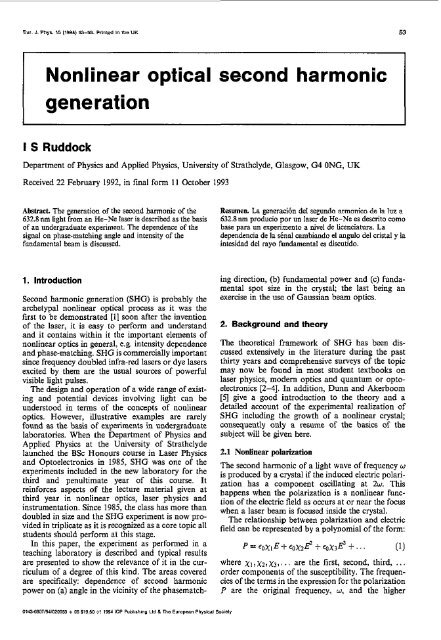
<strong>Nonlinear</strong> <strong>optical</strong> <strong>second</strong> <strong>harmonic</strong><br />
<strong>generation</strong><br />
I S Ruddock<br />
Department of Physics and Applied Physics, University of Strathclyde, Glasgow, G4 ONC, UK<br />
Received 22 February 1992, in final form 11 October 1993<br />
Abstract. The <strong>generation</strong> of the <strong>second</strong> <strong>harmonic</strong> of the<br />
632.8 MI light from ao He-Ne laser is described as the basis<br />
of an undergraduate experiment. The dependence of the<br />
signal on phase-matching angle and intensity of the<br />
fundamental beam is discussed.<br />
Rerumea. La gcnermbn del sepundo ~rmonicn dr In Iuz a<br />
632 8 nm producio por un laser de Hz-h es descnto mmo<br />
bru para un crpenmenio a nivel de hCZnCl31urd La<br />
dependcnas de I3 slnd cambrando el anylo del cnsLaI y la<br />
intesidad del ra,o fundamental ci dxuudo<br />
1. Introduction<br />
Second <strong>harmonic</strong> <strong>generation</strong> (SHG) is probably the<br />
archetypal nonlinear <strong>optical</strong> process as it was the<br />
first to be demonstrated 111 soon after the invention<br />
of the laser, it is easy to perform and understand<br />
and it contains within it the important elements of<br />
nonlinear optics in general, e.g. intensity dependence<br />
and phase-matching. SHG is commercially important<br />
since frequency doubled infra-red lasers or dye lasers<br />
excited by them are the usual sources of powerful<br />
visible light pulses.<br />
The design and operation of a wide range of existing<br />
and potential devices involving light can be<br />
understood in terms of the concepts of nonlinear<br />
optics. However, illustrative examples are rarely<br />
found as the basis of experiments in undergraduate<br />
laboratories. When the Department of Physics and<br />
Applied Physics at the University of Strathclyde<br />
launched the BSc Honours course in Laser Physics<br />
and Optoelectronics in 1985, SHG was one of the<br />
experiments included in the new laboratory for the<br />
third and penultimate year of this course. It<br />
reinforces aspects of the lecture material given at<br />
third year in nonlinear optics, laser physics and<br />
instrumentation. Since 1985, the class has more than<br />
doubled in size and the SHG experiment is now provided<br />
in triplicate as it is recognized as a core topic all<br />
students should perform at this stage.<br />
In this paper, the experiment as performed in a<br />
teaching laboratory is described and typical results<br />
are presented to show the relevance of it in the curriculum<br />
of a degree of this kind. The areas covered<br />
are specifically: dependence of <strong>second</strong> <strong>harmonic</strong><br />
power on (a) angle in the vicinity of the phasematch-<br />
ing direction, (b) fundamental power and (c) fundamental<br />
spot size in the crystal; the last being an<br />
exercise in the use of Gaussian beam optics.<br />
2. Background and theory<br />
The theoretical framework of SHG has been discussed<br />
extensively in the literature during the past<br />
thirty years and comprehensive surveys of the topic<br />
may now be found in most student textbooks on<br />
laser physics, modem optics and quantum or optoelectronics<br />
[2-41. In addition, Dunn and Akerhoom<br />
[5] give a good introduction to the theory and a<br />
detailed account of the experimental realization of<br />
SHG including the growth of a nonlinear crystal;<br />
consequently only a resume of the basics of the<br />
subject will he given here.<br />
2.1 <strong>Nonlinear</strong> polarization<br />
The <strong>second</strong> <strong>harmonic</strong> of a light wave of frequency w<br />
is produced by a crystal if the induced electric polarization<br />
has a component oscillating at 2w. This<br />
happens when the polarization is a nonlinear function<br />
of the electric field as occurs at or near the focus<br />
when a laser beam is focused inside the crystal.<br />
The relationship between polarization and electric<br />
field can be represented by a polynomial of the form:<br />
where xi,xz,x3,, . , are the first, <strong>second</strong>, third, . . .<br />
order components of the susceptibility. The frequencies<br />
of the terms in the expression for the polarization<br />
P are the original frequency, w. and the higher
54 I S Ruddock<br />
frequencies 2w, 3w, ... giving rise to <strong>harmonic</strong>s of the<br />
original frequency w. Because x2, x3,. .. are small<br />
compared with xI, nonlinear <strong>optical</strong> effects were<br />
not observed until after the invention of the laser in<br />
1960.<br />
The simplest way to obtain an expression linking<br />
the <strong>second</strong> <strong>harmonic</strong> intensity with that of the fundamental<br />
and the length of the crystal etc., is to Erst<br />
assume that a wave El of amplitude O,, angular<br />
frequency w, and wave number k,,<br />
E, =Pl[exp i(k,r-qf)+exp-i(k,r-wlt)],<br />
propagates in the z direction through the nonlinear<br />
medium and generates a <strong>second</strong> <strong>harmonic</strong> wave E2<br />
of amplitude 82, angular frequency zWl and wave<br />
number k2,<br />
Ea = P2[exp i(kp - zWl f) + exp -i(kzz - zWlr)],<br />
(2)<br />
Since the amplitude of the <strong>second</strong> <strong>harmonic</strong> grows<br />
with distance z, &t2/az must be deduced and then<br />
integrated over the thickness, 1, of the crystal.<br />
In a nonmagnetic material of permitivity 6, the<br />
wave equation is<br />
2 a2E<br />
V E = PO€-<br />
az<br />
az<br />
= PO- [€DE + PI.<br />
as<br />
For the <strong>second</strong> <strong>harmonic</strong> wave equation, all polarization<br />
wmponents oscillating at zWl must be<br />
included in P and so (3) becomes:<br />
(3)<br />
gating a distance 1 through the crystal is given by<br />
[ iAk ]<br />
- ix2(2w1)8: expiAkl- I<br />
4cn2<br />
(7)<br />
where Ak = k2 - Zk,, the mismatch parameter.<br />
The average <strong>second</strong> <strong>harmonic</strong> intensity generated<br />
at the exit of the crystal, I,, is thus<br />
where use has been made of the general expression<br />
I= L”,”<br />
Only media which lack inversion symmetry, for<br />
example anisotropic crystals, possess non-zero x2.<br />
That this is so can be seen by inspection of equation<br />
(1) since in a centrosymmetric crystal, reversal of the<br />
electric field must leave the magnitude of the polarization<br />
unchanged. A consequence of a crystal being<br />
anisotropic is that it exhibits birefringence, but this<br />
in turn can be exploited to produce ‘phasematching’<br />
resulting in the efficient <strong>generation</strong> of the nonlinear<br />
signal.<br />
2.2 Phasematching<br />
If Ak # 0, as is normally the case due to dispersion,<br />
then the average <strong>second</strong> <strong>harmonic</strong> intensity, I, is proportional<br />
to sin2(Akl/2) and it oscillates with distance<br />
through the crystal. The <strong>second</strong> <strong>harmonic</strong><br />
-1<br />
ir (4) waves generated at different points along the beam’s<br />
V2E2 = I.L~~~~~~[E~+xIE~+x~~I.<br />
The quantities within the brackets represent<br />
respectively, the linear pola,+zation contrim<br />
bution due to the <strong>second</strong> <strong>harmonic</strong> Wave itself<br />
and the nonlinear driving term produced by the<br />
fundamental.<br />
Recognizing that the refractive index at the<br />
<strong>second</strong> <strong>harmonic</strong>, n2 is related to the susceptibility<br />
evaluated at zW,, by n: = 1 + x,, (4) may be written<br />
as<br />
a2<br />
V2E2 =poeo-[n2E +xzEI]. 2<br />
a<br />
At the intensity levels encountered in these experiments,<br />
the conversion efficiency is low and thus the<br />
<strong>second</strong> <strong>harmonic</strong> amplitude grows slowly with<br />
distance through the capital. In this case it may be<br />
assumed that #8,/az2 < k2.a82/az, then substitution<br />
of (2) as the solution of the <strong>second</strong> <strong>harmonic</strong><br />
wave equation (5) yields<br />
path do not reinforce each other as they are not<br />
travelling at the same speed as the fundamental wave.<br />
Chaotic interference occurs and the <strong>second</strong> <strong>harmonic</strong><br />
wave does not succeed in growing in intensity. If<br />
however, Ak=o,<br />
(9)<br />
and I, is proportional to l2 giving rapid growth of the<br />
<strong>second</strong> <strong>harmonic</strong> intensity with distance. Phasematching<br />
is said to occur under these conditions as<br />
the refractive indices and phase velocities at the fundamental<br />
and <strong>second</strong> <strong>harmonic</strong> Frequencies are equal<br />
and thus X2 = XI 12.<br />
The crystal used in this experiment, Ammonium<br />
Dihydrogen Phosphate (ADP), is negatively uniaxial<br />
with no > n. and its dispersion curves are shown<br />
schematically in figure 1. It is clear that there exists<br />
in this crystal a direction 9 relative to the optic axis<br />
such that the ordinary index at XI is equal to the<br />
extraordinary at A,, given by
<strong>Nonlinear</strong> <strong>optical</strong> <strong>second</strong> <strong>harmonic</strong> <strong>generation</strong> 55<br />
.t \<br />
Figure 1. The wavelength dependence of refractive index<br />
for a negatively uniaxial crystal such as ADP. At M angle<br />
B to the optic axis, the ordinary index at the fundamental<br />
wavelength, A, is equal w the extraordinary at the <strong>second</strong><br />
<strong>harmonic</strong> wavelength, A,.<br />
The opposite scheme applies in a positive uniaxial<br />
crystal although both cases are referred to as Type<br />
1 phasematching. Type 2 occurs when both ordinary<br />
and extraordinary fundamental photons combine to<br />
produce the <strong>second</strong> <strong>harmonic</strong>.<br />
3. Experimental arrangement<br />
Figure 2 shows schematically the basic set-up<br />
required for the observation of SHG by a 632.8 nm<br />
He-Ne laser. The plane polarized 2mW laser beam<br />
is focused by a x 10 microscope objective into an<br />
ADP crystal positioned on a turntable. The objective<br />
is in a threaded flange with a rack and pinion<br />
adjnstment so that the focus of the laser beam can<br />
be tracked through the crystal. The position of the<br />
lens relative to the crystal is measurable to a precision<br />
of 5 pm by means of a standard engineer's dial<br />
gauge indicator.<br />
The UV light generated is detected by a<br />
Hamamatsu IP28 photomultiplier tube through a<br />
Schott Glass UGll fdter to block the red laser<br />
light. A 632.8nm interference filter is also necessary<br />
to reject the intense blue and UV radiation emitted<br />
by the front mirror of the He-Ne laser which would<br />
otherwise obscure the sewnd <strong>harmonic</strong>. Although<br />
the signal is sufficiently strong for an oscilloscope<br />
to be more than adequate for locating it and making<br />
quantitative measurements, it is also convenient to<br />
chop the laser beam and use a lock-in amplifier or<br />
gated integrator. We have found the Bentham<br />
Model 223 amplifier and Delta Developments<br />
chopped signal integrator to be suitable for this<br />
purpose.<br />
The entire experiment is assembled on a single<br />
triangular <strong>optical</strong> bench using simple saddles and<br />
components as available from Precision Tool and<br />
Instrument CO Ltd, except for the crystal turntable<br />
which was supplied by Ealing Electro-optics and<br />
has a Vernier angle scale. The x 10 microscope ohjective<br />
(Ealing Cat. No 11-8265) is a low-cost flat<br />
mounted lens with a large working distance enabling<br />
the crystal to be rotated at the focus of the laser<br />
beam.<br />
The ADP crystals used here are 2.15 and 0.36mm in<br />
thickness and are cut approximately for Type 1<br />
phase-matching at 633 nm. Since ADP is negatively<br />
uniaxial, the crystal and laser must he orientated relative<br />
to each other such that the light is always incident<br />
in the ordinary polarization plane as the<br />
crystal is rotated; this is accomplished by rotating<br />
the crystal about an axis parallel to the plane of<br />
polarization of the laser beam but perpendicular to<br />
the plane containing the crystal's optic axis (see<br />
figure 2). If suitable nonlinear crystals are not available,<br />
samples of urea may be easily grown in a couple<br />
of days in a beaker and used straightaway without<br />
polishing; at room temperature and a wavelength of<br />
632.8 MI, the phasematching scheme is Type 2 (see<br />
[SI for experimental details).<br />
4. Experiments<br />
SHG is immediately apparent if the laser is focused<br />
on the crystal, which is being rotated while the photomultiplier<br />
outpnt is observed on an oscilloscope. If<br />
for any reason the effect is difficult to observe, the<br />
lock-in amplifier phase can be correctly adjusted by<br />
first removing the interference filter and then detecting<br />
the chopped spontaneous emission from the laser<br />
discharge.<br />
,I<br />
,I<br />
U<br />
Figure 2. Experimental arrangement for<br />
generating and detecting the <strong>second</strong> <strong>harmonic</strong>
56 I S Ruddock<br />
4.1 Phasematching angle<br />
Intense <strong>second</strong> <strong>harmonic</strong> is only generated when the<br />
fundamental and <strong>second</strong> <strong>harmonic</strong> waves are travelling<br />
at the same phase velocity within the crystal.<br />
As outlined in the theory this can be arranged by<br />
exploiting the birefringence of the crystal to find a<br />
direction in which the refractive indices are the<br />
same. Data points (a) in figure 3 show the variation<br />
in <strong>second</strong> <strong>harmonic</strong> power with angle of incidence<br />
for the thin crystal. Depending on the accuracy of<br />
the cut of a crystal, the angle of incidence may be<br />
quite small; ideally it should be zero.<br />
The angular tolerance for a particular set-up is<br />
more properly demonstrated by converting the<br />
measured angles of incidence to the corresponding<br />
angles of refraction by Snell's law; the refractive<br />
index of the crystal at 632.8~11 being obtained from<br />
the Sellmeier equation [6]. Data points (b) show the<br />
<strong>second</strong> <strong>harmonic</strong> power as a function of internal<br />
angle which as expected is considerably narrower<br />
than that of the external, due solely to refraction.<br />
The residual width of the peak is a measure of the<br />
laser beam's convergence and divergence as it passes<br />
through the crystal.<br />
If the phasematching angle, i.e. the angle between<br />
the crystal's optic axis and the direction of light propagation,<br />
is calculated using (IO), it is also instructive<br />
for students to deduce, from their measurement of<br />
the angle of incidence, the possible directions of the<br />
optic axis within their crystal samples.<br />
4.2. lntensiiy dependence<br />
42.1. Laser power. Since SHG is mediated by the<br />
<strong>second</strong> component, xz, in the expansion of the<br />
susceptibility, the <strong>harmonic</strong> intensity generated is<br />
proportional to the square of the fundamental<br />
intensity. If, as is usually the case, the beam crosssectional<br />
area is kept constant, then the signal is<br />
Flgure 3. Dependence of the <strong>second</strong> <strong>harmonic</strong> signal on<br />
(a) the fundamental beam's angle of incidence on the<br />
crystal and @) the angle of refraction for an ADP crystal<br />
of thickness 0.36mm. The angles of incidence and<br />
refraction are related by Snell's law evaluated using the<br />
ordinary refractive index at 632.8 om.<br />
1<br />
+I t .<br />
proportional to the square of the laser power.<br />
Although laboratory He-Ne lasers are normally of<br />
fmed power outputs, they can be easily controlled by<br />
means of neutral density (ND) filters. With NDs of<br />
0.1, 0.2, 0.4 and I used singly and in combination,<br />
transmissions of0.80,0.63,0.50,0.40,0.32,0.25,0.20<br />
and 0.10 can be selected to conveniently control the<br />
laser power incident on the crystal. (See [5] for the use<br />
of polarizers for this purpose.) The <strong>second</strong> <strong>harmonic</strong><br />
power as a function of the incident laser power is<br />
shown plotted in figure 4. The parabolic nature of the<br />
curve is apparent and is easily confirmed by<br />
replotting as an In-ln graph (figure 5). Most of the<br />
points fit well to a line of slope 2.<br />
4.2.2. Beam cross-sectional area. The intensity<br />
dependence can also be demonstrated by varying<br />
the size of the focused laser spot. This is achieved by<br />
moving the microscope objective relative to the<br />
noalinear crystal. The subsequent analysis uses the<br />
propagation equations for Gaussian beams, theory<br />
normally dealt with in a Laser Physics lecture course<br />
but not often applied in an undergraduate<br />
laboratory. Typical results for when the lens is<br />
moved by k2.5mm on either side of the position of<br />
maximum <strong>second</strong> <strong>harmonic</strong> signal are shown in<br />
figure 6, data points (a) and @) for the thick and thin<br />
crystals respectively. The dramatic increase in the<br />
efficiency of the <strong>second</strong> <strong>harmonic</strong> process as the<br />
tightest Focus passes through the crystal is clearly<br />
illustrated.<br />
From (9) and section 4.2.1, the <strong>second</strong> <strong>harmonic</strong><br />
intensity, la, is proportional to the square of the fundamental<br />
intensity, If. Now, if the laser spot in the<br />
crystal is approximated to be a disc of radius IV of<br />
uniform intensity, then I2 is clearly inversely proportional<br />
to w4. However, Iz as described by (8) is the<br />
intensity of the <strong>second</strong> <strong>harmonic</strong> beam as it exits<br />
the crystal and not that at the aperture of the photomultiplier.<br />
As long as this is greater than the beam<br />
diameter, the quantity detected is the spatially<br />
integrated <strong>second</strong> <strong>harmonic</strong> intensity, i.e. the average<br />
<strong>second</strong> <strong>harmonic</strong> power, P2. At the crystal, the two<br />
Figure 4. Dependence of the <strong>second</strong> <strong>harmonic</strong> signal on<br />
the fundamental power: linear plot.<br />
i +<br />
t<br />
I
~<br />
<strong>Nonlinear</strong> <strong>optical</strong> <strong>second</strong> <strong>harmonic</strong> <strong>generation</strong><br />
57<br />
Figure 5. Dependence of the <strong>second</strong> <strong>harmonic</strong> signal on<br />
the fundamental power: In-In plot. The stmight line is of<br />
slope 2.<br />
quantities are related by PZ = I 2 . d and hence the<br />
<strong>second</strong> <strong>harmonic</strong> signal is inversely proportional to<br />
wz for constant laser power.<br />
Figure 7 shows schematically the Gaussian<br />
beam expanding from the output of the laser and<br />
being focused by a lens of focal length f to a spot<br />
of radius w0. The beam spot size, w(z), a distance z<br />
symmetrically on either side of the focus given by<br />
[2-41<br />
w(z) = WO [ I +<br />
(3'1 -<br />
The spot sue 'w' denotes the I/e radius of<br />
the electric field distribution and the l/ez radius<br />
of the light intensity in the cross-section of a<br />
fundamental mode Gaussian beam. The size of<br />
the light spot at the focus, WO, is determined by<br />
the focal length of the lens and the spot radius, w2,<br />
of the light incident on it. By application of<br />
the ABCD ray tracing matrices for the lens and<br />
the displacement between it and the focal point,<br />
wo may be shown to be given by [7]<br />
For the dimensions encountered in most practical<br />
situations, (12) can be simplified to<br />
Figure 6. Dependence of the <strong>second</strong> <strong>harmonic</strong> signal on<br />
the position of the crystal relative to the focus of the lens<br />
at z = 0 for crystals of thickness (a) 2.16- and (b)<br />
0.36mm. The solid curve is W(Z)-~ evaluated using only<br />
the measured parameters of the experiment.<br />
Since wz is in turn due to the divergence and diffraction<br />
of the beam expanding from the beam<br />
waist, w,, located either on one of the laser mirrors<br />
or at some point between them, it may be calculated<br />
by using (1 I ) again. The manufacturer's specification<br />
for an He-Ne laser normally quotes wI or at<br />
least the far field beam divergence and so the spot<br />
size in the vicinity of the focus can be traced back<br />
to the laser itself.<br />
The laser used in the experiment Melles-Griot 05<br />
LHP 121, bas a l/e2 beam radius (wl) of 0.2951~1.<br />
Application of (1 1) yields a spot radius of 0.505 mm<br />
(wz) at the input of the lens when it is 60cm from<br />
the laser. The Ealing x 10 objective has an equivalent<br />
focal length of 16" which results in a focus of<br />
radius (wo) of 6.39 pm. Thus the variation in the spot<br />
size on either side of the focus, ~ (z), is given by ( I 1)<br />
to be<br />
w(z) = 6.39pm [ 1 + 24.3 (14)<br />
To fit theoretical curves to the experimental points,<br />
w(z)-' is evaluated from (14) over the same range of<br />
lens adjustment and is shown plotted as the solid<br />
cume in figure 6.<br />
The agreement of the computed points is exceptionally<br />
good for the thin sample hut poor for the<br />
thick one. The model effectively assumed that the<br />
<strong>second</strong> <strong>harmonic</strong> was only generated in an infinitesimally<br />
thin slice of crystal. In practice, the conver-<br />
Laser<br />
1<br />
2Wl<br />
Figure 7. Schematic view of the fundamental<br />
beam diverging from the aperture of the laser<br />
and being focused by the microscope<br />
objective to a beam waist of spot diameter<br />
2w". At a distance z from the focus, the<br />
beam spot diameter is 2w(+ 2~7, 2w2, and<br />
2w3(= 2w2) are the spot diameten at the<br />
laser and input and output planes of the lens<br />
respectively.
~~<br />
58 I S Ruddock<br />
sion effciency is high provided the focus is still<br />
located within the crystal and so in the latter case,<br />
the curve is a measure of the crystal's thickness<br />
(- 2"). When the sample is thin, the variation in<br />
beam spot radius through it is negligible and hence<br />
the simple model applies.<br />
5. Conclusions<br />
An undergraduate experiment featuring the phenomenon<br />
of <strong>second</strong> <strong>harmonic</strong> <strong>generation</strong> of a laser has<br />
been described. The experiment illustrates the hasic<br />
principles of the process, phasematching and power<br />
dependence. In addition, it includes an exercise<br />
requiring the application of Gaussian beam optics<br />
and illustrating well some calculations which a<br />
graduate scientist working in this field would be<br />
expected to perform from time to time.<br />
References<br />
111 Franken PA. Hill A E, Peters C W and Weinreich<br />
G 1961 Phys. Rev. Left. 7 118<br />
[2] Guenther R 1990 Modem Optics(New York Wiley)<br />
[3] Yariv A 1985 Opticul Elecrronics 3rd cdn (Holt-<br />
Saunders)<br />
[4] Chatak A K and Thyagarajan K 1989 Optical<br />
Electronics (Cambridge: Cambridge University<br />
Press)<br />
[5l Dunn M H and Akerboom F 1985 Oprical<strong>second</strong><br />
hnrmonic <strong>generation</strong>. Physics Experiments and<br />
Projecb for Studenfs ed C Isenberg and S Chomet<br />
(Newman Hemisphere)<br />
[a Kirby K W and DeShazer L G 1987 J. Opi. Soc.<br />
Am. B 4 1072<br />
[I Verdeyen J T 1981 her Electronics (Englewood<br />
Cliffs, NJ: PrentiwHall). This undergraduate<br />
textbook gives a good introduction to Gaussian<br />
beam optics and ray tracing matrices, and deals<br />
with the focusing of a laser beam as a worked<br />
example