DSP7 - Duplomatic
DSP7 - Duplomatic
DSP7 - Duplomatic

You also want an ePaper? Increase the reach of your titles
YUMPU automatically turns print PDFs into web optimized ePapers that Google loves.
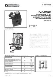
41 420/112 ED<br />
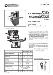
<strong>DSP7</strong><br />
PILOT OPERATED DISTRIBUTOR<br />
SOLENOID OR HYDRAULIC<br />
(DSC7) CONTROLLED<br />
SUBPLATE MOUNTING<br />
ISO 4401-07 (CETOP 07)<br />
p max 350 bar<br />
Q max 300 l/min<br />
MOUNTING INTERFACE<br />
ISO 4401-07-07-0-05<br />
(CETOP 4.2-4-07-350)<br />
15.9<br />
14.3<br />
1.6<br />
18.3<br />
101.6<br />
88.1<br />
76.6<br />
65.9<br />
50<br />
34.1<br />
G<br />
71.5<br />
69.8<br />
57.2<br />
55.6<br />
34.9<br />
Ø17.5 (max)<br />
L<br />
G<br />
T<br />
A<br />
M6<br />
P<br />
X<br />
B<br />
Y<br />
Ø4<br />
M10<br />
Ø6.3 (max)<br />
— The <strong>DSP7</strong> piloted valve is made up of a 4-way hydropiloted<br />
distributor with mounting surface according to<br />
ISO 4401-07 (CETOP 07) (CETOP RP121H) standards,<br />
operated by an ISO 4401-03 (CETOP 03) solenoid<br />
directional valve.<br />
— It is available with different spool types (see par. 2), with<br />
some options for the opening control.<br />
— It is available with both the solenoid and the hydraulic<br />
control from the X and Y ways<br />
— A version for high pressures (H) is available.<br />
PERFORMANCES (obtained with mineral oil of viscosity of 36 cSt at 50°C)<br />
Maximum operating pressure<br />
- ports P - A - B<br />
- port T (external drainage)<br />
- port T (internal drainage)<br />
41 420/112 ED 1/12<br />
bar<br />
<strong>DSP7</strong><br />
Maximum flow rate from port P to A - B - T l/min 300<br />
Ambient temperature range °C -20 / +50<br />
Fluid temperature range °C -20 / +80<br />
Fluid viscosity range cSt 10 ÷ 400<br />
350<br />
210<br />
140<br />
<strong>DSP7</strong>H<br />
Fluid contamination degree according to ISO 4406:1999 class 20/18/15<br />
Recommended viscosity cSt 25<br />
Mass:<br />
<strong>DSP7</strong>-S, RK<br />
<strong>DSP7</strong>-T*, SA*, SB*<br />
DSC7<br />
kg<br />
8,6<br />
8,0<br />
6,6<br />
420<br />
350<br />
140
<strong>DSP7</strong><br />
1 - IDENTIFICATION CODE FOR SOLENOID DISTRIBUTOR <strong>DSP7</strong><br />
D S P 7 - / 20 - / / K1 /<br />
Directional valve,<br />
Solenoid controlled,<br />
Pilot operated<br />
Size:<br />
ISO 4401-07 (CETOP 07)<br />
Manual override:<br />
omit for override<br />
integrated in the tube<br />
(standard)<br />
CM = manual override,<br />
boot protected (see<br />
paragraph 14)<br />
Option: (omit for standard version)<br />
H = high pressure version<br />
pmax = 420 bar<br />
not available with S4, SA4, SB4 spools.<br />
Spool type (see paragraph 2)<br />
S* TA<br />
SA* TB<br />
SB* RK<br />
Series: (the overall and mounting dimensions<br />
remain unchanged from 20 to 29)<br />
Seals:<br />
N = NBR seals for mineral oil (standard)<br />
V = FPM seals for special fluids<br />
Piloting (see paragraph 9):<br />
I = internal (not available for spools S2 - S4 - S7 - S8 - TA02<br />
TB02 -RK02 - S*2 - S*4. If internal pilot is required, choose pilot type C)<br />
C= internal piloting with backpressure valve<br />
Z = internal piloting with 30 bar fixes adjustment pressure reducing valve<br />
(see paragraph 8)<br />
E = external<br />
Coil electrical<br />
connection:<br />
plug for connector<br />
type DIN 43650<br />
(standard)<br />
DC power supply<br />
D12 = 12 V<br />
D24 = 24 V<br />
D48 = 48 V<br />
D110 = 110 V<br />
D220 = 220 V<br />
D00 = valve without coils (see NOTE)<br />
AC power supply<br />
A24 = 24 V - 50 Hz<br />
A48 = 48 V - 50 Hz<br />
A110 = 110 V - 50 Hz / 120 V - 60 Hz<br />
A230 = 230 V - 50 Hz / 240 V - 60 Hz<br />
A00 = valve without coils (see NOTE)<br />
F110 = 110 V - 60 Hz<br />
F220 = 220 V - 60 Hz<br />
Drainage (see paragraph 9):<br />
I = Internal<br />
E = External<br />
Controls:<br />
C = Main spool stroke control (see paragraph 13.1)<br />
D = Main spool switching speed control (see paragraph 13.2)<br />
P08 = Subplate placed under solenoid valve with restrictor of Ø0.8 on port P<br />
(see paragraph 13.3)<br />
S2 = Distributor delivered with pilot solenoid valve in configuration S2<br />
(see paragraph 13.4)<br />
NOTE: The locking rings of the coils and the relevant O-Rings are supplied together with valves<br />
41 420/112 ED 2/12
<strong>DSP7</strong><br />
2 - SPOOL TYPE<br />
NOTE: Symbols refers to the <strong>DSP7</strong> solenoid valve.<br />
For the DSC7 hydraulic control version, please verify the connection scheme at paragraph 3.<br />
Type S*:<br />
2 solenoids - 3 positions<br />
with spring centering<br />
Type SA*:<br />
1 solenoid side A<br />
2 positions (central + external)<br />
with spring centering<br />
Type SB*:<br />
1 solenoid side B<br />
2 positions (central + external)<br />
with spring centering<br />
A<br />
B<br />
A<br />
B<br />
A<br />
B<br />
a<br />
a<br />
P<br />
0<br />
T<br />
b<br />
b<br />
a<br />
a<br />
P<br />
0<br />
T<br />
P<br />
0<br />
T<br />
b<br />
b<br />
S1<br />
SA1<br />
SB1<br />
S2<br />
SA2<br />
SB2<br />
S3<br />
SA3<br />
SB3<br />
S4<br />
SA4<br />
SB4<br />
S6<br />
S7<br />
S8<br />
S9<br />
S10<br />
S11<br />
Type TA:<br />
1 solenoid side A<br />
2 external positions<br />
with return spring<br />
Type TB:<br />
1 solenoid side B<br />
2 external positions<br />
with return spring<br />
S12<br />
S20<br />
a<br />
a<br />
A<br />
P<br />
b<br />
B<br />
T<br />
A<br />
P<br />
a<br />
B<br />
T<br />
b<br />
b<br />
S21<br />
TA<br />
TB<br />
TA02<br />
TB02<br />
Type RK:<br />
2 solenoids - 2 positions<br />
with mechanical retention<br />
Type TA23 / TB23<br />
three-way valve - 1 solenoid - 2 external positions, return spring<br />
A<br />
B<br />
A<br />
B<br />
A<br />
B<br />
a<br />
a<br />
P<br />
b<br />
T<br />
b<br />
a<br />
a<br />
P<br />
b<br />
T<br />
P<br />
a<br />
T<br />
b<br />
b<br />
RK<br />
TA23<br />
TB23<br />
RK02<br />
Besides the diagrams shown, which are the most frequently used, other special versions are available:<br />
consult our technical department for their identification, feasibility and operating limits.<br />
41 420/112 ED 3/12
<strong>DSP7</strong><br />
3 - IDENTIFICATION CODE FOR HYDRAULIC DISTRIBUTOR DSC7<br />
D S C 7 - / 10 -<br />
E E<br />
Directional valve,<br />
hydraulic controlled<br />
pilot operated through X<br />
and Y ports.<br />
External drain (see par. 9)<br />
External pilot (see par. 9)<br />
Size: ISO 4401-07 (CETOP 07 )<br />
Option: (omit for standard version)<br />
H = high pressure version<br />
pmax = 420 bar<br />
not available with S4, SA4, SB4 spools.<br />
Spool type (see paragraph 2)<br />
S* TA<br />
SA* TB<br />
SB* R<br />
Seals:<br />
N = NBR seals for mineral oil<br />
(standard)<br />
V = FPM seals for special fluids<br />
Series: (the overall and mounting dimensions<br />
remain unchanged from 10 to 19)<br />
Spool type<br />
The distributor is delivered with short-circuit subplate. The X and Y ports are<br />
used for the hydraulic control of the valve.<br />
4 - HYDRAULIC FLUIDS<br />
Use mineral oil-based hydraulic fluids HL or HM type, according to ISO 6743-4. For these fluids, use NBR seals (code N). For fluids HFDR type<br />
(phosphate esters) use FPM seals (code V).<br />
For the use of other kinds of fluid such as HFA, HFB, HFC, please consult our technical department. Using fluids at temperatures higher than<br />
80 °C causes a faster degradation of the fluid and of the seals characteristics.<br />
The fluid must be preserved in its physical and chemical characteristics.<br />
41 420/112 ED 4/12
<strong>DSP7</strong><br />
5 - PRESSURE DROPS ∆p-Q (values obtained with viscosity 36 cSt at 50 °C)<br />
PRESSURE DROPS WITH VALVE ENERGIZED<br />
FLOW DIRECTION<br />
SPOOL TYPE P-A P-B A-T B-T<br />
CURVES ON GRAPH<br />
S1, SA1, SB1 1 1 3 4<br />
S2, SA2, SB2 1 1 4 4<br />
S3, SA3, SB3 1 1 4 4<br />
S4, SA4, SB4 2 2 4 5<br />
S6 1 1 3 4<br />
S7 1 1 4 4<br />
S8 1 1 3 4<br />
S9 1 1 3 4<br />
S10 1 1 3 4<br />
S11 1 1 3 4<br />
S12 1 1 3 4<br />
S20 1 1 3 4<br />
S21 1 1 4 4<br />
TA, TB 1 1 3 4<br />
TA02, TB 02 1 1 4 4<br />
RK 1 1 3 4<br />
PRESSURE DROPS WITH VALVE IN DE-ENERGIZED POSITION<br />
FLOW DIRECTION<br />
SPOOL TYPE P-A P-B A-T B-T P-T<br />
CURVES ON GRAPH<br />
S2, SA2, SB2 6<br />
S3, SA3, SB3 7 7<br />
S4, SA4, SB4 7<br />
S6 7<br />
S7 8<br />
S8 8<br />
S10 7 7<br />
S11 7<br />
6 - SWITCHING TIMES<br />
The values indicated refer to a solenoid valve working with piloting<br />
pressure of 100 bar, with mineral oil at a temperature of 50°C, at<br />
viscosity of 36 cSt and with PA and BT connections. The energizing<br />
and de-energizing times are obtained at the pressure variation<br />
which occurs on the lines.<br />
TIMES (± 10%) ENERGIZED DE-ENERGIZED<br />
[ms] 2 Pos. 3 Pos. 2 Pos. 3 Pos.<br />
AC solenoid 45 30 45 30<br />
DC solenoid 75 60 60 45<br />
41 420/112 ED 5/12
<strong>DSP7</strong><br />
7 - OPERATING LIMITS<br />
The curves define the flow rate operating fields according to the valve pressure for the different spool types.<br />
The values have been obtained according to ISO 6403 norm with solenoids at rated temperature and supplied with voltage equal to 90% of the<br />
nominal voltage.<br />
The values have been obtained with mineral oil, viscosity 36 cSt at 50 °C, and filtration ISO 4406:1999 class 18/16/13.<br />
SPOOL TYPE CURVE<br />
P-A P-B<br />
S1,SA1,SB1 1 1<br />
S2, SA2, SB2 1 1<br />
S3, SA3, SB3 1 1<br />
S4, SA4, SB4 2 2<br />
S6 1 1<br />
S7 2 2<br />
S8 2 2<br />
SPOOL TYPE CURVE<br />
P-A P-B<br />
S9 1 1<br />
S10 1 1<br />
S11 1 1<br />
S12 1 1<br />
S20 1 1<br />
S21 1 1<br />
TA, TB 1 1<br />
TA02, TB02 1 1<br />
TA23, TB23 1 1<br />
RK 1 1<br />
8 - PERFORMANCE CHARACTERISTICS<br />
PRESSURES [bar] <strong>DSP7</strong> <strong>DSP7</strong>H DSC7 DSC7H<br />
MIN<br />
MAX<br />
Pressure in P, A, B ports 350 420 350 420<br />
Piloting pressure (X port and / or Y port) 12 (a) 210 (b) 350 210 350<br />
Pressure in T line with internal drainage - 140 140 - -<br />
Pressure in T line with external drainage - 210 350 210 350<br />
NOTES:<br />
a) The minimum piloting pressure can be of 6 bar at low flows rates, but with higher flow rates a pressure of 12 bar is needed.<br />
b) If the valve operates with higher pressures it is necessary to use the version with external pilot and reduced pressure. Otherwise, the valve<br />
with internal pilot and pressure reducing valve with 30 bar fixed adjustment can be ordered.<br />
41 420/112 ED 6/12
<strong>DSP7</strong><br />
9 - PILOTING AND DRAINAGE<br />
The <strong>DSP7</strong> valves are available with piloting and drainage, both internal and external.<br />
The version with external drainage allows for a higher back pressure on the outlet.<br />
IE<br />
II<br />
EE<br />
EI<br />
TYPE OF VALVE<br />
INTERNAL PILOT AND<br />
EXTERNAL DRAIN<br />
INTERNAL PILOT AND<br />
INTERNAL DRAIN<br />
EXTERNAL PILOT AND<br />
EXTERNAL DRAIN<br />
EXTERNAL PILOT AND<br />
INTERNAL DRAIN<br />
Plug assembly<br />
X Y<br />
NO YES<br />
NO NO<br />
YES YES<br />
YES NO<br />
X: plug M6x8 for external pilot<br />
Y: plug M6x8 for external drain<br />
9.1 - Backpressure valve incorporated on line P<br />
Valves <strong>DSP7</strong> are available upon request with backpressure valve incorporated on line P. This is necessary to obtain the piloting pressure when<br />
the control valve, in rest position, has the line P connected to the T port (spools S2, S4, S7, S8, S*2, S*4, TA02, TB02, RK02). The cracking<br />
pressure is of 5 bar with a minimum flow rate of 15 l/min.<br />
Add C to the identification code for this request (see paragraph 1).<br />
In the C version the piloting is always internal.<br />
The backpressure valve can be also delivered separately and it can be easily mounted on line P of the main control valve. Specify the code<br />
0266577 to order the backpressure valve separately.<br />
<strong>DSP7</strong>-C<br />
pilot always internal<br />
Y: plug M6x8 for external drain<br />
NOTE: the backpressure valve can’t be used as<br />
check valve because it doesn’t assure the seal.<br />
The curve refers to the pressure drop (body part<br />
only) with backpressure valve energized to which<br />
the pressure drop of the reference spool must be<br />
added. (see paragraph 5)<br />
41 420/112 ED 7/12
<strong>DSP7</strong><br />
10 - ELECTRICAL FEATURES<br />
10.1 Solenoids<br />
These are essentially made up of two parts: tube and coil. The<br />
tube is threaded into the valve body and includes the armature that<br />
moves immersed in oil, without wear. The inner part, in contact with<br />
the oil in the return line, ensures heat dissipation.<br />
The coil is fastened to the tube by a threaded ring, and can be<br />
rotated 360°, to suit the available space.<br />
NOTE 1: In order to further reduce the emissions, use of type H<br />
connectors is recommended. These prevent voltage peaks on<br />
opening of the coil supply electrical circuit (see CAT. 49 000).<br />
NOTE 2: The IP65 protection degree is guaranteed only with the<br />
connector correctly connected and installed.<br />
VOLTAGE SUPPLY FLUCTUATION<br />
MAX SWITCH ON FREQUENCY<br />
± 10% Vnom<br />
10.000 ins/hr<br />
DUTY CYCLE 100%<br />
ELECTROMAGNETIC COMPATIBILITY<br />
(EMC) (NOTE 1)<br />
LOW VOLTAGE<br />
CLASS OF PROTECTION:<br />
Atmospheric agents (CEI EN 60529)<br />
Coil insulation (VDE 0580)<br />
Impregnation: CC valve<br />
CA valve<br />
In compliance with<br />
2004/108/CE<br />
In compliance with<br />
2006/95/CE<br />
IP 65 (NOTE 2)<br />
class H<br />
class F<br />
class H<br />
10.2 Current and absorbed power for DC<br />
solenoid valve<br />
The table shows current and power consumption values<br />
relevant to the different coil types for DC.<br />
The rectified current supply takes place by fitting the<br />
valve (with the exception of D12 coil) with an alternating<br />
current source (50 or 60 Hz), rectified by means of a<br />
bridge built-in to the “D” type connectors (see cat.<br />
49 000), by considering a reduction of the operating<br />
limits by 5 ÷ 10% approx.<br />
Coils for direct current (values ± 5%)<br />
Suffix Nominal Resistance Current Power Coil<br />
voltage at 20°C consumpt. consumpt. code<br />
[V] [ohm] [A] [W]<br />
D12 12 4,4 2,72 32,7 1903080<br />
D24 24 18,6 1,29 31 1903081<br />
D48 48 78,6 0,61 29,5 1903083<br />
D110 110 423 0,26 28,2 1903084<br />
D220 220 1692 0,13 28,2 1903085<br />
10.3 Current and absorbed power for AC solenoid valve<br />
The table shows current and power consumption values at inrush and at holding, relevant to the different coil types for AC current.<br />
Coils for alternating current (values ± 5%)<br />
Suffix Nominal Frequency Resistance Current Current Power Power Coil<br />
voltage at 20°C consumption consumption consumption consumption code<br />
at inrush at holding at inrush at holding<br />
[V] [Hz] [ohm] [A] [A] [VA] [VA]<br />
A24 24 50 1,46 8 2 192 48 1902830<br />
A48 48 50 5,84 4,4 1,1 204 51 1902831<br />
A110<br />
110V-50Hz<br />
120V-60Hz<br />
1,84<br />
1,56<br />
0,46<br />
0,39<br />
192<br />
188<br />
48<br />
47<br />
32<br />
1902832<br />
A230<br />
230V-50Hz<br />
50/60<br />
0,76 0,19 176 44<br />
240V-60Hz<br />
140<br />
0,6 0,15 144 36<br />
1902833<br />
F110 110<br />
26 1,6 0,4 176 44 1902834<br />
60<br />
F220 220 106 0,8 0,2 180 45 1902835<br />
41 420/112 ED 8/12
<strong>DSP7</strong><br />
11 - OVERALL AND MOUNTING DIMENSIONS FOR SOLENOID DISTRIBUTOR <strong>DSP7</strong><br />
<strong>DSP7</strong>-S<br />
<strong>DSP7</strong>-RK<br />
solenoid position<br />
configuration TB/SB*<br />
<strong>DSP7</strong>-TA<br />
<strong>DSP7</strong>-SA*<br />
<strong>DSP7</strong>-*/20*-Z*<br />
dimensions in mm<br />
Fastening of single valve: 4 SHC screws ISO 4762 M10x60<br />
(see par. 16)<br />
2 SHC screws ISO 4762 M6x50<br />
Tightening M10x60: 40 Nm (A 8.8 screws) - 67 Nm (A 12.9 screws)<br />
torque: M6x50: 8 Nm (A 8.8 screws) - 14 Nm (A 12.9 screws)<br />
Threads of mounting holes: M6x12; M10x18<br />
Sealing rings: 4 OR type 130 (22.22X2.62) - 90 Shore<br />
2 OR type 2043 (10.82x1.78) - 90 Shore<br />
1 Mounting surface with sealing rings<br />
2 Manual override<br />
3 Coil removal space<br />
4 Connector removal space<br />
5 Electric connector to be ordered separately<br />
(see cat. 49 000)<br />
6 Reducing valve with fixed adjustment 30 bar<br />
NOTE: Use of class 12.9 fastening screws is recommended for valves in version H (high pressure).<br />
41 420/112 ED 9/12
<strong>DSP7</strong><br />
12 - OVERALL AND MOUNTING DIMENSIONS FOR HYDRAULIC DISTRIBUTOR DSC7<br />
17<br />
114<br />
Fastening of single valve: 4 SHC screws ISO 4762 M10x60<br />
(see par. 16)<br />
2 SHC screws ISO 4762 M6x50<br />
dimensions in mm<br />
Tightening M10x60: 40 Nm (A 8.8 screws) - 67 Nm (A 12.9 screws)<br />
torque: M6x50: 8 Nm (A 8.8 screws) - 14 Nm (A 12.9 screws)<br />
Threads of mounting holes: M6x12; M10x18<br />
Sealing rings: 4 OR type 130 (22.22X2.62) - 90 Shore<br />
2 OR type 2043 (10.82x1.78) - 90 Shore<br />
1 Mounting surface with sealing rings<br />
2 Short-circuit subplate<br />
NOTE: Use of class 12.9 fastening screws is recommended for valves in version H (high pressure).<br />
41 420/112 ED 10/12
<strong>DSP7</strong><br />
13 - OPTIONS<br />
13.1 Control of the main spool stroke: C<br />
With the help of special side plugs, it is possible to introduce stroke controls in the<br />
heads of the piloted valve so as to vary the maximum spool clearance opening.<br />
This solution allows control of the flow rate from the pump to the actuator and from<br />
the actuator to the outlet, obtaining a double adjustable control on the actuator.<br />
Add the letter C to the identification code to request this device (see paragraph 1).<br />
<strong>DSP7</strong>-S*/C<br />
13.2 Control of the main spool shifting speed: D<br />
By placing a MERS type double flow control valve between the pilot solenoid valve<br />
and the main distributor, the piloted flow rate can be controlled and therefore the<br />
changeover smoothness can be varied.<br />
Add the letter D to the identification code to request this device (see paragraph 1).<br />
<strong>DSP7</strong>-S*/D<br />
13.3 Subplate with throttle on line P<br />
It is possible to introduce a subplate with a restrictor of Ø0,8 on line P between the<br />
pilot solenoid valve and the main distributor.<br />
Add P08 to the identification code to request this option (see paragraph 1).<br />
<strong>DSP7</strong>-S*/P08<br />
13.4 Solenoid operated distributor with pilot valve in configuration S2<br />
It is possible to deliver the solenoid operated distributor with pilot valve in<br />
configuration S2 (all the ports at outlet). With this option the piloting is necessarily<br />
external.<br />
Add S2 to the identification code to request this option (see paragraph 1).<br />
This configuration is used with external piloting in order to allow the unloading of the<br />
piloting line when the solenoid operated valve is in rest position.<br />
14 - MANUAL OVERRIDE, BOOT PROTECTED: CM<br />
Whenever the solenoid valve installation may involve exposure to atmospheric<br />
agents or use in tropical climates, the manual override, boot protection is<br />
recommended.<br />
Add the suffix CM to request this device (see paragraph 1).<br />
For overall dimensions see cat. 41 150.<br />
41 420/112 ED 11/12
<strong>DSP7</strong><br />
15 - ELECTRIC CONNECTORS<br />
The solenoid operated valves are delivered without the connectors. They must be ordered separately.<br />
For the identification of the connector type to be ordered, please see catalogue 49 000.<br />
16 - INSTALLATION<br />
Configurations with centering and recall springs can be mounted in any position; type RK valves - without<br />
springs and with mechanical detent - must be mounted with the longitudinal axis horizontal.<br />
Valve fastening takes place by means of screws or tie rods, laying the valve on a lapped surface, with<br />
values of planarity and smoothness that are equal to or better than those indicated in the drawing. If the<br />
minimum values of planarity or smoothness are not met, fluid leakages between valve and mounting<br />
surface can easily occur.<br />
NOTE: Use of class 12.9 fastening screws is recommended for valves in version H (high pressure).<br />
Surface quality<br />
17 - SUBPLATES (see catalogue 51 000)<br />
These plates are for the standard valves only. They are not suitable for high pressure (H) versions .<br />
Type with rear ports<br />
Type with side ports<br />
PME07-AI6G<br />
PME07-AL6G<br />
P, T, A, B, port dimensions 1” BSP<br />
X, Y; L port dimensions 1/4” BSP<br />
DUPLOMATIC OLEODINAMICA S.p.A.<br />
20015 PARABIAGO (MI) • Via M. Re Depaolini 24<br />
Tel. +39 0331.895.111<br />
Fax +39 0331.895.339<br />
www.duplomatic.com • e-mail: sales.exp@duplomatic.com<br />
41 420/112 ED REPRODUCTION IS FORBIDDEN. THE COMPANY RESERVES THE RIGHT TO APPLY ANY MODIFICATIONS.<br />
12/12