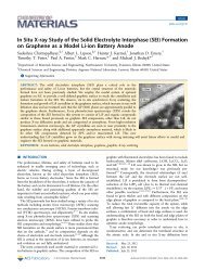
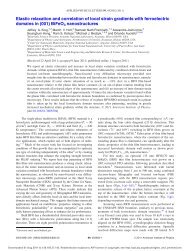
ARTICLES Cote et al. Figure 2. Energy analysis on the flash reduction <strong>of</strong> graphite oxide. (a) The closeup <strong>of</strong> the DSC data (inset) shows the heating curve <strong>of</strong> GO up to 100 °C. The total energy input can be calculated from the area under the heating curve. It took about 377 J/g (i.e., 70 mJ/cm 2 ) <strong>of</strong> thermal energy to heat up the GO film from room temperature. (b) UV/vis spectrum <strong>of</strong> a 1 μm thick GO film. The average absorption over the visible range (400-800 nm) is 63%. Figure 3. Dry flash lithography <strong>of</strong> GO. Left: A shadow mask defining an exposed area with “N” shape was taped onto a GO film supported by filter paper. Center: The black, N-shaped, r-GO pattern obtained after flash. Right: The exposed area was ablated by higher power flashes, leaving an etched “N” pattern on the film. typical optical absorption <strong>of</strong> a 1 μm thick GO film is about 63% in the visible range, the total absorbed energy is about 630 mJ/cm 2 . Using differential scanning calorimetry (DSC), the total thermal energy required to heat a 1 μm thick GO to 100 °C is calculated to be about 70 mJ/cm 2 . Note that this value already includes the extra energy needed to heat <strong>and</strong> evaporate the 15% water in the GO film. Therefore, a single camera flash at this distance can provide 9 times the thermal energy needed for heating GO over 100 °C, which should be more than enough to induce deoxygenating reactions. This suggests that flash irradiation could lead to a much higher degree <strong>of</strong> reduction <strong>of</strong> GO if the photothermal conversion <strong>and</strong> heat absorption by GO are optimized. It was also found that much lower energy flashes (
<strong>Flash</strong> <strong>Reduction</strong> <strong>and</strong> <strong>Patterning</strong> <strong>of</strong> <strong>Graphite</strong> <strong>Oxide</strong> ARTICLES Figure 5. Scalable production <strong>of</strong> functional r-GO based devices on flexible substrates by flash patterning. (a) Arrays <strong>of</strong> r-GO/polystyrene interdigitated electrodes (IDE) were fabricated on a 1.5 in. diameter GO/polystyrene thin film deposited on a Nylon filter paper. The inset shows the close up view <strong>of</strong> one set <strong>of</strong> such IDE. The contact pads are 5 mm × 5 mm. The electrode fingers are 100 μm wide. As a pro<strong>of</strong> <strong>of</strong> concept, the graphene IDEs were used to construct ammonia sensors with polyaniline as the selective layer. The response from such a metal-free, flexible sensor device on exposure to 100 ppm <strong>of</strong> ammonia vapor is shown in b. well processable in water <strong>and</strong> alcohols because <strong>of</strong> the strong electrostatic repulsion between the single layers. 8,16 But r-GO tends to agglomerate in solution because <strong>of</strong> π-π stacking, greatly limiting the concentration <strong>of</strong> single layer solutions. For making an r-GO/polymer composite, it would be ideal to make a GO/polymer blend first to take full advantage <strong>of</strong> the excellent processability <strong>of</strong> GO. r-GO/polymer composites with near arbitrary loading levels can be rapidly fabricated by flash reduction from a blend <strong>of</strong> GO <strong>and</strong> polymer particles. An additional advantage is that the excess heat generated can be utilized to induce welding between the polymer <strong>and</strong> the r-GO sheets. A pro<strong>of</strong>-<strong>of</strong>-concept experiment was shown in Figure 4 where GO is flash-reduced <strong>and</strong> welded with polystyrene beads. First, GO single layers <strong>and</strong> polystyrene colloids were mixed in water with a predetermined fraction. Then films <strong>of</strong> a GO/ polystyrene mixture were made by filtration. Such thin “filter cakes”, if detached from the filter paper, were brittle <strong>and</strong> cracked easily upon manipulation as shown in the low magnification SEM image (Figure 4a <strong>and</strong> 4b, inset). The SEM image also revealed a r<strong>and</strong>om blend <strong>of</strong> polystyrene beads with GO (Figure 4a). After flash irradiation, GO was reduced <strong>and</strong> the polystyrene particles <strong>and</strong> GO were fused together, leading to a continuous, conducting film (Figure 4b <strong>and</strong> inset). The deformation <strong>of</strong> polymer colloids can be clearly observed in the TEM images, where the polymer particles were deliberately s<strong>and</strong>wiched between two GO thin films using layer by layer deposition (Figure 4c). The spreading <strong>of</strong> molten polystyrene on the r-GO sheets was evident after flashing (Figure 4d). The thickness <strong>of</strong> each GO film is estimated to be no more than 35 nm based on the widths <strong>of</strong> the folds. <strong>Flash</strong> irradiation on these thin films was able to generate sufficient heat to s<strong>of</strong>ten the polystyrene beads. Without GO, flash irradiation had little effect on the colloids (see Supporting Information, Figure S2) since polystyrene is transparent in the visible range. In the GO/polystyrene films, the polymer particles can act as a heat sink to drain away the excess heat to avoid overexposure during patterning. This helps to improve the resolution <strong>of</strong> the patterns <strong>and</strong> the integrity <strong>of</strong> the reduced domains. Because many properties <strong>of</strong> GO are altered after reduction such as color, electrical conductivity, thermal stability, surface energy, wettability <strong>and</strong> chemical reactivity, flash reduction, <strong>and</strong> patterning <strong>of</strong> GO is especially promising for fabricating functional surfaces <strong>and</strong> devices. For example, Figure 5a shows arrays <strong>of</strong> interdigitated r-GO/polystyrene electrodes fabricated on a flexible, 1.5 in. Nylon “wafer” upon flashing through a mask printed on a sheet <strong>of</strong> overhead transparency. A GO/ polystyrene blend was used as the precursor to improve the resolution <strong>and</strong> mechanical durability <strong>of</strong> the patterned films. The exposed areas became conducting with the sheet resistance decreased significantly from 2 × 10 8 Ω/ to 9.5 kΩ/square. The flashed areas also became more hydrophobic. Such electrodes were used to construct chemical vapor sensors by depositing some conducting polymer polyaniline nan<strong>of</strong>ibers. When exposed to 100 ppm NH 3 vapor, such all-organic, flexible sensors showed comparable sensitivity (Figure 5b) <strong>and</strong> time response (see Supporting Information, Figure S3) to those made with conventional metal electrodes <strong>and</strong> hard substrates. 27 The wettability contrast between the electrode fingers <strong>and</strong> the blank areas may be further utilized to fabricate micr<strong>of</strong>luidic or electrowetting devices. Advancement in the processing technique can usually bring breakthroughs <strong>and</strong> discoveries in the materials as seen in the development <strong>of</strong> carbon nanotubes 28-30 <strong>and</strong> conducting polymers. 31 Some inspiring results have been reported on flash treatment <strong>of</strong> nanomaterials such as single-walled carbon nanotubes, Si nanowires, <strong>and</strong> conducting polymer nan<strong>of</strong>ibers. 32-34 However, in all these cases it caused the degradation <strong>of</strong> electrical conductivity. <strong>Flash</strong> irradiation <strong>of</strong> GO makes an insulating material conducting, enhancing its electrical conductivity by many orders <strong>of</strong> magnitude. Therefore, it could lead to many more useful applications. Compared to chemical <strong>and</strong> high temperature thermal treatments, flash reduction is rapid, chemical-free, <strong>and</strong> energy efficient. It could be an enabling technique that holds great promise for patterning GO films in device <strong>and</strong> composite applications. Acknowledgment. We thank the National Science Foundation (SGER CMMI-0853573) for supporting this work. L.J.C. gratefully (27) <strong>Huang</strong>, J. X.; Virji, S.; Weiller, B. H.; Kaner, R. B. J. Am. Chem. Soc. 2003, 125, 314–315. (28) Banerjee, S.; Hemraj-Benny, T.; Wong, S. S. AdV. Mater. 2005, 17, 17–29. (29) Liu, J.; Fan, S. S.; Dai, H. J. MRS Bull. 2004, 29, 244–250. (30) Sun, Y. P.; Fu, K. F.; Lin, Y.; <strong>Huang</strong>, W. J. Acc. Chem. Res. 2002, 35, 1096–1104. (31) Skotheim, T. A.; Reynolds, J. R. H<strong>and</strong>book <strong>of</strong> conducting polymers, 3rd ed.; CRC: London, 2007. (32) Ajayan, P. M.; Terrones, M.; de la Guardia, A.; Huc, V.; Grobert, N.; Wei, B. Q.; Lezec, H.; Ramanath, G.; Ebbesen, T. W. Science 2002, 296, 705–705. (33) Wang, N.; Yao, B. D.; Chan, Y. F.; Zhang, X. Y. Nano Lett. 2003, 3, 475–477. (34) <strong>Huang</strong>, J. X.; Kaner, R. B. Nat. Mater. 2004, 3, 783–786. J. AM. CHEM. SOC. 9 VOL. 131, NO. 31, 2009 11031