Operating and installation instructions EWFS Plug ... - Warema
Operating and installation instructions EWFS Plug ... - Warema
Operating and installation instructions EWFS Plug ... - Warema

Create successful ePaper yourself
Turn your PDF publications into a flip-book with our unique Google optimized e-Paper software.
<strong>Operating</strong> <strong>and</strong> <strong>installation</strong> <strong>instructions</strong><br />
<strong>EWFS</strong> <strong>Plug</strong> receiver PL/FZL<br />
Keep for future use!<br />
Valid from 21 June 2011<br />
General information<br />
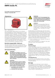
Fig. 1 <strong>EWFS</strong> <strong>Plug</strong> receiver<br />
The <strong>EWFS</strong> <strong>Plug</strong> receivers enable the simple <strong>and</strong> cost-effective<br />
retrofitting of a wireless remote control for sun shade drives.<br />
Absolutely no electrical <strong>installation</strong> work is required for this.<br />
The plug receivers can receive move comm<strong>and</strong>s from <strong>EWFS</strong>compatible<br />
transmitters, such as <strong>EWFS</strong> H<strong>and</strong>-held transmitters,<br />
<strong>EWFS</strong> Timers or <strong>EWFS</strong> Weather stations, <strong>and</strong> are available<br />
with two different operating modes: permanent mode<br />
(PL) <strong>and</strong> radio time mode (FZL).<br />
Intended use<br />
The device was developed to control sun shading systems.<br />
The approval of the manufacturer must be obtained for uses<br />
outside of the purposes listed in these <strong>instructions</strong>.<br />
Safety <strong>instructions</strong><br />
W WARNIN<br />
The electrical <strong>installation</strong> must be performed<br />
by a certified electrician in accordance with<br />
the electrical <strong>installation</strong> regulations published<br />
by the Association of German Electrical<br />
Engineers (VDE 0100) or the st<strong>and</strong>ards<br />
<strong>and</strong> regulations of the country in which the<br />
device is being installed. The electrician must<br />
observe the <strong>installation</strong> <strong>instructions</strong> included<br />
with the electrical device.<br />
W WARNIN<br />
If hazard-free operation cannot be assumed,<br />
the device may not be started or must be<br />
deactivated. This assumption is justified if<br />
The housing or the supply lines show signs<br />
of damage<br />
The device is no longer working.<br />
W WARNIN<br />
Switch off the supply voltage of the <strong>EWFS</strong> <strong>Plug</strong><br />
receiver when you perform activities on products<br />
connected to the plug receiver. Danger due<br />
to sudden movements of the equipment or electric<br />
shock.<br />
C CAUTIO<br />
Never activate buttons on your transmitter arbitrarily<br />
without visual contact to the sun shading<br />
product. Children may not play with this product<br />
- remote controls or transmitters must not<br />
get into the h<strong>and</strong>s of children!<br />
The range of radio controls is restricted by legal regulations<br />
for radio systems <strong>and</strong> through structural factors. Adequate<br />
radio reception must be ensured when planning the project.<br />
This applies especially if the radio signal must penetrate<br />
through walls <strong>and</strong> ceilings. The control unit should not be<br />
installed in the immediate vicinity of metal components (steel<br />
beams, steel-reinforced concrete, fire door).<br />
n Therefore, check that the receiver is functioning properly<br />
before the final <strong>installation</strong>.<br />
Strong local transmitter systems (e.g. baby monitors or neighbouring<br />
transmitters) can interfere with the reception.<br />
Installation<br />
n First switch off the mains supply at the upstream fuse.<br />
n Locate the plug-in connector for the electric drive, release<br />
the safety catch <strong>and</strong> disconnect the connector <strong>and</strong> plug.<br />
Next, connect these to the <strong>EWFS</strong> <strong>Plug</strong> receiver <strong>and</strong> lock<br />
the plug-in connection with the safety catch.<br />
n The <strong>EWFS</strong> <strong>Plug</strong> receiver must not be subjected to direct<br />
sunlight. Route the cable in such a way that water cannot<br />
flow along the cable into the device. The <strong>EWFS</strong> <strong>Plug</strong><br />
receiver must be mounted securely (jolt-free mounting).<br />
If several <strong>EWFS</strong> <strong>Plug</strong> receivers are in use, they must be<br />
mounted a minimum distance of 0.5 m apart.<br />
n When mounting the plug receiver behind a metal panel:<br />
Mount the plug receiver such that the side of the housing with<br />
the printed radio waves symbol faces the opening of the<br />
panel. This ensures the best possible radio reception.<br />
Special mounting housings in different colours are available<br />
for protection from the weather <strong>and</strong> for discrete <strong>installation</strong> of<br />
the <strong>EWFS</strong> <strong>Plug</strong> receiver on the facade.<br />
Note: The <strong>EWFS</strong> <strong>Plug</strong> receiver does not fit into the mounting<br />
housings with article numbers 317 381, 317 382 <strong>and</strong><br />
317 383 because of its larger dimensions.<br />
Information on the electrical connection<br />
The device meets the EMC guidelines for use in residential<br />
<strong>and</strong> commercial areas.<br />
Commissioning<br />
n After the device is connected, the manually operated<br />
switch, if present, must be permanently set to the UP position<br />
<strong>and</strong> kept there. If you select a different position, the<br />
power supply to the device will be interrupted, preventing<br />
your sun shading product from being moved in high<br />
winds. After retrofitting, the switch can no longer be used<br />
to operate the equipment. Therefore, have your electrician<br />
electrically bridge the snap-in switch.<br />
n Switch the mains supply back on. The device is then<br />
ready to operate.<br />
890517_a•en•22.06.2011 We reserve the right to carry out improvements 1
Function<br />
<strong>EWFS</strong> <strong>Plug</strong> receiver PL (permanent mode):<br />
This operating mode is useful for fabric products <strong>and</strong> roller<br />
shutters: The sun shading product responds to the operation<br />
of the UP or DOWN button on the transmitter by moving in<br />
the corresponding direction <strong>and</strong> immediately goes into lock<br />
mode. The button may be released immediately <strong>and</strong> the sun<br />
shading system will move until the fixed run time of 3 minutes<br />
has expired. To release the lock <strong>and</strong> stop the motor, the button<br />
for the opposite direction of movement or the stop button<br />
must be pressed briefly.<br />
<strong>EWFS</strong> <strong>Plug</strong> receiver FZL (radio time logic):<br />
This mode is useful for slat products: By briefly activating (approx.<br />
0.6 seconds) the UP or DOWN button on the transmitter,<br />
you can adjust the sun shading product in small steps.<br />
This function can be used with slat products to tilt the slats.<br />
If the button continues to be activated, the radio time mode<br />
switches to the lock mode. The button may then be released.<br />
The sun shading system moves until the fixed run time of<br />
three minutes has expired. To release the lock <strong>and</strong> stop the<br />
motor, the button for the opposite direction of movement or<br />
the stop button must be pressed briefly.<br />
Symbols used<br />
When the receiver is delivered, it does not "know" any transmitters<br />
initially <strong>and</strong> first needs to learn to which transmitters<br />
it should respond. We refer to this process as "learning".<br />
Explanation of symbols:<br />
Power-up: To learn, you must electrically isolate<br />
a receiver or a group of receivers, either at<br />
the in-line circuit breaker or at the associated<br />
plug-in connector, <strong>and</strong> then reconnect it again<br />
after approx. 5 seconds. (Power-up procedure).<br />
Always carry out a power-up procedure when<br />
you see the symbol of the circuit breaker.<br />
The receiver is now in learn mode for approx.<br />
one minute. The learn button on the transmitter<br />
must be pushed within this period or the<br />
learning mode is closed. Push the learn button<br />
on your transmitter whenever you see the learn<br />
button symbol.<br />
Wave: After the learn button on the transmitter<br />
is activated, the connected sun shading system<br />
carries out several movements. In these <strong>instructions</strong>,<br />
we use the adjacent symbol for waving.<br />
Waving once: Press the learn button on the<br />
transmitter, wait until the connected sun shading<br />
system moves <strong>and</strong> then release the button<br />
immediately.<br />
Learning in the master channel<br />
You can either learn in a 1-channel transmitter or one channel<br />
of an 8-channel transmitter in a receiver as the master channel.<br />
With an 8-channel transmitter, you only need to make<br />
sure that you first select the desired channel, as the following<br />
example shows:<br />
How to learn channel 1 of an 8-channel h<strong>and</strong>-held<br />
transmitter into a receiver:<br />
1<br />
2<br />
Ι<br />
We reserve the right to carry out improvements<br />
Place the receiver into learn<br />
mode: Perform the power-up<br />
procedure on the receiver.<br />
Learn in the transmitter:<br />
Take the transmitter, select<br />
channel 1, push <strong>and</strong> hold the<br />
learn button, the sun shading<br />
waves once, release the<br />
button.<br />
Result: You can now operate the receiver with channel 1 of<br />
the transmitter.<br />
Forming a group<br />
You would like to operate two external venetian blinds with an<br />
8-channel h<strong>and</strong>-held transmitter (I) as follows:<br />
Channel 1 controls external venetian blind 1 (master channel)<br />
Channel 2 controls external venetian blind 2 (master channel)<br />
Channel 3 controls both external venetian blinds together<br />
(auxiliary channel)<br />
1<br />
1<br />
2<br />
1 2<br />
2<br />
3<br />
Ι Ι Ι<br />
= Master channel = Auxiliary channel<br />
Fig. 2 Forming a group<br />
1st step: Learn in the master channel<br />
One master channel must be learned into each receiver before<br />
you can form a group. As described in the section "Learning<br />
in the master channel", learn in channel 1 on receiver 1<br />
as a master channel <strong>and</strong> channel 2 on receiver 2 as a master<br />
channel.<br />
Note: If this is not possible because the power-up procedure<br />
cannot be performed separately for the receivers,<br />
the master channels must be learned in by means of<br />
"patent learning". Information on this procedure can<br />
be found in the "<strong>EWFS</strong> in practice" brochure at http://<br />
www.warema.de Products Control Systems <strong>EWFS</strong>.<br />
2nd step: Learn in the auxiliary channel<br />
You can now operate the external venetian blinds separately,<br />
<strong>and</strong> each learned channel is a master channel in the respective<br />
receiver. If the learn button is pushed with this master<br />
channel, the learn mode can be started <strong>and</strong> an auxiliary<br />
channel learned into the respective receiver even without the<br />
power-up procedure. If the same auxiliary channel, e.g. channel<br />
3, is now learned into each receiver, both external venetian<br />
blinds can later be operated as a group with channel 3 but<br />
they can still be operated separately via the master channels<br />
1 <strong>and</strong> 2. The next step is to learn the auxiliary channels:<br />
Learning channel 3 into external venetian blind 1<br />
1<br />
Place receiver 1 into learn<br />
mode: Select channel 1, press<br />
Ι<br />
<strong>and</strong> hold the learn button, external<br />
venetian blind 1 waves<br />
once, release the button.<br />
3<br />
1<br />
Ι<br />
Ι<br />
¸<br />
Learn channel 3 as an auxiliary<br />
channel: Select channel<br />
3. Press <strong>and</strong> hold the<br />
learn button, external venetian<br />
blind 1 waves once, release<br />
the button. Channel 3 is now<br />
an auxiliary channel for external<br />
venetian blind 1.<br />
End the learn mode: Select<br />
channel 1 <strong>and</strong> press the UP<br />
or DOWN button.<br />
Result: External venetian blind 1 now can also be operated<br />
with channel 3.<br />
Learning channel 3 into external venetian blind 2<br />
Place receiver 2 into learn<br />
2<br />
mode: Select channel 2, press<br />
Ι<br />
<strong>and</strong> hold the learn button, external<br />
venetian blind 2 waves<br />
once, release the button.<br />
3<br />
Ι<br />
Learn channel 3 as an auxiliary<br />
channel: Select channel<br />
3, press <strong>and</strong> hold the<br />
learn button, external venetian<br />
blind 2 waves once, release<br />
the button. Channel 3 is now<br />
an auxiliary channel for external<br />
venetian blind 2.<br />
890517_a•en•22.06.2011
2<br />
Ι<br />
890517_a•en•22.06.2011<br />
End the learn mode: Select<br />
channel 2 <strong>and</strong> press the UP<br />
or DOWN button.<br />
Result: External venetian blind 2 now can also be operated<br />
with channel 3.<br />
Deleting an auxiliary channel<br />
You can delete all auxiliary channels learned into the receiver<br />
if you have committed an error <strong>and</strong> you want to start over<br />
again. Note the following example:<br />
1<br />
1<br />
2<br />
¸<br />
1 2<br />
2<br />
3<br />
Ι Ι Ι<br />
= Master channel = Auxiliary channel<br />
Fig. 3 Auxiliary channels in receiver 1 <strong>and</strong> 2 are to be deleted.<br />
n Carry out the following steps consecutively with the respective<br />
master channel:<br />
1<br />
1<br />
2<br />
2<br />
Ι<br />
Ι<br />
Ι<br />
Ι<br />
¸<br />
¸<br />
Delete all auxiliary channels<br />
in receiver 1: Select master<br />
channel 1, push the learn<br />
button <strong>and</strong> hold it for at least<br />
20 seconds until the external<br />
venetian blind no longer carries<br />
out any movement!<br />
End the procedure: Select<br />
channel 1 <strong>and</strong> press the UP<br />
or DOWN button.<br />
Delete all auxiliary channels<br />
in receiver 2: Select channel<br />
2, push the learn button <strong>and</strong><br />
hold it for at least 20 seconds<br />
until the external venetian<br />
blind no longer carries out any<br />
movement!<br />
End the procedure: Select<br />
master channel 2 <strong>and</strong> push<br />
the UP or DOWN button.<br />
Result: All auxiliary channels in receiver 1 <strong>and</strong> receiver 2<br />
were deleted.<br />
Note: Only one master channel <strong>and</strong> 15 auxiliary channels can<br />
be learned into each receiver. The master channel cannot<br />
be deleted but can only be overwritten with a new<br />
channel. The auxiliary channels are not deleted when<br />
you learn in a new master channel. The weather station<br />
can be learned in as an auxiliary channel.<br />
Special functions<br />
Manifold special functions are additionally possible in WARE-<br />
MA <strong>EWFS</strong>. Should you wish further information, your specialist<br />
dealer will be pleased to give you the application brochure.<br />
The A, B <strong>and</strong> C function buttons<br />
Function button A of the transmitter can be used to switch off<br />
the sun control temporarily if you additionally use the <strong>EWFS</strong><br />
Weather station in your system.<br />
Temporary deactivation of the sun control:<br />
n Press the A button of the transmitter <strong>and</strong> hold until the sun<br />
shading system stops moving. Release the button again.<br />
The sun control is now switched off for 12 hours. After this<br />
period, the sun control is reactivated again automatically.<br />
Activate the sun control again:<br />
n Press <strong>and</strong> hold the A button of the transmitter. Release<br />
the button again when the sun shading system waves. The<br />
sun control is active again. If the automatic system was<br />
already active, nothing changes.<br />
The A, B <strong>and</strong> C buttons of this transmitter have no function.<br />
Maintenance<br />
There are no parts within the device that require maintenance.<br />
Liability<br />
Failure to comply with the product information in these <strong>instructions</strong><br />
<strong>and</strong> use of the device in a manner that contravenes its<br />
intended use <strong>and</strong> purpose may result in the manufacture refusing<br />
to honour warranty claims for product damage. In this<br />
case, liability for consequential harm to persons or damage<br />
to property will also be excluded. Follow also the <strong>instructions</strong><br />
in the operating manual of your sun shading system. The automatic<br />
or manual operation of the sun shading system when<br />
iced over as well as using the sun shading system during<br />
severe weather may cause damage <strong>and</strong> must be prevented<br />
by the user by taking suitable precautions.<br />
Disposal<br />
After its use, the device must be disposed of according to<br />
legal regulations or returned to your local recycling centre!<br />
User information<br />
For use in the following countries:<br />
A, B, D, DK, E, F, FIN, GB, GR, I, IRL, L, NL, P, S, CH, IS, N.<br />
Technical data<br />
<strong>EWFS</strong> <strong>Plug</strong> receiver PL/FZL Min. Typ. Max. Unit<br />
Supply 230 V AC<br />
<strong>Operating</strong> voltage 85 230 265 V AC<br />
Power consumption 1 W<br />
Drive output<br />
Switching capacity at<br />
230 V AC / cosϕ = 0.6<br />
700 VA<br />
HF receiver<br />
Receive frequency<br />
ASK (OOK)<br />
433.92 MHz<br />
Range<br />
(environment without interference)<br />
30 m<br />
Ambient conditions<br />
<strong>Operating</strong> temperature -20 60 °C<br />
Storage temperature -25 70 °C<br />
Humidity<br />
(non-condensing)<br />
10 85 %RH<br />
Enclosure<br />
Dimensions in mm (W x H x D) 136 x 38 x 33<br />
Degree of protection<br />
IP54<br />
Safety class<br />
I<br />
Test st<strong>and</strong>ards<br />
EN 60730-1: 2009, EN 61000-6-3: 2007, EN 61000-6-2: 2006,<br />
EN 300220-3: 2000, EN 301489-3: 2002<br />
Miscellaneous<br />
Automatic operation Type 1<br />
Software class<br />
A<br />
Location of use<br />
Clean ambient conditions<br />
Available at www.warema.de<br />
Conformity declaration<br />
Article numbers<br />
<strong>EWFS</strong> <strong>Plug</strong> receiver PL without<br />
h<strong>and</strong>-held transmitter<br />
<strong>EWFS</strong> <strong>Plug</strong> receiver PL with<br />
1-channel h<strong>and</strong>-held transmitter<br />
<strong>EWFS</strong> <strong>Plug</strong> receiver FZL without<br />
h<strong>and</strong>-held transmitter<br />
<strong>EWFS</strong> <strong>Plug</strong> receiver FZL with<br />
1-channel h<strong>and</strong>-held transmitter<br />
Mounting housing<br />
White,<br />
similar to RAL 9016<br />
Grey,<br />
similar to RAL 9006<br />
Black,<br />
similar to RAL 9011<br />
WAREMA Renkhoff SE<br />
Hans-Wilhelm-Renkhoff-Strasse 2<br />
D-97828 Marktheidenfeld<br />
We reserve the right to carry out improvements<br />
1002 888<br />
1002 916<br />
1002 887<br />
1002 915<br />
317 745<br />
317 748<br />
317 751<br />
3
Troubleshooting<br />
<strong>EWFS</strong> <strong>Plug</strong> receiver PL/FZL<br />
Help with malfunctions<br />
Type of malfunction Possible cause Remedy<br />
Transmission LED of the transmitter does not light up Battery inserted with wrong polarity or depleted Insert batteries correctly, read the operating <strong>instructions</strong>,<br />
insert new batteries<br />
Move comm<strong>and</strong>s of the transmitter are not executed Transmitter has not been learned in Learn the transmitter as described in the <strong>instructions</strong><br />
The wrong channel was selected<br />
Select the correct channel <strong>and</strong> then repeat the move comm<strong>and</strong><br />
Interfering ambient influences<br />
Reduce the transmitter-receiver distance<br />
Receiver is not supplied with line voltage<br />
Switch on the power supply<br />
Move comm<strong>and</strong>s are executed only sporadically Interference through external transmitter Deactivate the external transmitter<br />
(e.g. Babyphone)<br />
There are reinforced concrete covers or walls located between<br />
the transmitter <strong>and</strong> receiver<br />
Reduce the distance to the receiver<br />
1<br />
A<br />
B<br />
C<br />
1<br />
1 2 3<br />
3<br />
2 1<br />
2<br />
3<br />
3 2<br />
A Connector (on-site connection 230 V AC)<br />
B <strong>EWFS</strong> <strong>Plug</strong> receiver<br />
C <strong>Plug</strong> (power consumer connection)<br />
Neutral conductor (blue)<br />
Phase L (black)<br />
Not required (brown)<br />
PE conductor (green-yellow)<br />
A Neutral conductor (blue)<br />
B UP (black)<br />
C DOWN (brown)<br />
EXAMPLE<br />
W WARNUN The on-site fuse protection of<br />
the <strong>EWFS</strong> <strong>Plug</strong> receiver is dimensioned<br />
according to the smallest line cross-section<br />
(upstream or downstream from the<br />
plug receiver).<br />
When using a motor line of type H05RR-F<br />
4G0.75 downstream from the <strong>EWFS</strong> <strong>Plug</strong><br />
receiver, a supply voltage fuse protection of<br />
6 A must be provided on-site.<br />
Fig. 4<br />
<strong>Plug</strong>-in connection<br />
4<br />
We reserve the right to carry out improvements<br />
890517_a•en•22.06.2011