Power Quality Monitoring
Power Quality Monitoring
Power Quality Monitoring

You also want an ePaper? Increase the reach of your titles
YUMPU automatically turns print PDFs into web optimized ePapers that Google loves.
Energie-Messtechnik<br />
<strong>Power</strong> <strong>Quality</strong> <strong>Monitoring</strong><br />
Energie-Management<br />
<strong>Power</strong> Management<br />
Netzqualitäts-Lösungen<br />
<strong>Power</strong> <strong>Quality</strong> Solutions<br />
Software & Zubehör<br />
Software & Accessories<br />
You can find us everywhere.<br />
There must be a reason.<br />
Main catalogue 2010
“<strong>Quality</strong> is never an accident;<br />
it is always the result of intelligent effort.”<br />
John Russkin<br />
▼<br />
UMG 604 power analyser<br />
<br />
<br />
<br />
<br />
Reduce electricity costs<br />
Stabilise production processes<br />
Reliable supply with energy<br />
Reduce maintenance costs
Chapter 01<br />
Company profile 3<br />
3P-strategy 5<br />
An overview of application options 6<br />
Chapter 02<br />
Energy Measurement Technology<br />
<strong>Power</strong> <strong>Quality</strong> <strong>Monitoring</strong> 7<br />
An overview of UMG families 9<br />
UMG 103 – universal measuring instrument for DIN rails 12<br />
UMG 104 – power analyser for DIN rails 18<br />
UMG 604 – power analyser for DIN rails 24<br />
UMG 605 – power quality analyser for DIN rails 32<br />
UMG 96L/UMG96 – universal measuring instrument 96x96mm 38<br />
UMG 96S – universal measuring instrument with M-Bus, Modbus<br />
and Profibus/harmonics display 44<br />
UMG 503 – 144 x 144mm power analyser 52<br />
UMG 505 – power analyser with LON and analogue IOs 60<br />
UMG 507 – power analyser with continuous measurements,<br />
Ethernet and short term interruption detection 68<br />
UMG 508 – multifunctional power analyser 76<br />
UMG 511 – class A power quality analyser in accordance with<br />
IEC61000-4-30 and PQ reports for EN50160/61000-2-4 82<br />
Chapter 03<br />
<strong>Power</strong> Management 89<br />
Electronic impulse-energy meter 92<br />
Peak demand management, UMG 507Emax 100<br />
Data logger, ProData ® 106<br />
Chapter 04<br />
<strong>Power</strong> <strong>Quality</strong> Solutions 111<br />
<strong>Power</strong> factor controller, Prophi ® 114<br />
<strong>Power</strong> capacitors for power factor correction 120<br />
Conventional PFC without reactors (PFC), 124<br />
Detuned power factor correction (PFC),<br />
harmonic filters 130<br />
Dynamic power factor correction (DPFC) 138<br />
Chapter 05<br />
Software 145<br />
GridVis, OPC Server, MS Excel analysis tools 148<br />
Chapter 06<br />
Accessories 161<br />
Current transformer, mechanical accessories, field bus<br />
components, data server, touch panels, ... 164<br />
Chapter 07<br />
Appendix 205<br />
PFC cable diameters, fuses, cos-phi selection table,<br />
project descriptions 206
3<br />
▼<br />
Chapter 1<br />
Janitza electronics ®<br />
The story<br />
Janitza ® electronics GmbH was founded by Mr. Eugen Janitza and<br />
Mr. Markus Janitza in Lahnau in the year 1986. After Eugen<br />
Janitza, one of the co-founders, retired from the company, his<br />
son, Markus Janitza, took over as general manager.<br />
As a medium-sized family company, Janitza electronics ® GmbH<br />
is an important employer in the region with a significant<br />
upwards tendency. The management is dedicated to the site in<br />
Germany which is testified by the continual, active apprentice -<br />
ship schemes for young talents. The complete chain of value<br />
creation including product development, production and sales is<br />
based in Lahnau and the major expansion of production area at<br />
the beginning of 2007 shows that this will continue to be the<br />
case in the future. Traditional values such as continuity and reliability<br />
are of great interest to our customers along with innovative<br />
technology and products together with a rapid, professional<br />
service.<br />
▼
The customers<br />
Janitza electronics ® GmbH products are generally of interest to all<br />
professional consumers of electrical energy. The products from<br />
Janitza electronics ® are already used by 17 companies which are<br />
listed in the German Shares Index (DAX). The most important<br />
customers are in the automobile industry, the banking and insurance<br />
sector or local councils. The products are used in industry,<br />
commercial buildings, by energy suppliers, in airports, supermarkets,<br />
universities and in hospitals. However, the use of our products<br />
is also lucrative for smaller companies.<br />
Janitza electronics ® GmbH has an export ratio of approximately<br />
50% and markets its products in more than 60 countries throughout<br />
the world.<br />
The focus<br />
Janitza electronics ® GmbH is a leading global manufacturer in<br />
the field of digital integrated measuring equipment for energy<br />
distributors, energy optimisation systems and power quality<br />
solutions. The products made by Janitza electronics ® are generally<br />
used to reduce energy, maintenance and products costs.<br />
Awareness of power quality has gained significance in all<br />
companies in the past years. Excessive power quality distortion<br />
lead to increased wear and tear in all electrical supply equipment<br />
and any connected electrical and electronic loads and<br />
can lead even up to production stoppages. Our measuring<br />
instruments therefore provide essential information about<br />
insufficient power quality and hence enable customers to take<br />
measures for the improvement of power quality problems.<br />
This leads to a longer lifespan for equipment and improved<br />
sustainability of the respective investments.<br />
The possibility of allocating energy costs to certain products is<br />
becoming more and more important to industrial companies.<br />
Janitza electronics ® also has customised solutions for cost centre<br />
analysis.<br />
The reduction of expensive peak demand loads and the compensation<br />
of reactive power can immediately cut down the<br />
electricity bill.<br />
Reflow soldering machine in the PQM device production<br />
4
5<br />
▼<br />
Chapter 1<br />
Janitza’s ®<br />
3P-Strategy<br />
Janitza’s ® 3P-Strategy<br />
<strong>Power</strong> <strong>Quality</strong> <strong>Monitoring</strong> - <strong>Power</strong> Management - <strong>Power</strong> <strong>Quality</strong> Solutions<br />
The products, systems and services of Janitza electronics ® range from measurement (collection of data) through energy<br />
management to solutions for the improvement of power quality. Janitza electronics ® does not solely limit itself to the collection<br />
of data but, based on the measurement data, offers customised solutions in the fields of power quality and power management.<br />
This one-stop offer supports the best possible efficiency and power reliability.<br />
<strong>Power</strong> Management<br />
Peak demand management<br />
Collection of data<br />
Cost centre management<br />
Energy efficiency<br />
<strong>Power</strong> <strong>Quality</strong> <strong>Monitoring</strong><br />
Measurement<br />
<strong>Monitoring</strong><br />
Automatic alarm management<br />
Detection of PQ problems<br />
<strong>Power</strong> <strong>Quality</strong> Solutions<br />
<strong>Power</strong> factor correction (PFC)<br />
Harmonic filters<br />
Dynamic PFC<br />
▼
An overview of application options<br />
Switch:<br />
Communication using<br />
TCP/IP, internet<br />
Janitza ® UMG 511:<br />
EN50160 Standard<br />
<strong>Monitoring</strong> of power quality<br />
Class A <strong>Power</strong> <strong>Quality</strong> <strong>Monitoring</strong><br />
Computer environment:<br />
- Programming and assessment software<br />
- Cost centre data collection<br />
- <strong>Power</strong> quality<br />
- Analysis tools<br />
- Database management<br />
- Etc.<br />
Janitza ® UMG 508:<br />
<strong>Monitoring</strong> the reliability of voltage supplies<br />
<strong>Monitoring</strong> short-term interruption<br />
Janitza ® Prophi ® :<br />
Reactive power controller<br />
Janitza ® UMG 604, UMG 503 - 507:<br />
Cost centre analysis, consumer data collection, ...<br />
Janitza ® ProData ® :<br />
Data logger<br />
Janitza ® UMG 507 EMax:<br />
Peak demand management<br />
Janitza ® UMG 103 / UMG 96S:<br />
<strong>Monitoring</strong> important energy and electrical data; replacement for analogue measuring equipment<br />
Fixed & automatic<br />
power factor<br />
correction<br />
Dynamic<br />
power factor<br />
correction<br />
De-tuned<br />
capacitor banks<br />
harmonic filters<br />
Janitza ® <strong>Power</strong> <strong>Quality</strong> Solutions<br />
6
▼<br />
Chapter 2<br />
<strong>Power</strong> <strong>Quality</strong> <strong>Monitoring</strong><br />
UMG 103 Pages 12 - 17<br />
- Universal measuring device for DIN rail mounting without display<br />
- Interface and harmonic measurement up to 25th in current and voltage<br />
New<br />
UMG 104 Pages 18 - 23<br />
- <strong>Power</strong> analyser for DIN rail mounting with display<br />
- Interface and harmonic measurement up to 40th in current and voltage<br />
UMG 604 Pages 24 - 31<br />
- <strong>Power</strong> analyser for DIN rail mounting<br />
- 800 various measurement parameters<br />
- Continuous measurement with recognition of short-term interruptions<br />
- Ethernet, Bacnet, Modbus, Profibus, RS232, RS485<br />
- Extendable up to 7 user programs (graphic programming)<br />
- Peak demand management; accuracy classification 0.5S<br />
New<br />
UMG 605 Pages 32 - 37<br />
- <strong>Power</strong> quality analyser for DIN rail mounting according to<br />
EN50160 and EN61000-2-4<br />
- 2000 various measurement parameters<br />
- THD, flicker, short-term interruptions, transients, unbalanced ...<br />
UMG 96L/UMG 96 Pages 38 - 43<br />
- Digital diversity in comparison to analogue simplicity<br />
- Universal measuring device (96x96mm)<br />
- UMG 96 with pulse outputs/signal output<br />
UMG 96S Pages 44 - 51<br />
- Economic universal measuring device with interface<br />
- 2 digital outputs (as pulse or signal output)<br />
- Profibus/Modbus/M-bus/ harmonic display<br />
- Clock/memory<br />
UMG 503 Pages 52 - 59<br />
- <strong>Power</strong> analyser (144x144mm)<br />
- Extended measurement range, higher accuracy<br />
- Modbus, RS232, RS485, 2 relay outputs,<br />
pulse output, analogue output<br />
UMG 505 Pages 60 - 67<br />
- <strong>Power</strong> analyser (144x144mm)<br />
- LON, Modbus, RS232, RS485<br />
- 5 digital outputs, 4 analogue outputs, 4 digital inputs<br />
UMG 507 Pages 68 - 75<br />
- <strong>Power</strong> analyser (144x144mm)<br />
- Continuous measurement with detection of short-term interruptions<br />
- Ethernet, Modbus, Profibus, RS232, RS485<br />
- 6 digital inputs and outputs, 2 analogue outputs, 1 temperature input<br />
- Peak demand management<br />
New<br />
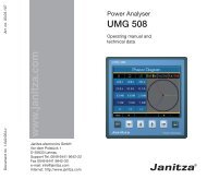
UMG 508 Pages 76 - 81<br />
- <strong>Power</strong> analyser (144x144 mm)<br />
- Continuous measurement with recognition of short-term interruptions<br />
- Ethernet, Modbus, Profibus, RS485<br />
- THD, short-term interruptions, transient, unsymmetrical ...<br />
New<br />
UMG 511 Pages 82 - 88<br />
- Class A power quality analyser according to IEC61000-4-30<br />
<strong>Power</strong> quality reports in line with EN50160 and EN61000-2-4<br />
- Harmonics up to a 63 rd<br />
- THD, flicker, short-term interruptions, transient, unsymmetrical ...<br />
- Including GridVis software with report generator for EN50160<br />
▼<br />
7
PQM - <strong>Power</strong> <strong>Quality</strong> <strong>Monitoring</strong><br />
PQM - <strong>Power</strong> <strong>Quality</strong> <strong>Monitoring</strong><br />
Energy measurement technology<br />
The first step towards saving energy and improving operational processes is the measurement of the<br />
most important parameters of your electrical energy supply while monitoring the peak loads.<br />
Janitza electronics ® offers you a complete range of power<br />
monitoring units with the corresponding accessories.<br />
The UMG measuring equipment and power analysers<br />
help you to gain a comprehensive overview of your<br />
energy supplies and introduce the correct measures.<br />
The power quality is also monitored according to the<br />
general valid standards (e.g. EN50160). The<br />
GridVis software packages in connection with<br />
the measurement equipment and power<br />
analysers from Janitza electronics ® offer<br />
you energy and power monitoring<br />
with real-time diagnosis from the<br />
provider through to all levels of your<br />
enterprise.<br />
8
▼<br />
Chapter 2<br />
Overview of universal measuring instruments<br />
Type<br />
Item number<br />
UMG 103<br />
52.18.001<br />
52.20.001<br />
UMG 104<br />
P<br />
52.20.002<br />
UMG 604<br />
L E P EP<br />
52.16.003<br />
52.16.002<br />
52.16.004<br />
52.16.001<br />
UMG 605<br />
52.16.027<br />
UMG 96L<br />
52.14.001<br />
(52.14.005)<br />
Measurement range L-N, AC<br />
Measurement range L-L, AC<br />
Over voltage category<br />
Operating voltage L-N, AC<br />
Auxiliary voltage<br />
Three phase/four phase<br />
Quadrants<br />
Scan frequency 50/60Hz<br />
Measurement points per sec.<br />
Continuous measurement<br />
Measurements per second<br />
Effective value from periods<br />
50/60Hz<br />
Harmonics V/A<br />
Distortion factor THD-U in %<br />
Distortion factor THD-I in %<br />
Unbalance<br />
Positive/negative/zero system<br />
Current flicker strength<br />
Short/long-term flicker<br />
Transients<br />
Short-term interruptions<br />
Accuracy V, A<br />
Effective energy classification<br />
Operating hour meter<br />
Weekly time switch<br />
Auxiliary input<br />
Digital inputs<br />
Digital/pulse output<br />
Relay outputs<br />
Analogue inputs<br />
Analogue outputs<br />
Temperature input<br />
Integrated logic<br />
Min/max value memory<br />
Memory size<br />
50 - 300V<br />
85 - 520V<br />
300V CAT III<br />
115-240V<br />
-<br />
-/•<br />
4<br />
5,4kHz<br />
5,400<br />
•<br />
5<br />
10/12<br />
1.3 ... 25<br />
•<br />
•<br />
•<br />
•<br />
-<br />
-<br />
-<br />
-<br />
+-0.2%<br />
0.5S<br />
•<br />
-<br />
-<br />
-<br />
-<br />
-<br />
-<br />
-<br />
-<br />
-<br />
•<br />
-<br />
10 - 600Vrms<br />
18 - 1000Vrms<br />
300V CAT III<br />
-<br />
95 - 240V AC; 135 - 340V DC *1<br />
•/•<br />
4<br />
20kHz<br />
20,000<br />
•<br />
5<br />
10/12<br />
1 - 40<br />
•<br />
•<br />
•<br />
•<br />
-<br />
-<br />
-<br />
-<br />
+-0.2%<br />
0.5S<br />
•<br />
-<br />
-<br />
2<br />
2<br />
-<br />
-<br />
-<br />
1<br />
-<br />
•<br />
4MBFlash<br />
10 - 600Vrms<br />
18 - 1000Vrms<br />
300V CAT III<br />
-<br />
95 - 240V AC; 135 - 340V DC *1 95 - 240V AC; 135 - 340V DC *1<br />
•/•<br />
4<br />
20kHz<br />
20,000<br />
•<br />
5<br />
10/12<br />
1 - 40<br />
•<br />
•<br />
•<br />
•<br />
-<br />
-<br />
50µs<br />
•<br />
+-0.2%<br />
0.5S<br />
•<br />
• Jasic ®<br />
-<br />
2<br />
2<br />
-<br />
-<br />
-<br />
1<br />
Jasic ® (7 Prg.)<br />
•<br />
128 MB Flash<br />
10 - 600Vrms<br />
18 - 1000Vrms<br />
300V CAT III<br />
-<br />
•/•<br />
4<br />
20kHz<br />
20,000<br />
•<br />
5<br />
10/12<br />
1 - 63<br />
•<br />
•<br />
•<br />
•<br />
•<br />
•<br />
50µs<br />
•<br />
+-0.2%<br />
0.5S<br />
•<br />
• Jasic ®<br />
-<br />
2<br />
2<br />
-<br />
-<br />
-<br />
1<br />
Jasic ® (7 Prg.)<br />
•<br />
128 MB Flash<br />
50 - 255V, (16 - 80V) *1<br />
86 - 442V, (28 - 139V) *1<br />
300V CAT III<br />
196 - 255V, (45 - 80V) *1<br />
-<br />
-/•<br />
4 *4<br />
2.5/3kHz<br />
50<br />
-<br />
1<br />
1/1<br />
-<br />
-<br />
-<br />
-<br />
-<br />
-<br />
-<br />
-<br />
-<br />
+-1%<br />
2<br />
•<br />
-<br />
-<br />
-<br />
-<br />
-<br />
-<br />
-<br />
-<br />
-<br />
•<br />
-<br />
▼<br />
Number of storage values<br />
-<br />
156k<br />
5,000k<br />
5,000k<br />
-<br />
9<br />
Clock<br />
Bi-metallic function A/kW<br />
Fault recording function<br />
Peak demand management<br />
Software<br />
Interfaces<br />
RS 232<br />
RS 485<br />
Profibus DP<br />
M-Bus<br />
LON<br />
Ethernet<br />
Web server / e-mail<br />
Protocols<br />
Modbus RTU<br />
ISDN router<br />
Modbus gateway<br />
Profibus DP V0<br />
LonTalk<br />
Modbus TCP/IP,<br />
Modbus over TCP<br />
BACnet IP/MSTP<br />
Catalogue page<br />
-<br />
•<br />
-<br />
-<br />
GridVis<br />
-<br />
•<br />
-<br />
-<br />
-<br />
-<br />
-<br />
•<br />
-<br />
-<br />
-<br />
-<br />
-<br />
-<br />
12<br />
•<br />
•<br />
•<br />
-<br />
GridVis<br />
• •<br />
• •<br />
- •<br />
- -<br />
- -<br />
- -<br />
- -<br />
• •<br />
- -<br />
- -<br />
- •<br />
- -<br />
- -<br />
- -<br />
18<br />
•<br />
•<br />
•<br />
•<br />
GridVis<br />
• • • •<br />
• • • •<br />
- - • •<br />
- - - -<br />
- - - -<br />
- • - •<br />
- •/• - •/•<br />
• • • •<br />
- • - •<br />
- • - •<br />
- - • •<br />
- - - -<br />
- • - •<br />
-/• •/• -/• •/• *3<br />
24<br />
•<br />
•<br />
•<br />
•<br />
GridVis<br />
*1 Other voltages are available as options<br />
(2) Combination options for inputs and outputs: a) 2 digital outputs, b) 2 digital inputs<br />
c) 2 analogue outputs, d) 1 digital output and 1 analogue output, e) 1 digital output and 1 digital input<br />
•<br />
•<br />
•<br />
-<br />
-<br />
•<br />
•/•<br />
•<br />
•<br />
•<br />
•<br />
-<br />
•<br />
•/• *3<br />
32<br />
-<br />
•<br />
-<br />
-<br />
-<br />
-<br />
-<br />
-<br />
-<br />
-<br />
-<br />
-<br />
-<br />
-<br />
-<br />
-<br />
-<br />
-<br />
-<br />
38
Type<br />
UMG 96<br />
UMG 96S<br />
UMG 508<br />
UMG 511<br />
Item number<br />
52.09.001<br />
(52.09.002)<br />
52.13.001<br />
52.13.005<br />
52.13.009<br />
52.13.017<br />
52.13.013<br />
52.13.021<br />
52.13.025<br />
52.13.040<br />
52.13.029<br />
52.21.001<br />
52.19.001<br />
Measurement range L-N, AC<br />
Measurement range L-L, AC<br />
Over voltage category<br />
Operating voltage L-N, AC<br />
Auxiliary voltage<br />
Three phase/four phase<br />
Quadrants<br />
Scan frequency 50/60Hz<br />
Measurement points per sec.<br />
Continuous measurement<br />
Measurements per second<br />
Effective value from periods<br />
50/60Hz<br />
Harmonics V/A<br />
Distortion factor THD-U in %<br />
Distortion factor THD-I in %<br />
Unbalance<br />
Positive/negative/zero system<br />
Current flicker strength<br />
Short/long-term flicker<br />
Transients<br />
Short-term interruptions<br />
Accuracy V, A<br />
Effective energy classification<br />
Operating hour meter<br />
Weekly time switch<br />
Auxiliary input<br />
Digital inputs<br />
Digital/pulse output<br />
Relay outputs<br />
Analogue inputs<br />
Analogue outputs<br />
Temperature input<br />
Integrated logic<br />
Min/max value memory<br />
Memory size<br />
Number of storage values<br />
Clock<br />
Bi-metallic function A/kW<br />
Fault recording function<br />
Peak demand management<br />
Software<br />
Interfaces<br />
RS 232<br />
RS 485<br />
Profibus DP<br />
M-Bus<br />
LON<br />
Ethernet<br />
Web server / e-mail<br />
Protocols<br />
Modbus RTU<br />
ISDN router<br />
Modbus gateway<br />
Profibus DP V0<br />
LonTalk<br />
Modbus TCP/IP,<br />
Modbus over TCP<br />
BACnet IP/MSTP<br />
Catalogue page<br />
50 - 275V, (49 - 76V) *1<br />
86 - 476V, (85 - 132V) *1<br />
300V CAT III<br />
196 - 275V, (49 - 76V) *1<br />
-<br />
-/•<br />
4 *4<br />
2.5/3kHz<br />
50<br />
-<br />
1<br />
1/1<br />
-<br />
-<br />
-<br />
-<br />
-<br />
-<br />
-<br />
-<br />
-<br />
+-1%<br />
2<br />
•<br />
-<br />
-<br />
-<br />
•<br />
-<br />
-<br />
-<br />
-<br />
Comparator<br />
•<br />
-<br />
-<br />
-<br />
•<br />
-<br />
-<br />
-<br />
-<br />
-<br />
-<br />
-<br />
-<br />
-<br />
-<br />
-<br />
-<br />
-<br />
-<br />
-<br />
-<br />
-<br />
38<br />
50 - 300V ( 25 - 150V) *1<br />
87 - 520V<br />
300V CAT III<br />
85-300V(5213025/35; 140 -300V) -<br />
nur 52.13.029; 18 - 70V DC, 18 - 33V AC<br />
-/•<br />
4<br />
1.5kHz<br />
180<br />
-<br />
1<br />
6/6<br />
1.3 ... 15<br />
•<br />
•<br />
-<br />
-<br />
-<br />
-<br />
-<br />
-<br />
+-0.5%<br />
1<br />
•<br />
-<br />
-<br />
- - - - - (2) (2) (2) (2)<br />
2 2 2 2 2 (2) (2) (2) (2)<br />
-<br />
-<br />
- - - (2) (2) - - - -<br />
-<br />
Comparator<br />
•<br />
- -<br />
- -<br />
512k<br />
512k<br />
160k<br />
160k<br />
- - - - -<br />
- - - - -<br />
- - • • - - - - -<br />
•<br />
-<br />
-<br />
GridVis<br />
- •<br />
• -<br />
- • - •<br />
- - • -<br />
-<br />
-<br />
-<br />
•<br />
-<br />
-<br />
- - - - - - • - •<br />
-<br />
-<br />
-<br />
44<br />
10 - 600V<br />
18 - 1000V<br />
600V CAT III<br />
-<br />
95 - 240V AC; 135 - 340V DC<br />
•/•<br />
4<br />
20kHz<br />
20,000<br />
•<br />
5<br />
10/12<br />
1 - 40<br />
•<br />
•<br />
•<br />
•<br />
-<br />
-<br />
50µs<br />
•<br />
+-0.1%<br />
0.2S<br />
•<br />
•<br />
-<br />
8<br />
5<br />
-<br />
-<br />
-<br />
-<br />
• Jasic ®<br />
•<br />
256MB<br />
10,000k<br />
•<br />
•<br />
•<br />
•<br />
GridVis<br />
-<br />
•<br />
•<br />
-<br />
-<br />
•<br />
•/•<br />
•<br />
•<br />
•<br />
•<br />
-<br />
•<br />
•/• *3<br />
76<br />
10 - 600V<br />
18 - 1000V<br />
600V CAT III<br />
-<br />
95 - 240V AC; 135 - 340V DC<br />
•/•<br />
4<br />
20kHz<br />
20,000<br />
•<br />
5<br />
10/12<br />
1 - 63<br />
•<br />
•<br />
•<br />
•<br />
•<br />
•<br />
50µs<br />
•<br />
+-0.1%<br />
0.2S<br />
•<br />
•<br />
-<br />
8<br />
5<br />
-<br />
-<br />
-<br />
-<br />
• Jasic ®<br />
•<br />
256MB<br />
10,000k<br />
•<br />
•<br />
•<br />
•<br />
GridVis<br />
-<br />
•<br />
•<br />
-<br />
-<br />
•<br />
•/•<br />
•<br />
•<br />
•<br />
•<br />
-<br />
•<br />
•/• *3<br />
82<br />
*3 Option *4 Not for effective and reactive power<br />
: Included<br />
- : Not included<br />
10
11<br />
▼<br />
Chapter 2<br />
Overview of universal measuring instruments<br />
Type<br />
Item number<br />
UMG 503<br />
L LG LS S OV V<br />
52.07.017<br />
52.07.027<br />
52.07.028<br />
52.07.008<br />
52.07.006<br />
52.07.001<br />
UMG 505<br />
MOD MOD LON LON<br />
52.10.004<br />
52.10.007<br />
52.10.001<br />
52.10.013<br />
UMG 507<br />
L EL AD P E EP<br />
52.15.004<br />
52.15.021<br />
52.15.003<br />
52.15.002<br />
52.15.001<br />
52.15.005<br />
Measurement range L-N, AC<br />
Measurement range L-L, AC<br />
Over voltage category<br />
Operating voltage L-N, AC<br />
Auxiliary voltage<br />
Three phase/four phase<br />
Quadrants<br />
Scan frequency 50/60Hz<br />
Measurement points per sec.<br />
Continuous measurement<br />
Measurements per second<br />
Effective value from periods<br />
50/60Hz<br />
Harmonics V/A<br />
Distortion factor THD-U in %<br />
Distortion factor THD-I in %<br />
Unbalance<br />
Positive/negative/zero system<br />
Current flicker strength<br />
Short/long-term flicker<br />
Transients<br />
Short-term interruptions<br />
Accuracy V, A<br />
Effective energy classification<br />
Operating hour meter<br />
Weekly time switch<br />
Auxiliary input<br />
Digital inputs<br />
Digital/pulse output<br />
Relay outputs<br />
Analogue inputs<br />
Analogue outputs<br />
Temperature input<br />
Integrated logic<br />
Min/max value memory<br />
Memory size<br />
50 - 500V<br />
80 - 870V<br />
600V CAT III<br />
-<br />
85 - 265V AC; 80 - 370V DC *1<br />
•/•<br />
4<br />
6.4/7.68kHz<br />
256<br />
-<br />
2<br />
2/2<br />
1 - 20<br />
•<br />
•<br />
-<br />
-<br />
-<br />
-<br />
-<br />
-<br />
+-0.2%<br />
1<br />
-<br />
-<br />
- - - - 1 *3 1<br />
- - - - - -<br />
- - - - 1 *3 •<br />
- - - - 2 *3 2<br />
- - - - - -<br />
- - - - 1 *3 1<br />
-<br />
Comparator<br />
•<br />
128k<br />
512k<br />
128k<br />
128k<br />
512k<br />
512k<br />
50 - 500V<br />
80 - 870V<br />
600V CAT III<br />
-<br />
85 - 265V AC; 80 - 370V DC *1<br />
•/•<br />
4<br />
6.4/7.68kHz<br />
256<br />
-<br />
2<br />
2/2<br />
1 - 20<br />
•<br />
•<br />
-<br />
-<br />
-<br />
-<br />
-<br />
-<br />
+-0.2%<br />
1<br />
-<br />
•<br />
-<br />
4<br />
5<br />
-<br />
-<br />
4<br />
-<br />
Comparator<br />
•<br />
512k<br />
50 - 500V<br />
80 - 870V<br />
600V CAT III<br />
-<br />
85 - 265V AC; 80 - 370V DC *1<br />
•/•<br />
4<br />
1.65/1.98kHz<br />
1,650/1,980<br />
•<br />
5<br />
10/10<br />
1.3 - 15<br />
•<br />
•<br />
•<br />
•<br />
-<br />
-<br />
-<br />
•<br />
+-0.2%<br />
1<br />
•<br />
•<br />
-<br />
6 - 6 6 6 6<br />
6 - 6 6 6 6<br />
- - - - - -<br />
- - 1 1 1 1<br />
- - 2 2 2 2<br />
- - 1 1 1 1<br />
•<br />
•<br />
256k<br />
16MB<br />
256k<br />
256k<br />
16MB<br />
16MB<br />
▼<br />
Number of storage values<br />
80k<br />
320k<br />
80k<br />
80k<br />
320k<br />
320k<br />
320,000<br />
18k<br />
1.000k<br />
18k<br />
18k<br />
1,000k<br />
1,000k<br />
Clock<br />
Bi-metallic function A/kW<br />
Fault recording function<br />
Peak demand management<br />
Software<br />
Interfaces<br />
RS 232<br />
RS 485<br />
Profibus DP<br />
M-Bus<br />
LON<br />
Ethernet<br />
Web server / e-mail<br />
Protocols<br />
Modbus RTU<br />
ISDN router<br />
Modbus gateway<br />
Profibus DP V0<br />
LonTalk<br />
Modbus TCP/IP,<br />
Modbus over TCP<br />
BACnet IP/MSTP<br />
Catalogue page<br />
•<br />
•<br />
-<br />
-<br />
GridVis<br />
• • - - • •<br />
- - • • • •<br />
- - - - - -<br />
-<br />
-<br />
-<br />
-<br />
• • • • • •<br />
- - - - - -<br />
- - - - - -<br />
- - - - - -<br />
- - - - - -<br />
- - - - - -<br />
- - - - - -<br />
52<br />
•<br />
•<br />
-<br />
-<br />
GridVis<br />
• - • -<br />
- • - •<br />
- - - -<br />
- - - -<br />
- - • •<br />
- - - -<br />
-/- -/- -/- -/-<br />
• • • •<br />
- - - -<br />
- - - -<br />
- - - -<br />
- - • •<br />
- - - -<br />
- - - -<br />
60<br />
•<br />
•<br />
•<br />
•<br />
GridVis<br />
• • • • • •<br />
• - • • • •<br />
- - - • - •<br />
- - - - - -<br />
- - - - - -<br />
- • - - • •<br />
- •/• -/- -/- •/• •/•<br />
• • • • • •<br />
- • - - • •<br />
- - - - • •<br />
- - - • - •<br />
- - - - - -<br />
- • - - • •<br />
- - - - - -<br />
68<br />
*1 Other voltages are available<br />
as options<br />
(2) Combination options for inputs<br />
and outputs:<br />
a) 2 digital outputs,<br />
b) 2 digital inputs<br />
c) 2 analogue outputs,<br />
d) 1 digital output and<br />
1 analogue output,<br />
e) 1 digital output and<br />
1 digital input<br />
*4 not for effective and reactive<br />
power<br />
: Included<br />
- : Not included
PQM - <strong>Power</strong> <strong>Quality</strong> <strong>Monitoring</strong><br />
Universal measuring equipment<br />
for DIN rail mounting<br />
Universal measuring devices of the UMG 103 product family are mainly designed for use in low voltage<br />
distribution systems.<br />
UMG 103<br />
The UMG 103 is a measuring instrument with an effective energy class of 0.5S.<br />
<strong>Monitoring</strong> harmonics<br />
In addition to a large quantity of electrical measurement values, the UMG 103 offers a multitude of<br />
additional functions such as the measurement of harmonics, the storage of minimum and maximum<br />
values, operating hour meter, bi-metallic strip function and password protection. The interface and<br />
field bus capabilities (Modbus) enable the communication of measurement data and incorporation<br />
into a comprehensive energy management system.<br />
Areas of application<br />
For measuring and checking electrical parameters in energy distribution systems<br />
Cost centre management solutions for data collection<br />
Limit value monitoring, measurement value generator for building management systems or PLC<br />
12
▼<br />
Chapter 2<br />
Universal measuring instrument<br />
UMG 103 universal measuring device<br />
for DIN rail mounting<br />
The UMG 103 is a very compact universal measuring instrument for<br />
mounting on DIN rails. The compact dimensions even enable installation<br />
in limited spaces such as in installation sub-distribution boards.<br />
Installation and connection costs are significantly reduced by mounting<br />
the instrument on a 35mm DIN rail.<br />
In order to make use of the extensive functions of modern measuring<br />
instruments, the interconnection and central analysis of data plays an<br />
important role. This is the reason for not using a display; two LEDs show<br />
the current operating status. The communication of measurement data<br />
takes place through a very fast RS485/Modbus interface.<br />
The UMG 103 performance level is usually sufficient for sub-measurements<br />
in connection with higher performance power analysers such as the UMG 604 or the UMG 508 applied in more complex<br />
energy management systems. In this case, the UMG 103 serves as data measurement point which takes the measurement data and<br />
passes it on to a higher-level point (master device). Using power analysers such as the UMG 604 with an integrated Modbus/Ethernetgateway<br />
and integrated web server, data are brought onto the Ethernet level or are visualised on the homepage. Some examples of<br />
applications are cost centre management systems in office buildings, monitoring feeders to sub-distribution panels, motor control centres<br />
or in IT and data centres.<br />
▼<br />
Main features<br />
Measurement in TN and TT networks<br />
3 voltage measurement inputs (300V CATIII), 3 current measurement inputs<br />
Continuous scanning of the voltage and current measurement inputs<br />
High measurement accuracy, effective energy class 0.5; U/I, 0.2%<br />
Harmonic analysis up to the 25th order<br />
Including GridVis software<br />
RS 485 (Modbus RTU, slave)<br />
Mounting on 35mm DIN rail<br />
Suitable for integration in installation distribution panels<br />
Applications<br />
The UMG 103 is intended for the measurement and calculation of<br />
electrical parameters such as current, voltage, power, consumption<br />
or harmonics etc. in building installations, on distribution panels,<br />
on circuit breakers and on server racks. The UMG 103 is fixed into<br />
cabinets or small installation distributors in any installation position.<br />
The measurement values can be read out using the serial interface.<br />
The highest, lowest and energy values are recorded every two<br />
seconds in a non-volatile memory. The voltage measurement<br />
inputs are designed for the measurement in low voltage networks<br />
in which nominal voltages up to 300V against ground and<br />
surge voltages up to over voltage category III can occur. The<br />
UMG 103 is mainly suitable for measurements in low voltage<br />
networks because it takes the supply voltage from the measurement<br />
voltage and a voltage converter would be therefore<br />
necessary for HV grids.<br />
13
UMG 103<br />
Communication options<br />
The connection of a UMG 103 to a PC using an interface converter<br />
Interface converter<br />
RS232 / RS485 or<br />
USB / RS485<br />
UMG 103<br />
The connection of several UMG 103’s to a PC using a UMG 604 (with optional Ethernet)<br />
Switch<br />
UMG 604E<br />
Modbus using RS485<br />
UMG 103 UMG 103 UMG 103<br />
14
▼<br />
Chapter 2<br />
Functions and technical data<br />
Overview of product variants<br />
Description Type Operating voltage Item number<br />
Universal measuring device 50/60Hz;<br />
Current transformer: ../1/5A<br />
UMG 103 L-N: 115 ... 240 VAC 52.18.001<br />
Measurement range<br />
Voltage L-N<br />
Voltage L-L<br />
Current (CTs: x/1 and x/5A)<br />
Frequency, mains<br />
50-300 V-AC<br />
85-520 V-AC<br />
0.001...7.5A<br />
45...65 Hz<br />
General technical data<br />
Operating voltage CAT III 110 ...240 V-AC<br />
Scanning rate<br />
5.4 kHz per channel<br />
Quadrants 4<br />
Weight<br />
150g<br />
Dimensions<br />
B=71.5 mm, H=90 mm, T=46 mm<br />
Mounting<br />
35 mm DIN rail<br />
Working temperature -10…+55 °C<br />
Storage temperature -20…+70 °C<br />
Protection class According to EN 60529 IP20<br />
Connectable conductors (U/I)<br />
Single wire, multi-wire, fine-wire<br />
Pin cable lugs, ferrule<br />
0.08-2.5 mm 2<br />
1.5 mm 2<br />
Measurement values<br />
Voltage L1, L2, L3, L1-L2, L2-L3, L1-L3 0.2% rdg + 0.02% rng<br />
Current L1, L2, L3, N calculated 0.2% rdg + 0.02% rng<br />
Effective, reactive and apparent power L1, L2, L3, sum Accuracy ±(0.4% rdg + 0.10% rng)<br />
Cos-phi, power factor<br />
L1, L2, L3, sum<br />
Effective/reactive energy Consumed/inductive Class 0.5S(kWh)<br />
Frequency L1, L2, L3 Accuracy ±0.1% rdg<br />
Average value<br />
Yes<br />
Minimum/maximum value<br />
Yes<br />
Operating hour meter<br />
Yes<br />
<strong>Power</strong> quality<br />
Harmonics 1-25th harmonic order,<br />
uneven Current, voltage, L1, L2, L3 Accuracy: 0.5% rdg + 0.05% rng<br />
Distortion factor THD-U in % L1, L2, L3 Accuracy: 0.5% rdg + 0.05% rng<br />
Distortion factor THD-I in % L1, L2, L3 Accuracy: 0.5% rdg + 0.05% rng<br />
Communication<br />
Interfaces<br />
RS 485 Up to 115.2 kbps Yes<br />
Protocols<br />
Modbus RTU/slave<br />
Yes<br />
15
▼<br />
UMG 103<br />
Typical connection options<br />
UMG 103<br />
Illustration: connection option UMG 103<br />
Illustration: connection example for a voltage<br />
measurement using a voltage transformer (VT)<br />
Illustration: current measurement using a sum current<br />
transformer (CT)<br />
16
▼<br />
▼<br />
Chapter 2<br />
UMG 103<br />
Mounting illustration<br />
Support rail<br />
Dimensional drawings<br />
Illustration: front view<br />
Illustration: side view<br />
17
UMG 104<br />
PQM - <strong>Power</strong> <strong>Quality</strong> <strong>Monitoring</strong><br />
More than just a<br />
Multimeter<br />
The UMG 104 equipped with a 500 MHz DSP (digital signal processor) is a very fast and powerful<br />
power analyser.<br />
The continuous scanning of the 8 channels with 20 kHz per channel allows the recording of all electrical<br />
parameters (more than 800 values), minimum - and maximum - values, and the main power<br />
quality values such as harmonics (up to the 40 th , each phase with the detection of direction).<br />
Based on these data loss of production can be avoided, concepts can be developed, such as the electricity<br />
cost reduction programs, and measures introduced. And finally the improvements can be<br />
monitored and recorded with the UMG 104 as well.<br />
Using modern communication architectures, the acquired data are fed to a central location, in powerful<br />
databases, stored centrally and made available for further processing in an open architecture. The<br />
easy integration into an existing building control system or PLC environment extends the capabilities<br />
of the UMG 104.<br />
Applications:<br />
Replacement of analogue and digital instrumentation<br />
Consumption data collection and analysis (load profiles)<br />
Continuous power quality monitoring<br />
Cost center management, i.e. breakdown of energy costs, e.g. allocation per product<br />
Remote control and monitoring of equipment and processes<br />
Protection of networks<br />
“Sensor” for building management systems or PLC<br />
18
▼<br />
▼<br />
Chapter 2<br />
<strong>Power</strong> analyser<br />
excess value by additional functions<br />
By integration of new functions, the UMG 104<br />
exceeds all limits of digital panel meters:<br />
Multifunctional power meter<br />
kWh-meter, kvarh-meter<br />
Harmonic Analyzer<br />
Supervision of condition<br />
Event writer<br />
Data logger<br />
The UMG 104 can accept up to 4 current and 4 voltage inputs, which allows monitoring of up<br />
to 4 single phase circuits. Potential applications include data centers, office buildings, motor<br />
control centers, etc.<br />
Cost-effective, fast and safe communication<br />
Modbus and Profibus<br />
In many cases the costs for installation and communication (e.g. peripheral<br />
equipment for field buses) exceed those for the respective power meters.<br />
Integration of the UMG 104 in an existing field bus architecture means a fast,<br />
cost-efficient and reliable communication. Additional interfaces enable the integration<br />
of the power analysers into PLC or building automation systems. The use<br />
of open standards offers great flexibility to the user.<br />
RS 485<br />
UMG 104<br />
Easy integration of devices with Ethernet<br />
interface<br />
With the Modbus interface function of UMG 104 you can connect via Modbus<br />
gateways (for example UMG 508, UMG 604, ...) to Ethernet. Each instrument<br />
with a Modbus RTU interface can be connected, if its data format and function<br />
codes correspond. Data can be scaled and labelled.<br />
Example PLC communication with Profibus<br />
or Modbus<br />
UMG 508 UMG 104<br />
RS 485<br />
Highspeed Modbus<br />
The devices of UMG 104 series can transfer data via RS485 interface with a<br />
speed of up to 921.6 kB/s among each other device of this series.<br />
Example<br />
Ethernet gateway<br />
19
▼<br />
▼<br />
UMG 104 overview<br />
Central<br />
Building<br />
Control<br />
System<br />
PLC<br />
Software<br />
Grids<br />
<br />
IT, TN, TT - grids<br />
<br />
3 and 4 wire grids<br />
<br />
up to 4 single phase grids<br />
Interfaces<br />
<br />
RS 232<br />
<br />
RS 485<br />
2 Digital inputs<br />
<br />
Pulse input<br />
<br />
Alarm input logic<br />
<br />
Condition monitoring<br />
<br />
High/ low tariff changeover<br />
2 Digital outputs<br />
<br />
Pulse output kWh/ kvarh<br />
<br />
Switching output<br />
<br />
Limit output<br />
<br />
Logical output<br />
Profibus connection<br />
(optional)<br />
Communication Protocols<br />
<br />
Profibus (DP/V0)<br />
<br />
Modbus (RTU)<br />
Temperature input<br />
PT 100, PT 1000, KTY 83, KTY 84<br />
Accuracy<br />
<br />
Energy: class 0.5S (.../5A)<br />
<br />
Current: 0.2 %<br />
<br />
Voltage: 0.2 %<br />
Memory<br />
<br />
4 MByte Flash<br />
<strong>Power</strong> quality<br />
<br />
Harmonics, 1st- 40th<br />
<br />
THD-U/I<br />
<br />
Unbalance<br />
20
▼<br />
Chapter 2<br />
Functions and technical data<br />
Overview of product variants<br />
Three/four phase power analysers; 50/ 60Hz; current transformer ../1/5A; including GridVis programming and analysis software.<br />
Supply Voltage<br />
Interfaces<br />
95...240 V AC,<br />
135...340 V DC<br />
50...110V AC<br />
50...155V DC<br />
20...55V AC<br />
20...77V DC<br />
4 Voltage and<br />
4 Current inputs<br />
2 Digital inputs<br />
2 Digital outputs<br />
1 Temperature input<br />
RS 232<br />
RS 485<br />
Profibus DP V0<br />
Type<br />
Item no.<br />
- UMG 104 52.20.001<br />
- UMG 104 52.20.003<br />
- UMG 104 52.20.005<br />
UMG 104 P 52.20.002<br />
UMG 104 P 52.20.004<br />
UMG 104 P 52.20.006<br />
- = not possible = included<br />
Features<br />
Memory Measurement data 4 MB<br />
Clock<br />
+/- 1 min per month<br />
Operating hours counter<br />
yes<br />
Tarifs<br />
4 x real energy / 4 x reactive energy<br />
Peripherals<br />
Digital inputs as status or pulse input 2<br />
Digital outputs as switching or pulse output 2<br />
Temperature input PT100, PT1000, KTY83, KTY84 1<br />
Password protection<br />
yes<br />
Software GridVis yes<br />
Communication<br />
Interfaces<br />
RS 232 9.6, 19.2, 38.4, 115.2 kbps yes<br />
RS 485 9.6, 19.2, 38.4, 76.8, 115.2, 921.6 kbps yes<br />
Profibus DP Sub D9-pole up to 12 Mbps yes, variant P<br />
Protocols<br />
Modbus RTU<br />
yes<br />
Profibus DP V0<br />
yes, variant P<br />
21
▼<br />
UMG 104<br />
Technical data<br />
Supply voltage L- N, AC see page 9<br />
Overvoltage class<br />
300 V CATIII<br />
Quadrants 4<br />
Continuous Measurement<br />
yes<br />
Sampling rate, 8 channels per channel 20 kHz<br />
Weight<br />
350 g<br />
Dimensions<br />
W=107.5 mm x D=90 mm x H=82 mm<br />
Mounting according to IEC EN60999-1/ DIN EN 50022 35 mm DIN rail<br />
Working temperature -10…55 °C<br />
Connectable wires (U/I) one wire, more wires, fine stranded wires 0.08 - 2.5 mm²<br />
cable end sleeve<br />
1.5 mm²<br />
Protection class according to EN60529 IP 20<br />
Measuring range<br />
Voltage L-N, AC (without PT)<br />
Voltage L-L, AC (without PT)<br />
Current (Transformer: x/1 und x/5 A)<br />
Frequency of fundamental<br />
Grids<br />
Measurement in grids<br />
10…300 V AC<br />
17…520 V AC<br />
0.005...7.5 A<br />
45 ..65 Hz<br />
IT, TN, TT<br />
1ph, 2ph, 3 ph, 4 ph<br />
up to 4 times 1ph<br />
Measured values<br />
Voltage L1, L2, L3, L4, L1-L2, L2-L3, L1-L3 accuracy ±0.2%<br />
Current L1, L2, L3, L4, Sum L1-L3, Sum L1-L4 accuracy ±0.2%<br />
K-factor L1, L2, L3, L4 yes<br />
Rotating current components Positive/ Negative/ Zero Phase Sequence yes<br />
Real, apparent, reactive power L1, L2, L3, L4, Sum L1-L3, Sum L1-L4 accuracy ±0.4% (EN61557-12)<br />
Cos-phi / power factor L1, L2, L3, L4, Sum L1-L3, Sum L1-L4 yes<br />
Phase angle L1, L2, L3, L4 yes<br />
Real energy (kWh)<br />
Reactive energy (Karh)<br />
L1, L2, L3, L4, Sum L1-L3, Sum L1-L4:<br />
- Consumed real energy (rate 1, rate 2)<br />
- Supplied real energy (rate 1, rate 2)<br />
L1, L2, L3, L4, Sum L1-L3, Sum L1-L4:<br />
- Inductive energy (rate 1, rate 2)<br />
- Capacitive reactive energy<br />
Class 0.5S (…/5 A),<br />
Class 1 (…/1 A)<br />
Class 2<br />
Reactive energy (kVAh) L1, L2, L3, L4, Sum L1-L3, Sum L1-L4 yes<br />
Wave form voltage L1, L2, L3, L4 yes<br />
Frequency of mains<br />
accuracy ±0.01 Hz<br />
Temperature input<br />
accuracy ±1.5% rng<br />
Average values<br />
yes<br />
Minimum and maximum values<br />
yes<br />
<strong>Power</strong> quality<br />
Harmonics, 1st- 40th<br />
Current, voltage, real/reactive power (±)<br />
L1, L2, L3, L4<br />
Distortion factor THD-U in % L1, L2, L3, L4 yes<br />
Distortion factor THD-I in % L1, L2, L3, L4 yes<br />
Unbalance<br />
Positive/ Negative/ Zero Phase Sequence<br />
Inrush-currents 10 ms no<br />
Malfunction writer<br />
Short-term interruptions<br />
accuracy V, I Class 1 (EN61000-4-7)<br />
yes<br />
yes<br />
no<br />
no<br />
22
▼<br />
▼<br />
Chapter 2<br />
UMG 104<br />
Connection diagram UMG 104<br />
Dimensional drawing<br />
front view<br />
side view<br />
90 mm<br />
90 mm<br />
107,5 mm<br />
50 mm<br />
76 mm<br />
82 mm<br />
23
UMG 604<br />
PQM - <strong>Power</strong> <strong>Quality</strong> <strong>Monitoring</strong><br />
High performance power analysers<br />
for DIN rails<br />
High performance power analysers from the UMG 604 product family are suitable for use at all network<br />
levels. The high scanning rate enables a continuous measurement by gathering more than 800<br />
measurement parameters. Due to the very high performance level of the digital signal processor, all<br />
important power quality parameters are recorded e.g. short-term interruptions with fault recorder<br />
function, transients, harmonics up to a 40 th and starting current etc. Extensive communication options<br />
e.g. Ethernet (TCP/IP), BACnet, Modbus, Profibus, RS232, RS485, HTTP, FTP, SMTP, SNTP,<br />
SNMP or DNS… allow affordable and quick integration in the existing communication architecture.<br />
Worldwide access to the embedded web server can be gained through a web browser e.g. for energy<br />
consumption analysis. Programs specific to the user can be created with implemented graphic programming.<br />
It is possible to run 7 user programs simultaneously.<br />
Areas of application<br />
For measuring, monitoring and checking electrical parameters in energy distribution units<br />
Consumption data collection and analysis (cost centre data collection)<br />
For monitoring the power quality (harmonics, short term interruptions, transients,<br />
initial current…)<br />
Measurement value generator for building management systems or PLC<br />
Control tasks e.g. depending upon the achieved measurement values or limit values<br />
Peak demand management (avoidance of costly and dangerous peak loads)<br />
Ethernet gateway for subordinate measurement points<br />
Remote monitoring<br />
24
▼<br />
Chapter 2<br />
<strong>Power</strong> analyser<br />
UMG 604: the extra compact<br />
power analyser<br />
Added value through additional functions<br />
Through the integration of various functions, the UMG 604<br />
power analyser goes far beyond the limits of digital multifunctional<br />
measuring equipment and, therefore, offers the respective added<br />
value. The UMG 604 and the use of state-of-the-art processors<br />
allow to offer a very fast and extremely compact power analyser at<br />
an affordable price. The UMG 604 contains the following functions:<br />
<br />
<br />
<br />
<br />
<br />
<br />
<br />
<br />
<br />
<strong>Power</strong> analyser for electrical energy distribution<br />
(over 800 parameters)<br />
Energy consumption and cost centre data collection<br />
<strong>Monitoring</strong> of power quality<br />
Peak demand management (optional)<br />
PLC function (up to 7 simultaneous freely programmable<br />
programs, graphic programming)<br />
Transient recorder<br />
Event recorder<br />
Data logger<br />
Modbus/Ethernet gateway<br />
▼<br />
Main features<br />
<br />
Continuous measurement<br />
Collection of all relevant power quality parameters (harmonics, short-term interruptions, unbalance ...)<br />
Ethernet and embedded web server<br />
Jasic ® interpreter<br />
Up to 7 user defined programs<br />
GridVis software - full version included in the delivery<br />
Applications<br />
Major increases of energy costs make electrical energy a driving force<br />
in costing. With the UMG 604, you can make the first step towards<br />
better cost efficiency. The precise collection of all energy data and<br />
electrical parameters ensures the necessary amount of transparency in<br />
your energy supplies. Concepts can be developed on the basis of the<br />
data e.g. electricity cost reductions and the introduction of measures.<br />
These targeted improvements can also be monitored and recorded<br />
with the UMG 604.<br />
The UMG 604, equipped with a 500 MHz DSP (digital signal<br />
processor), is a fast and high performing power analyser. The<br />
continuous scanning of eight channels with 20 KHz per channel<br />
enables the collection of all relevant electrical parameters (more<br />
than 800 values), minimum and maximum values, the basic<br />
power quality values such as harmonics (up to the 40 th , each<br />
phase with direction recognition) and short-term interruptions.<br />
Even fast transients (> 50µs) can be safely identified. Using<br />
modern communication processes, the collected data is conducted<br />
to a central location, stored centrally in a high-performance<br />
database and provided for further processing in an open<br />
system. Simple integration in an existing building management<br />
system control or PLC environment expands the areas of application<br />
of the UMG 604.<br />
25
UMG 604<br />
DIN rail mounting (6 units): reduction of<br />
installation costs<br />
Measurement equipment is usually installed in the low voltage<br />
main distribution as an integral measurement instrument for the<br />
switchgear cabinet door. Installation and connection costs are<br />
significantly reduced by the installation of the UMG 604 on a<br />
35mm DIN rail. This means that the panel cut-out and wiring to<br />
the cabinet door is no longer necessary. In order to make use of the<br />
extensive functions of modern measuring equipment, the interconnection<br />
and central analysis of the data plays an important<br />
role. This means that the on-site display generally serves the purpose<br />
of the initialisation and service only.<br />
The decidedly compact UMG 604 is suitable for installation in<br />
low voltage main distribution panels and machines as well as in<br />
installation distribution boards which is particularly of interest for<br />
applications in building services engineering, information technology<br />
and data centres.<br />
Modern communication processes<br />
through the Ethernet: affordable, rapid<br />
and safe communication<br />
The costs for installation and communication (e.g. periphery for field<br />
buses) often surpass the costs of the equipment.<br />
By connecting the equipment to an existing Ethernet system, a fast,<br />
optimally priced and reliable communication system can be developed.<br />
Additional interfaces allow the integration of power analysers in<br />
PLC systems or in central building management systems. The use of<br />
clear standards offers the user a high amount of flexibility.<br />
Modbus gateway: the affordable<br />
connection of units without an<br />
Ethernet interface<br />
With the Modbus gateway function, simple Modbus RTU-units can<br />
be connected to the Ethernet using the UMG 604. For example, the<br />
UMG 604 can be used simultaneously as a gateway for subordinate<br />
measurement points or older units which already exist in the installation.<br />
Each unit with a Modbus RTU interface, where the data format<br />
and function codes match up, can be connected. Data can be marked<br />
and scaled.<br />
High-speed Modbus<br />
The devices of the UMG 604 series can transfer data between the units using the RS485 interface at a speed of up to 921.5 kB/s.<br />
The e-mail and homepage inform you<br />
wherever you are…<br />
Who hasn’t experienced it before You are hardly through the door<br />
and the telephone is already ringing. There are problems in production,<br />
computers are crashing and the energy supplies are lost.<br />
You have direct access to the extremely high performance homepage<br />
of the UMG 604 with a web browser and an IP address. Extensive<br />
information is already available to you on the homepage. Online data<br />
are available together with historical data and graphs recording events.<br />
The homepage can be used to directly convert the rates into costs and<br />
be exported as a csv file or printed. As an alternative, you can let yourself<br />
be informed by e-mail anywhere in the world if your energy supply<br />
becomes overloaded, if short-term interruptions to the voltage<br />
supplies bring your production processes to a standstill or unauthori -<br />
zed harmonics reduce the lifespan of equipment. The application possibilities<br />
are endless.<br />
26
▼<br />
Chapter 2<br />
<strong>Power</strong> analyser<br />
<strong>Power</strong> visualisation software<br />
The data gained from various measurement points must be collected, saved, visualised and made available. The GridVis software contained<br />
in the UMG 604 package allows<br />
Parameterisation and programming of UMG measurement equipment<br />
Visualisation of the measurement values with topological view<br />
Automatic download of the measurement data<br />
Data storage<br />
Online analysis tools<br />
Analysis tools for historic data<br />
Visualisation, topological view<br />
GridVis allows an individually adaptable visualisation of online data. The topological view provides a rapid overview of energy distribution<br />
with the possibility of localising power faults by comparing the individual measurement points and by offering the possibility to check the<br />
defined tolerances at a glance.<br />
Customer specific solutions can be quickly and simply implemented through uploading of graphic documents (standard formats such as<br />
JPG) with circuit diagrams, production lines or construction plans and incorporating the respective measurement units by drag and drop<br />
into their actual locations. Limit value excesses (e.g. THD-U is too high) and the status of inputs and outputs can also be displayed.<br />
Online values and analysis<br />
of historic data<br />
With the graphic line writer function, GridVis enables<br />
rapid online presentation of the selected measurement<br />
values. In this function, the graph is continuously expanded<br />
with new measurement values. For example, load profiles<br />
can be presented through the analysis of historic data<br />
in order to produce exact consumption analysis for optimised<br />
electricity supply contracts. Fault analysis through<br />
the comparison of various parameters can also be achieved<br />
with a few mouse clicks.<br />
Graphic programming<br />
The graphic programming option for user programs is completely<br />
new in the field of digital power analysers. Programs<br />
specific to the application can be created with this method<br />
such as the free programming of inputs and outputs, monitoring<br />
of processes or the issue of reports when defined limit<br />
values are achieved. In addition to the operator-friendly graphic<br />
programming, the user is also free to program the Jasic ®<br />
code directly.<br />
programming language<br />
The Jasic ® programming language offers brand new<br />
opportunities. The user is no longer tied to the functions<br />
which are fixed integrations in the unit; the unit can be<br />
expanded to include more functions. Up to seven of these<br />
freely definable user programs can be processed simultaneously<br />
in the unit.<br />
27
▼<br />
UMG 604<br />
Router PLC Software<br />
Networks<br />
<br />
<br />
<br />
IT, TN, TT networks<br />
3 phase and 4 phase networks<br />
Up to 4 single phase networks<br />
Interfaces<br />
<br />
Ethernet<br />
<br />
RS 232<br />
<br />
RS 485<br />
2 digital inputs<br />
<br />
Pulse input<br />
<br />
Logic input<br />
<br />
Status monitoring<br />
<br />
HT/LT conversion<br />
<br />
Emax (max. demand) resetting<br />
Profibus connection<br />
2 digital outputs<br />
<br />
Pulse output kWh/kvarh<br />
<br />
Switch output<br />
<br />
Limit value output<br />
<br />
Emax output<br />
<br />
Logic output<br />
(can be extended through external I/O<br />
modules – see chapter 6)<br />
Communication<br />
<br />
Profibus (DP/V0)<br />
<br />
Modbus (RTU, UDP, TCP, gateway)<br />
<br />
TCP/IP<br />
<br />
BACnet<br />
<br />
HTTP (freely configurable homepage)<br />
<br />
FTP (file transfer)<br />
<br />
SNMP<br />
<br />
TFTP (automatic configuration)<br />
<br />
NTP (time synchronisation)<br />
<br />
SMTP (e-mail function)<br />
<br />
DHCP<br />
Measurement accuracy<br />
<br />
Class: 0.5S (…/5A) class<br />
<br />
Current: 0.2% rng<br />
<br />
Voltage: 0.2% rng<br />
Temperature<br />
measurement input<br />
PT 100, PT 1000, KTY 83, KTY 84<br />
Memory<br />
<br />
128 MB Flash<br />
<br />
16 MB RAM<br />
<strong>Power</strong> quality<br />
<br />
Harmonics up to 40 th<br />
<br />
Short-term interruptions<br />
<br />
Transient recorder (>50µs)<br />
<br />
Starting current (>10ms)<br />
<br />
Unbalance<br />
<br />
Full wave-effective value<br />
recordings (up to 4.5 min)<br />
Peak demand management<br />
<br />
64 stages for load shedding<br />
programming language<br />
28
▼<br />
Chapter 2<br />
Product variants and technical data<br />
Overview of product variants<br />
Three/four phase power analysers; 50/60Hz; current transformer .../1/5a; including GridVis programming and analysis software<br />
Interfaces<br />
95...240V AC,<br />
135...340V DC<br />
Supply voltage<br />
50...110V AC,<br />
50...155V DC<br />
20...55V AC,<br />
20...77V DC<br />
4 voltage and<br />
4 current inputs<br />
Memory<br />
128 MB Flash<br />
2 digital inputs<br />
2 digital outputs<br />
1 temperature input<br />
- UMG 604 E 52.16.002<br />
UMG 604 EP 52.16.001<br />
- UMG 604 E 52.16.012<br />
UMG 604 EP 52.16.011<br />
- UMG 604 E 52.16.022<br />
UMG 604 EP 52.16.021<br />
Options (for all versions)<br />
Emax function application program (peak demand management) Emax 52.16.080<br />
BACnet communication BACnet 52.16.081<br />
RS 232<br />
- = not possible = contained Not suitable for use in residential areas.<br />
RS 485<br />
Ethernet 100baseT<br />
Profibus DP V0<br />
7 freely programmable<br />
application programs<br />
Type<br />
Item number<br />
General technical data<br />
Supply voltage L-N, AC<br />
Refer to product variant overview<br />
Overvoltage category<br />
300V CATIII<br />
Quadrants 4<br />
Continuous measurement<br />
Yes<br />
8 channel scanning rate Per channel 20 kHz<br />
Weight<br />
350g<br />
Dimensions<br />
L=107.5mm * W=90mm * H=62 mm<br />
Mounting According to IEC EN60999-1/DIN EN50022 35mm DIN rail<br />
Working temperature range -10…55 °C<br />
Connectable conductor (U/I) Single wire, multi-wire, fine-wire 0.08 - 2.5 mm²<br />
pin cable lugs, ferrule<br />
1.5 mm²<br />
Protection class According to EN 60529 IP 20<br />
Measurement range<br />
L-N voltage, AC (without voltage transformer) Free voltage transformer settings 50…300 VAC<br />
L-L voltage, AC (without voltage transformer) Free voltage transformer settings 87…520 VAC<br />
Current (transformer: x/1 and x/5A)<br />
Frequency of mains<br />
Networks<br />
Measurement in single/multi-phase networks<br />
0.001...7.5 A<br />
45...65 Hz<br />
IT, TN, TT<br />
1 ph, 2 ph, 3 ph, 4 ph<br />
and up to 4 x 1 ph<br />
Periphery<br />
Digital inputs Status, logic or pulse input 2<br />
Digital outputs Switch logic output or pulse output 2<br />
Temperature measurement input PT100, PT1000, KTY83, KTY84 1<br />
Password protection Multilevel Yes<br />
Peak demand management Optional 64 channels Yes<br />
Software GridVis Yes<br />
29
▼<br />
UMG 604<br />
Measurement values<br />
Voltage L1, L2, L3, L4, L1-L2, L2-L3, L1-L3 Accuracy ±(0.2% rdg + 0.02% rng)<br />
Current L1, L2, L3, L4, Sum L1-L3, Sum L1-L4 Accuracy ±(0.2% rdg + 0.05% rng)<br />
K-factor L1, L2, L3, L4 Yes<br />
Three-phase current components Positive/negative/zero phase sequence Yes<br />
Effective, reactive and apparent power L1, L2, L3, L4, Sum L1-L3, Sum L1-L4 Accuracy ±(0.4% rdg + 0.10% rng)<br />
Cos-phi, power factor L1, L2, L3, L4, Sum L1-L3, Sum L1-L4 Yes<br />
Phase angle L1, L2, L3, L4 Yes<br />
Effective energy (kWh)<br />
Reactive energy (kvarh)<br />
L1, L2, L3, L4, Sum L1-L3, Sum L1-L4:<br />
- Purchased effective energy (tariff 1, tariff 2)<br />
- Supplied effective energy (tariff 1, tariff 2)<br />
L1, L2, L3, L4, Sum L1-L3, Sum L1-L4:<br />
- Inductive reactive energy (tariff 1, tariff 2)<br />
- Capacitive reactive energy<br />
Class 0.5S (…/5A),<br />
Class 1 (…/1A)<br />
Class 2<br />
Apparent energy (kVAh) L1, L2, L3, L4, Sum L1-L3, Sum L1-L4 Yes<br />
Current/voltage wave form L1, L2, L3, L4 Yes<br />
Frequency of mains<br />
Accuracy ±0.1% rdg<br />
Temperature measurement<br />
Accuracy ±1.5% rng<br />
Average value<br />
Yes<br />
Minimum and maximum values<br />
Yes<br />
Features<br />
Memory<br />
Clock<br />
<strong>Power</strong> quality<br />
Harmonics, 1-40 harmonic<br />
Current, voltage reactive/effective power (±)<br />
L1, L2, L3, L4<br />
Accuracy ±(0.5% rdg + 0.05 rng)<br />
Distortion factor THD-U in % L1, L2, L3, L4 Yes<br />
Distortion factor THD-I in % L1, L2, L3, L4 Yes<br />
Unbalance<br />
Yes<br />
Positive/negative/zero system<br />
Yes<br />
Transients 50 μs Yes<br />
Start-up processes 10 ms Yes<br />
Fault recorder function<br />
Short-term interruptions<br />
Communication<br />
Interfaces<br />
RS 232 9.6, 19.2, 38.4, 115.2 kbps Yes<br />
RS 485 9.6, 19.2, 38.4, 76.8, 115.2, 921.6 kbps Yes<br />
Profibus DP Plug, sub D 9-pole up to 12Mbps Yes, EP version<br />
Ethernet 10/100 Base- TX RJ-45 sockets Yes<br />
Protocols<br />
Modbus RTU<br />
Profibus DP V0<br />
Modbus TCP<br />
Modbus over TCP<br />
Modbus Gateway<br />
HTTP Homepage (configurable) Yes<br />
SMTP E-mail Yes<br />
SNMP<br />
SNTP Time synchronisation Yes<br />
TFTP Automatic configuration Yes<br />
FTP File transfer Yes<br />
DHCP<br />
BACnet / IP or MSTP<br />
128 MB<br />
+/- 1 min per month<br />
Integrated logic Programming language Jasic ®<br />
Operating hour meter<br />
Weekly time switch Jasic ®<br />
Yes<br />
Yes<br />
Yes<br />
Yes<br />
Yes, EP version<br />
Yes<br />
Yes<br />
Yes<br />
Yes<br />
Yes<br />
Yes, option<br />
30
▼<br />
▼<br />
Chapter 2<br />
UMG 604<br />
Connection<br />
illustration<br />
Dimensional drawing<br />
Front view<br />
Side view<br />
90 mm<br />
90 mm<br />
107.5 mm<br />
36 mm<br />
62 mm<br />
31
UMG 605<br />
PQM - <strong>Power</strong> <strong>Quality</strong> <strong>Monitoring</strong><br />
High performance power quality analyser<br />
for DIN rails<br />
according to EN 50160<br />
The UMG 605 power quality analyser is particularly suitable for monitoring power quality according<br />
to standards such as the EN 50160. All power quality parameters are collected and analysed e.g.<br />
flicker, short-term interruptions with fault recorder function, transients, harmonics up to 63 rd and<br />
inrush currents etc. Extensive communication possibilities e.g. RS 485 Modbus, Profibus, Ethernet<br />
(TCP/IP), BACnet, HTTP, FTP, SMTP, SNTP, SNMP, DNS .... allow cost effective and rapid integration<br />
in existing communication networks. Worldwide access to the embedded web server can be<br />
gained through a web browser. The GridVis software included in the content of delivery allows extensive<br />
analysis just with the click of a button.<br />
Areas of application<br />
Continuous monitoring of the power quality e.g. EN 50160<br />
<br />
<br />
Ethernet gateway for subordinate measurement points<br />
Analysis of electrical faults for network problems<br />
<strong>Monitoring</strong> of the internal distribution network according to EN 61000-4-7, 4-15, 4-30<br />
<br />
<br />
<br />
Report generator for EN 50160 analysis<br />
Control tasks, e.g. depending on achieved measured values or limits<br />
Transducer for building automation or PLC systems<br />
32
▼<br />
Chapter 2<br />
<strong>Power</strong> quality analyser<br />
UMG 605: the extra compact power quality analyser<br />
Added value through additional functions<br />
Thanks to state-of-the-art digital signal processor, it is possible to offer the<br />
power quality analyser UMG 605 at a very reasonable price. The high sampling<br />
rate enables a continuous measurement of more than 2000 measured<br />
values per measurement cycle (200ms). The UMG 605 power quality analyser<br />
serves the purpose of continuous monitoring of the power quality e.g.<br />
in accordance with EN 50160. This serves the purpose of monitoring the<br />
supply power quality from the energy supply side. The UMG 605 can also<br />
be used in applications for failure analysis on the consumer side and is also<br />
used as a preventative measure for network perturbations.<br />
Main Features<br />
Measurement of power quality according to DIN EN 61000-4-30<br />
Measurement method class A<br />
Fourier analysis 1 st to 63 rd harmonics for U-LN, U-LL, I, P (consumption/supply) and Q (ind./cap.)<br />
Measurement of harmonics and interharmonics (U-LN, U-LL, I)<br />
Analysis and evaluation according to DIN EN 50160 with the contained programming and analysis software GridVis<br />
Flicker measurement according to DIN EN 61000-4-15<br />
<br />
<br />
<br />
<br />
<br />
<br />
<br />
<br />
<br />
<br />
Measurement in IT and TT grids (300V CATIII)<br />
4 voltage measuring inputs, 4 current measuring inputs<br />
Continuous sampling of the voltage and current measuring inputs with 20kHz<br />
Recording of more than 2000 different measurement parameters per measuring cycle (200ms)<br />
Detection of transients >50µs and storage with up to 16.000 samples<br />
Data logger / event memory (128MB Flashdisk)<br />
2 digital inputs and 2 digital outputs<br />
Profibus DP/V0 alternatively RS 485 (Modbus RTU, Modbus-Master, optional BACnet)<br />
Ethernet (Web-Server, E-Mail, optional BACnet)<br />
Programming of customer specific applications in Jasic<br />
▼<br />
Applications<br />
The power quality analyser which is equipped with 4 current and voltage inputs collects and digitalises the effective values (True<br />
RMS) from currents and voltages in 40-70Hz (15-440Hz) networks. The integrated microprocessor calculates the electrical parameters<br />
from the sampling values. The relevant voltage can be defined as a phase-neutral or a phase-phase voltage for measurement<br />
in a three-phase system. The voltage serves the UMG 605 as a reference voltage for harmonic measurement, transient and event<br />
recording and for the flicker meter. A nominal current can be set using this for the measurement of electrical current events. The<br />
4th current and voltage input represents a separate measurement system. However, it is generally used for measuring the current<br />
in the neutral or PE conductor or used for measuring a voltage difference between N and PE.<br />
33
UMG 605<br />
Router PLC Software<br />
Networks<br />
<br />
<br />
<br />
IT, TN, TT networks<br />
3 phase and 4 phase networks<br />
Up to 4 single phase networks<br />
Interfaces<br />
<br />
Ethernet<br />
<br />
RS 232<br />
<br />
RS 485<br />
2 digital inputs<br />
<br />
Pulse input<br />
<br />
Logic input<br />
<br />
Status monitoring<br />
<br />
HT/LT switch over<br />
<br />
Emax (max. demand) resetting<br />
Profibus connection<br />
2 digital outputs<br />
<br />
Pulse output kWh/kvarh<br />
<br />
Switch output<br />
<br />
Limit value output<br />
<br />
Emax output<br />
<br />
Logic output<br />
(can be extended through external<br />
I/O modules)<br />
Communication<br />
<br />
Profibus (DP/V0)<br />
<br />
Modbus (RTU, UDP, TCP, gateway)<br />
<br />
TCP/IP<br />
<br />
BACnet<br />
<br />
HTTP (freely configurable homepage)<br />
<br />
FTP (file transfer)<br />
<br />
SNMP<br />
<br />
TFTP (automatic configuration)<br />
<br />
NTP (time synchronisation)<br />
<br />
SMTP (e-mail function)<br />
<br />
DHCP<br />
<br />
SNMP<br />
Measurement accuracy<br />
<br />
Class: 0.5S (…/5A) class<br />
<br />
Current: 0.2% rng<br />
<br />
Voltage: 0.2% rng<br />
Temperature<br />
measurement input<br />
PT 100, PT 1000, KTY 83, KTY 84<br />
Memory<br />
<br />
128 MB Flash<br />
<br />
16 MB RAM<br />
<strong>Power</strong> quality<br />
<br />
Harmonics up to 63 rd<br />
<br />
Short-term interruptions<br />
<br />
Transient recorder (>50µs)<br />
<br />
Starting current (>10ms)<br />
<br />
Unbalance<br />
<br />
Half wave-effective value<br />
recordings (up to 4.5 min)<br />
<br />
Flicker<br />
Peak demand management<br />
<br />
64 stages for load shedding<br />
programming language<br />
34
▼<br />
Chapter 2<br />
Scope of operation and types of variants<br />
Overview<br />
Three/four phase power quality analysers; current transformer .../1/5a; including GridVis programming and analysis software<br />
Supply voltage<br />
Interfaces<br />
95...240V AC,<br />
135...340V DC<br />
50...110V AC,<br />
50...155V DC<br />
20...55V AC,<br />
20...77V DC<br />
4 voltage and<br />
4 current inputs<br />
Memory<br />
128/256 MB Flash<br />
digital inputs<br />
digital outputs<br />
1 temperature input<br />
RS 232<br />
RS 485<br />
Ethernet 100baseT<br />
Profibus DP V0<br />
Type<br />
Item number<br />
2 2 UMG 605 52.16.027<br />
2 2 UMG 605 52.16.028<br />
2 2 UMG 605 52.16.029<br />
Options (for all versions)<br />
Emax function application program (peak demand management) Emax 52.16.080<br />
BACnet communication BACnet 52.16.081<br />
- = not possible = contained<br />
General technical data<br />
Supply voltage L-N, AC<br />
Overvoltage category<br />
Quadrants 4<br />
Continuous measurement<br />
Refer to product variant overview<br />
300V CATIII<br />
8 channel scanning rate Per channel 20 kHz<br />
Weight<br />
Dimensions<br />
Mounting According to IEC EN 60999-1/DIN EN 50022 35mm DIN rail<br />
Working temperature range -10…55 °C<br />
Connectable conductor (U/I) Single wire, multi-wire, fine-wire 0.08 - 2.5 mm²<br />
pin cable lugs, ferrule<br />
yes<br />
350g<br />
L=107.5mm * W=90mm * H=76/82mm<br />
1.5 mm²<br />
Protection class According to EN 60529 IP 20<br />
Measurement range<br />
L-N voltage, AC (without voltage transformer) Free voltage transformer settings 50 ... 300 VAC<br />
L-L voltage, AC (without voltage transformer) Free voltage transformer settings 87...520 VAC<br />
Current (transformer: x/1 and x/5A)<br />
0.005..6 A<br />
Frequency of mains<br />
40 ..70 Hz<br />
Networks<br />
IT, TN, TT<br />
Measurement in single/multi-phase networks<br />
1 ph, 2 ph, 3 ph, 4 ph and up to 4 x 1 ph<br />
Periphery<br />
Digital inputs Status, logic or pulse input 2<br />
Digital outputs Switch logic output or pulse output 2<br />
Temperature measurement input PT100, PT1000, KTY83, KTY84 1<br />
Password protection Multilevel yes<br />
Demand management Optional 64 channels yes<br />
Software GridVis yes<br />
Features<br />
Memory<br />
128 MB<br />
Clock<br />
+/- 1 min per month<br />
Integrated logic Programming language Jasic ®<br />
Operating hour meter<br />
yes<br />
Weekly time switch Jasic ®<br />
35
▼<br />
UMG 605<br />
Measurement values<br />
Voltage L1, L2, L3, L4, L1-L2, L2-L3, L1-L3 Accuracy ±(0.2% rdg + 0.02% rng)<br />
Current L1, L2, L3, L4 ±(0.2% rdg + 0.05% rng)<br />
Calculated sum current<br />
K-factor L1, L2, L3, L4 yes<br />
Three-phase current components Positive/ Negative/ Zero Phase Sequence yes<br />
Cos-phi, power factor L1, L2, L3, L4, Sum L1-L3, Sum L1-L4 yes<br />
Phase angle L1, L2, L3, L4 yes<br />
Effective energy (kWh)<br />
Reactive energy (kvarh)<br />
L1, L2, L3, L4, Sum L1-L3, Sum L1-L4:<br />
- Purchased effective energy (tariff 1, tariff 2)<br />
- Supplied effective energy (tariff 1, tariff 2)<br />
L1, L2, L3, L4, Sum L1-L3, Sum L1-L4:<br />
- Inductive reactive power (tariff 1, tariff 2)<br />
- Capacitive reactive power<br />
±(0.6% rdg + 0.05% rng)<br />
Class 0.5S (…/5A)<br />
Class 1 (…/1A)<br />
Class2<br />
Apparent energy (kVAh) L1, L2, L3, L4, Sum L1-L3, Sum L1-L4 yes<br />
Current/voltage wave form L1, L2, L3, L4 yes<br />
Frequency of mains<br />
Accuracy ±0.1% rdg<br />
Temperature measurement<br />
Accuracy ±1.5% rng<br />
Average value<br />
yes<br />
Minimum and maximum values<br />
yes<br />
<strong>Power</strong> quality<br />
Harmonics order, 1.- 63 rd<br />
Harmonics, even/odd<br />
Voltage L1, L2, L3, L4<br />
Measure value > 3% of measuring range<br />
Measure value < 3% of measuring range<br />
Interharmonics Current, voltage L1, L2, L3, L4 yes<br />
Distortion factor THD-U in % L1, L2, L3, L4 yes<br />
Distortion factor THD-I in % L1, L2, L3, L4 yes<br />
Positive/negative/zero system<br />
yes<br />
Actual flicker value L1, L2, L3, L4 yes<br />
Short term flicker value L1, L2, L3, L4 yes<br />
Long term flicker value L1, L2, L3, L4 yes<br />
Transients 50 μs yes<br />
Trigger events 10 ms yes<br />
Inrush currents 10 ms yes<br />
Event recorder<br />
Accuracy ± 5% rdg<br />
Accuracy ± 0.05 rng)<br />
yes<br />
Communication<br />
Interfaces<br />
RS 232 9.6, 19.2, 38.4, 115.2 kbps yes<br />
RS 485 9.6, 19.2, 38.4, 76.8, 115.2, 921.6 kbps yes<br />
Profibus DP Plug, sub D 9-pole up to 12Mbps yes<br />
Ethernet 10/100 Base- TX RJ-45 sockets yes<br />
Protocols<br />
Modbus RTU<br />
yes<br />
Profibus DP V0<br />
yes<br />
Modbus TCP<br />
yes<br />
Modbus over TCP<br />
yes<br />
Modbus gateway<br />
yes<br />
HTTP Homepage (configurable) yes<br />
SMTP E-Mail yes<br />
SNMP<br />
yes<br />
SNTP Time synchronisation yes<br />
TFTP Automatic configuration yes<br />
FTP File Transfer yes<br />
DHCP<br />
yes<br />
BACnet / IP or MSTP<br />
yes, option<br />
36
▼<br />
▼<br />
Chapter 2<br />
UMG 605<br />
Connection<br />
illustration<br />
Dimensional drawing<br />
Front view<br />
Side view<br />
90 mm<br />
90 mm<br />
107.5 mm<br />
36 mm<br />
76 mm<br />
82 mm<br />
37
PQM - <strong>Power</strong> <strong>Quality</strong> <strong>Monitoring</strong><br />
Universal measuring instruments<br />
Digital diversity versus analogue simplicity<br />
Universal measuring instruments of UMG 96L and UMG 96 product families are mainly designed<br />
for use in low and medium voltage distribution systems. Due to the large number of available measurement<br />
values in an extremely compact measuring unit, a number of analogue measurement instruments<br />
can be replaced and, therefore, installation costs can be reduced. Additional functions such as<br />
the recording of minimum and maximum values, the operating hour meter, the bi-metallic strip function,<br />
password protection and many more offer a significant amount of added value. The high measurement<br />
accuracy and a large LCD-display means universal application possibilities and offer fundamental<br />
advantages in comparison to analogue measuring instruments.<br />
UMG 96L / UMG 96<br />
Areas of application<br />
Replacement of analogue measurement instruments<br />
Display and control of electrical parameters in energy distribution systems<br />
Cost centre data collection<br />
Measurement value generator for building management systems or PLC<br />
Limit value monitoring<br />
38
▼<br />
Chapter 2<br />
Universal measuring instruments<br />
UMG 96L/UMG 96<br />
universal measuring instruments<br />
96 x 96mm front panel mounting<br />
The use of energy measurement technology in energy distribution<br />
has moved dynamically towards digital universal measuring instruments<br />
in the past few years. The advantages are obvious: lower<br />
equipment costs for more information and functionality. In addition,<br />
digital measuring technology is more accurate, even all along the<br />
entire lifespan.<br />
Clear cost advantages also result from the construction of the<br />
switchgear which results in lower installation costs and less wiring<br />
efforts in comparison to analogue measuring technology. Universal<br />
measuring instruments of the UMG 96L and UMG 96 product<br />
families are mainly designed for use in low and medium voltage<br />
distribution systems.<br />
In addition to the large quantity of electrical measurement values,<br />
this series also offers a number of additional functions such as the<br />
recording of minimum and maximum values, the operating hour<br />
meter, the bi-metallic strip function, password protection and<br />
many more.<br />
▼<br />
Main features<br />
<br />
<br />
<br />
<br />
<br />
Compact housing dimensions (96x96 mm), minimal installation depth<br />
User-friendly and reliable terminals<br />
Large LCD with outstanding legibility<br />
The large quantity of electrical measurement values, replaces 13 analogue measurement units and more<br />
Excellent reliability and long life span<br />
Applications<br />
The UMG 96L and UMG 96 measurement instruments are digital<br />
front panel mounted measuring instruments which are suitable<br />
for measuring and recording electrical parameters (True-RMS) in<br />
50/60 Hz networks. The measurement is configured for threephase<br />
systems with a neutral conductor (TN and TT networks).<br />
At the network frequency of 50 Hz or 60 Hz, the scanning frequency<br />
of the random measurements which take place once per<br />
second is 2.5 kHz or 3.0 kHz. The supply voltage and scanning<br />
frequency for operating the UMG 96L is taken from the L1-N<br />
measurement voltage. The effective values and the minimum and<br />
maximum values are recorded every 15 minutes and the programming<br />
data is immediately stored in a non-volatile memory<br />
(EEPROM). The main characteristic of the measurement instrument<br />
is the compact construction (96x96 mm) and the high level<br />
of stability.<br />
In order to achieve the functional diversity of the universal measurement<br />
instrument, you would need 13 analogue units such as<br />
an ampere meter, volt meter, volt meter switch, power meter<br />
(kW, kVA, kvar, cos ϕ), an effective and reactive energy meter<br />
(kWh/kvarh) and a frequency meter. This means that the planning,<br />
installation, wiring and storage costs are significantly re -<br />
duced in comparison to the use of analogue measuring instruments.<br />
Another advantage is the higher precision and better legibility.<br />
39
UMG 96L / UMG 96<br />
Measurement value displays<br />
The extremely legible LCD display in connection with the function keys informs the user about the selected measurement<br />
values (actual, low, high and average values). Three measurement values can be simultaneously displayed in the LCD data<br />
field. The contrast of the LCD display can be adjusted by the user.<br />
Display selection and automatic display rotation<br />
All measurements values can be called up in the initial delivery status. Measurement values which are not required can be hidden and displayed<br />
again when necessary. A cycle between 1 and 250 seconds can be set for the automatic display rotation. The display rotation<br />
function can also be deactivated.<br />
Display examples<br />
L-L voltage cos (phi) Effective power Effective energy<br />
Bi-metallic function (average value generation)<br />
A common average time for achieving measurement values in L1, L2, L3 and N and an average time for the power measurement values<br />
of effective power, apparent power and reactive power can be programmed. These values can be integrated at selectable time of 5, 10, 30,<br />
60, 300, 480 and 900 seconds and stored as a highest average value.<br />
Operating hour meter<br />
The operating hour meter is immediately activated when the unit is switched on and can not be reset. The time is recorded at a 15 minute<br />
resolution and is displayed in hours.<br />
Digital outputs for effective or reactive energy consumption or limit values<br />
Digital outputs can be used as pulse outputs for the effective or reactive energy consumption or as switch outputs. The digital outputs can<br />
be programmed in order to monitor the measurement data. The transistor output can also be linked with the measurement value of the limit<br />
value by programming which is activated if the value is not achieved or is exceeded. The transistor output is suitable for controlling<br />
electrical devices with a DC operating voltage or units with NPN inputs e.g. PLC.<br />
Password<br />
The user can protect programming and configurations against unauthorised changes with a 3-digit password.<br />
Cost centre data collection and monitoring limit values (UMG 96)<br />
+<br />
30V DC<br />
k varh<br />
k Wh<br />
Max. limit<br />
value<br />
Min. limit<br />
value<br />
-<br />
Digital output for cost centre data collection<br />
Digital output for limit value monitoring<br />
40
▼<br />
Chapter 2<br />
Product variants and technical data<br />
Overview of product variants<br />
Description Type Operating voltage Item number<br />
Four-phase universal measuring instrument 50/60Hz;<br />
Current transformer: ../1/5A<br />
Measurement range: L - N: 50 ... 255V-AC;<br />
L - L: 86 ... 442V- AC<br />
As above but measurement range:<br />
L - N: 16 ... 80V- AC; L - L: 28 … 139V-AC<br />
As above but measurement range:<br />
L - N: 25 ... 160V- AC; L - L: 45 … 277V-AC<br />
Four-phase universal measuring instrument 50/60Hz;<br />
Current transformer: ../1/5A, 2 digital /pulse outputs<br />
Measurement range: L - N: 50 ... 275V-AC;<br />
L - L: 87 ... 476V- AC<br />
As above but measurement range:<br />
L - N: 20 ... 76V- AC; L - L: 35 … 132V-AC<br />
As above but measurement range:<br />
L - N: 30 ... 140V- AC; L - L: 52 … 242V-AC<br />
UMG 96L L-N: 196 ... 255V- AC 52.14.001<br />
UMG 96L L-N: 45 ... 80V- AC 52.14.005<br />
UMG 96L L-N: 90 ... 160V- AC 52.14.007<br />
UMG 96 L-N: 196 ... 275V- AC 52.09.001<br />
UMG 96 L-N: 49 ... 76V- AC 52.09.002<br />
UMG 96 L-N: 98 ... 140V- AC 52.09.005<br />
General technical data<br />
Operating voltage<br />
Refer to order details above<br />
Scanning rate<br />
2.5 / 3 kHz<br />
Weight<br />
250g<br />
Dimensions<br />
W= 96mm x H 96mm x D= 42mm<br />
Mounting<br />
Front panel installation<br />
Working temperature -10…+55 °C<br />
Storage temperature -20…+70 °C<br />
Protection class (reverse/front) According to EN60529 IP 20/50<br />
Connectable conductors<br />
Single wire, multi-wire, fine-wire,<br />
pin cable lugs, ferrule<br />
0.08 - 2.5mm 2<br />
1.5mm 2<br />
Measurement range<br />
Voltage L-N<br />
Voltage L-L<br />
Current .../1A or .../5A 0.02...6 A<br />
Frequency, mains<br />
Measurement values<br />
Measurement<br />
parameter<br />
Display range<br />
Measurement range<br />
at scaling factor 1<br />
L1 L2 L3 Sum<br />
Refer to order details<br />
Refer to order details<br />
45 ...65 Hz<br />
Current 1/5A L1-L3 0.00 .. 9.99 kA 0.02 .. 6 A +-1 % rng<br />
Current calculated in N 0.00 .. 9.99 kA 0.06 .. 18 A +-3 % rng<br />
Voltage L-N 0.0 .. 34 kV 50 .. 255 V AC* 2 +-1 % rng<br />
Voltage L-L 0.0 .. 60 kV 86 .. 442 V AC* 2 +-2% rng<br />
Frequency (U) 45.0 .. 65.0 Hz +-1.5 % rdg<br />
Effective power, sum ,+/- 0.00 W .. 150 MW 1.8 W .. 2.4 kW +-1.5 % rng<br />
Apparent power, sum 0.00 VA .. 150 MVA 1.8 VA .. 2.4 kVA +-1.5 % rng<br />
Reactive power, sum 0.00 var .. 150 MVar 1.8 var .. 2.4 kvar Ind.+-1.5 % rng<br />
Cos phi 0.00 ind. .. 1.00 .. 0.00 kap. 0.00 kap. .. 1.00 .. 0.00 ind. +-3 % rng* 4<br />
Effective energy, consumed 0 .. 999.999.999 kWh Class 2* Reactive energy, inductive 0 .. 999.999.999 kvarh Class 2* Operating hour meter 0 .. 999.999.999 h +-2 min per day<br />
rng: of measurement range, rdg: of measurement value<br />
*1 - integration over time: 5, 10, 30, 60, 300, 480, 600 and 900 seconds.<br />
*2 - also available: measurement range: L-N 16 .. 80V, AC, L-L 28 .. 139V, AC, operating voltage: L-N 45 .. 80V, AC and measurement range: L-N 25 .. 160V, AC, L-L 45 .. 277V, AC,<br />
Operating voltage: L-N 90 .. 160V, AC (the operating voltage is taken from the measurement voltage)<br />
*3 - accuracy class according to DIN EN61036:2001-01, VDE0418 part 7, IEC61036:1996 + A1:2000<br />
*4 - the measured apparent power must be in a range between 1 and 100%.<br />
Lowest<br />
value<br />
Average<br />
value * 1<br />
Periphery<br />
2 digital outputs As switch output or pulse output UMG 96 only<br />
Max<br />
Average Measurement<br />
value<br />
value<br />
Measurement<br />
accuracy<br />
41
▼<br />
UMG 96L / UMG 96<br />
Typical connection options<br />
UMG 96L<br />
UMG 96<br />
42
▼<br />
Chapter 2<br />
UMG 96L / UMG 96<br />
Connection illustrations<br />
UMG 96L - reverse side of unit<br />
UMG 96 - reverse side of unit<br />
▼<br />
Dimensional drawings<br />
Side view<br />
Reverse side, panel cut-out dimensions: 92 +0,8 x 92 +0,8 mm<br />
All dimensions stated in this drawing are in mm.<br />
43
UMG 96S<br />
PQM - <strong>Power</strong> <strong>Quality</strong> <strong>Monitoring</strong><br />
The little<br />
field bus giant<br />
Universal flush-mounting measuring instruments of the UMG 96S product family are mainly<br />
designed for use in low and medium voltage distribution systems. Due to the large number of<br />
available measurement values in an extremely compact measuring unit, a number of analogue<br />
measurement instruments can be replaced. Additional functions such as the measurement of<br />
harmonics, the recording of minimum and maximum values, digital and analogue I/Os, the<br />
operating hour meter, the bi-metallic strip function, password protection and many more offer an<br />
effective tool for fault analysis and for monitoring power quality. The interface and field bus<br />
features (Modbus, Profibus, M-bus) enable communication of the measurement data and incorporation<br />
into extensive energy management systems.<br />
Areas of application<br />
Display and control of electrical parameters in energy distribution systems<br />
Cost centre data collection<br />
Limit value monitoring (e. g. over voltage, energy consumption)<br />
<strong>Monitoring</strong> of harmonics<br />
Measurement value generator for central building control systems or PLC<br />
44
▼<br />
Chapter 2<br />
Universal measurement instruments<br />
UMG 96S with interface and field bus<br />
Entry level in intelligent<br />
energy management systems<br />
The use of energy measurement technology in energy distribution<br />
has moved dynamically towards digital universal measuring instruments<br />
in the past few years. The advantages are obvious: lower equipment<br />
costs for more information and functionality.<br />
In addition, digital measuring technology is more accurate even all<br />
along the entire lifespan. Clear cost advantages also result from the<br />
construction of the cabinet which results in lower installation costs<br />
and less wiring efforts in comparison to analogue measuring technology.<br />
Universal measuring instruments of the UMG 96S product family are mainly designed for use in low and medium voltage distribution<br />
systems. In addition to the large quantity of electrical measurement values, this series also offers a number of additional functions<br />
such as the recording of minimum and maximum values, the operating hour meter, the bi-metallic strip function, password<br />
protection and lots more. The possibility for communication through various field buses enables incorporation in more complex<br />
energy management systems as well as the connection to PLC controls or central building control systems. Integrated harmonics<br />
analysis becomes more significant with increasing network pollution (increasing THD-U values).<br />
▼<br />
Main features<br />
<br />
<br />
<br />
<br />
<br />
RS232, RS485 interface<br />
Field buses: Modbus, Profibus, M-bus<br />
Harmonics display<br />
Digital I/O and analogue outputs<br />
Integrated logic for alarm signals<br />
Applications<br />
The UMG 96S is a measurement instrument which is suitable for<br />
measuring, recording and monitoring electrical parameters (True-<br />
RMS) in low and medium voltage networks.<br />
The measurement is suitable for 1 and 3-phase systems with a<br />
neutral conductor in low and medium voltage networks. One of<br />
the characteristics of this measurement instrument is the compact<br />
construction (96x96 mm) and the measurement of harmonic currents<br />
and voltages in each conductor.<br />
High reliability and long lifespan<br />
In order to achieve functional diversity of the universal measurement<br />
instrument, you would need around 15 analogue<br />
units such as an ampere meter, volt meter, volt meter switch,<br />
power meter (kW, kVA, kvar, cos ϕ), an effective and reactive<br />
energy meter (kWh/kvarh), a harmonic analyser and a<br />
measurement converter. This means that the planning,<br />
installation, wiring and storage costs are significantly re -<br />
duced for the UMG 96S in comparison to analogue measuring<br />
instruments.<br />
45
UMG 96S<br />
Data storage / memory<br />
Up to 160,000 measurement values or events can be stored in the onboard memory (option). Four predefined profiles can be used for<br />
the storage of measurement values and events. Each of these profiles can be selected individually or together with other profiles.<br />
The basic UMG 96S without memory and clock only stores the consumption (overall) and minimum/maximum values (without time<br />
stamp).<br />
Measurement value displays and automatic display rotation<br />
The measurement values are calculated once per second and can be called up in the measurement value displays. Two methods are<br />
available for calling up the measurement values:<br />
• An automatically changing presentation of selected measurement value displays with a settable change over time of 0...60 seconds<br />
• The selection of the measurement value display using the keys for a preselected display profile.<br />
There are four display profiles available and each profile can be configured using the PC, specific to the customer needs, and be transferred<br />
to the unit.<br />
Anzeigenbeispiele<br />
Rotary field display THD L3 highest value Programming<br />
Current transformer<br />
Real energy<br />
LCD contrast<br />
The contrast of the LCD display can be adapted by the user. In order to achieve the optimum contrast throughout the full operating<br />
temperature range, an automatic contrast setting takes place using the measured inside temperature.<br />
Operating hour meter<br />
The operating hour meter measures the time (6 minute intervals) after the unit is ready for operation and cannot be reset. In addition, 6<br />
overall runtimes can be programmed using the 6 comparator systems and the overall runtime is recorded using the comparator system result.<br />
The measurement values, limits and operands (>=
▼<br />
Chapter 2<br />
Universal measurement instruments<br />
Industrial data communications – interface and field bus<br />
In order to process and analyse the large quantities of generated data, the data are transferred using corresponding communication<br />
means and are centrally collected. The incorporation of the UMG 96S in more complex management systems and the connection to<br />
PLC controls or central building control systems is also possible. The UMG 96S thereby provides various interfaces (RS232, RS485, M-<br />
bus) and protocols for the configuration of the most common field buses (Modbus, Profibus, M-bus). The UMG 96S is characterised<br />
by its reliable communication and very high transfer rate.<br />
Analogue outputs<br />
The product variants with analogue outputs can either be configured as analogue outputs, pulse outputs or switch outputs. The following<br />
parameters are available to each analogue output: measurement value, scale start value (4mA) and the scale end value (20mA).<br />
Digital inputs/outputs<br />
The digital outputs can be used as pulse outputs (max. 10 Hz) for the effective and reactive energy consumption or as switch outputs.<br />
The digital outputs can be programmed in order to monitor the measurement data. Up to 3 comparators (A, B, C) can be allocated<br />
to each digital output and the result is conducted to the digital output. The comparator result can also be written from externally through<br />
the RTU Modbus. The switch outputs can also be set through the Profibus remote.<br />
Integrated logic<br />
Comparator A Comparator B Comparator C<br />
Link of results of comparators A, B and C<br />
Limit value monitoring<br />
47
▼<br />
UMG 96S<br />
Networks<br />
<br />
TN and TT networks<br />
<br />
1- and 4-phase networks<br />
Interfaces<br />
<br />
RS 232<br />
<br />
RS 485<br />
<br />
M-bus<br />
2 digital IOs<br />
<br />
Pulse outputs<br />
<br />
Signal input logic<br />
<br />
Status monitoring<br />
<br />
Alarm report<br />
<br />
HT/LT changeover<br />
<br />
Switch output<br />
<br />
Limit value output<br />
Communication<br />
<br />
Modbus RTU<br />
<br />
Profibus DPVO<br />
<br />
M-bus<br />
Memory (optional)<br />
<br />
512 kByte<br />
<br />
160 000 measurement values<br />
Measurement accuracy<br />
<br />
Class 1<br />
<br />
Current: 0.5%<br />
<br />
Voltage: 0.5%<br />
<strong>Power</strong> quality<br />
<br />
THD-I<br />
<br />
THD-U<br />
<br />
Harmonics 1...15<br />
48
▼<br />
Chapter 2<br />
Product variants and technical data<br />
Overview of product variants (transfer rates: Modbus 9.6, 19.2, 38.4kBit/s; Profibus 9.6, 19.2, 93.75, 187.5, 500 kBit/s and 1.5 MBit/s)<br />
2 digital outputs<br />
Selectable<br />
activation* 1<br />
2 digital inputs<br />
2 analogue outputs 4-20mA<br />
RS485 (Modbus RTU)<br />
Selectable<br />
activation* 2<br />
RS232 (Modbus RTU)<br />
Clock / memory<br />
Profibus interface (DP V0)* 4<br />
M-bus* 4<br />
Auxiliary voltage: 24V DC<br />
300V standard version<br />
Measurement range: L-N 50 - 300V; AC* 3<br />
Measurement range: L-L 87 .. 520V; AC<br />
150V special version<br />
Measurement range: L-N 25 - 150V; AC<br />
Measurement range: L-L 40 .. 250V; AC<br />
L-N: 85 .. 300V, AC 52.13.001<br />
L-N: 85 .. 300V, AC 52.13.005<br />
L-N: 85 .. 300V, AC 52.13.009<br />
L-N: 85 .. 300V, AC 52.13.013<br />
L-N: 85 .. 300V, AC 52.13.017<br />
L-N: 85 .. 300V, AC 52.13.021<br />
L-N: 140 .. 300V, AC 52.13.025<br />
L-N: 140 .. 300V, AC 52.13.040<br />
<br />
18 .. 70V DC, 18 .. 33V, AC<br />
auxiliary voltage<br />
52.13.029<br />
L-L: 85 .. 260V, AC 52.13.002<br />
L-L: 85 .. 260V, AC 52.13.006<br />
L-L: 85 .. 260V, AC 52.13.010<br />
L-L: 85 .. 260V, AC 52.13.014<br />
L-L: 85 .. 260V, AC 52.13.018<br />
L-L: 85 .. 260V, AC 52.13.022<br />
L-L: 85 .. 260V, AC 52.13.026<br />
<br />
18 .. 70V DC, 18 .. 33V, AC<br />
auxiliary voltage<br />
52.13.031<br />
= Included = Not included<br />
*1 - combination options for inputs and outputs: a) 2 digital outputs, b) 2 digital inputs, c) 2 analogue outputs, d) 1 digital output and 1 analogue output, e) 1 digital output and 1 digital input.<br />
*2 - the RS232 interface cannot be simultaneously operated with the RS485 interface.<br />
*3 - auxiliary range for units with Profibus: 140V...300V AC. Also available: special version with operating voltage: L-N: 25...140V, L-L: 85...260VAC<br />
*4 - these units are only suitable for applications in industrial areas.<br />
General technical data<br />
Operating voltage L-N, AC<br />
Refer to order details<br />
Overvoltage category<br />
300V CAT III, 600V CAT II<br />
Quadrants 4<br />
Scanning rate 6 channel Per channel 2.5 / 3 kHz<br />
Weight<br />
250g<br />
Dimensions<br />
W= 96mm x H= 96mm x D= 49mm<br />
Mounting<br />
Front panel installation<br />
Working temperature -10…55 °C<br />
Connectable conductors (U/I)<br />
Single wire, multi-wire, fine-wire,<br />
pin cable lugs, ferrule<br />
Operating voltage<br />
0.08 - 2.5mm 2<br />
1.5mm 2<br />
Protection class (front/reverse) According to EN60529 IP 50/20<br />
Item number<br />
49
▼<br />
UMG 96S<br />
Measurement range<br />
Voltage L-N, AC (without voltage transformer)<br />
Voltage L-L, AC (without voltage transformer)<br />
Current ( transformer: x/1 and x/5A)<br />
Frequency of mains<br />
Grid types<br />
Measurement in single phase/multiphase networks<br />
Refer to order details<br />
Refer to order details<br />
0.01...6A<br />
45...65Hz<br />
TN,TT<br />
1ph, 2ph, 3ph and up to 3 x 1ph<br />
Measurement values<br />
Measurement<br />
parameter<br />
Display range<br />
Measurement range<br />
at scaling factor 1<br />
L1 L2 L3<br />
Sum<br />
Lowest<br />
value<br />
Average Maximum<br />
value * 1 value<br />
Measurement<br />
accuracy<br />
Current 0.01 .. 60.0 kA 0.01 .. 6 A +-0.5 % rng<br />
Current calculated in N 0.01 .. 180.0 kA 0.01 .. 18 A +-1.5 % rng<br />
Voltage L-N 0.0 .. 34 kV 50 .. 300 V +-0.5 % rng<br />
Voltage L-L 0.0 .. 60 kV 87 .. 520 V +-1.0 % rng<br />
Frequency (U) 45.00 .. 65.00 Hz 45.00 .. 65.00 Hz +-0.1 % rdg<br />
Effective power per phase 0.1 W .. 99.9 MW 0.1 W .. 1.8 kW +-1.0 % rng<br />
Apparent power per phase 0.1 VA .. 99.9 MVA 0.1 VA .. 1.8 kVA +-1.0 % rng<br />
Reactive power per phase 0.1 var .. 99.9 Mvar 0.1 var .. 1.8 kvar ind. +-1.0 % rng<br />
Effective power, sum 1.0 W .. 99.9 MW 1.0 W .. 5.4 kW +-1.0 % rng<br />
Apparent power, sum 1.0 VA .. 99.9 MVA 1.0 VA .. 5.4 kVA +-1.0 % rng<br />
Reactive power, sum 1.0 var .. 99.9 Mvar 1.0 var .. 5.4 kvar ind. +-1.0 % rng<br />
Cos phi 0.00 kap. .. 1.00 .. 0.00 ind. 0.00 kap. .. 1.00 .. 0.00 ind. +-1.0 degree<br />
Effective energy, consumed 0 .. 999.999.999 kWh Class 1(5A) 2 (1A)<br />
Reactive energy, inductive 0 .. 999.999.999 kvarh Class 1(5A) 2 (1A)<br />
Operating hour meter 0 .. 999.999.999 h +-2 min per day<br />
rng: of measurement range, rdg: of measurement value<br />
*1 integration over time: 5, 10, 30, 60, 300, 480, 600 and 900 seconds<br />
<strong>Power</strong> quality<br />
Harmonics, 1 st to 15 th harmonics,<br />
uneven Current, voltage L1, L2, L3 Accuracy: ± 2% rng<br />
Distortion factor THD-U in % L1, L2, L3 Accuracy: ± 2% rng<br />
Distortion factor THD-I in % L1, L2, L3 Accuracy: ± 2% rng<br />
Recorder for threshold events<br />
Yes, for units with memory<br />
Measurement accuracy<br />
Accuracy V, A<br />
± 0.5 % rng<br />
Reactive energy (karh) Class 1 (5A) 2 (1A)<br />
Effective energy (kWh) Class 1 (5A) 2 (1A)<br />
Periphery<br />
Digital inputs As a status input or pulse input 2, refer to order details<br />
Digital outputs As a switch output or pulse output 2<br />
Analogue outputs 4...20mA 2, refer to order details<br />
Password protection<br />
Yes<br />
Software GridVis Refer to chapter 5 Yes<br />
Communication<br />
Interfaces<br />
RS 232 9.6, 19.2, 38.4 kbps; RJ11 Refer to order details<br />
RS 485 9.6, 19.2, 38.4 kbps; terminal strip Refer to order details<br />
M-bus Plug, sub D 9-pole Refer to order details<br />
Protocols<br />
Modbus RTU 9.6, 19.2, 38.4 kbps Yes<br />
Profibus DP V0 9.6, 19.2, 45.45, 93.75, 187.5, 500, 1500 kbps Refer to order details<br />
M-bus 0.3, 2.4, 9.6 kbps Refer to order details<br />
50
▼<br />
Chapter 2<br />
UMG 96S<br />
max. 6<br />
Connection illustration<br />
Dimensional<br />
drawing<br />
90<br />
96<br />
Profibus option<br />
Switchboard cut-out<br />
92 x 92mm<br />
DSUB-9<br />
42 6<br />
49<br />
All dimensions stated in this drawing<br />
are in mm.<br />
▼<br />
Typical connection options<br />
UMG 96S Profibus with switch inputs, RS 232 and Profibus<br />
UMG 96S without option<br />
51
UMG 503<br />
PQM - <strong>Power</strong> <strong>Quality</strong> <strong>Monitoring</strong><br />
Digital measurement<br />
in perfection<br />
<strong>Power</strong> analysers of the UMG 503 product family are mainly designed for use in low and medium<br />
voltage distribution systems. The large display in 144 x 144mm housing, the higher accuracy level<br />
and the extended measurement range allows universal applications. Additional functions such as<br />
the measurement of harmonics, the recording of minimum and maximum values, the relay outputs,<br />
pulse and analogue outputs, the bi-metallic strip function, password protection and many more offer<br />
an effective tool for fault analysis and for monitoring power quality.<br />
The interface and field bus features (Modbus) enable communication of the measurement data and<br />
incorporation in extensive energy management systems. The integrated logic enables the analysis<br />
of measurement data and the introduction of concrete measures.<br />
Areas of application<br />
Measurement, monitoring and controlling of electrical parameters in energy distribution systems<br />
Recording of load profiles for energy management systems<br />
Collection of energy consumption data for cost centre analysis<br />
Measurement value generator for building management systems or PLC (Modbus)<br />
<strong>Monitoring</strong> of harmonics, limit value monitoring<br />
52
▼<br />
Chapter 2<br />
<strong>Power</strong> analyser<br />
UMG 503<br />
The universal power analyser<br />
The use of energy measurement technology in energy distribution<br />
has moved dynamically towards digital universal measuring instruments<br />
in the past few years. The advantages are obvious: lower<br />
equipment costs for more information and functionality. In addition,<br />
digital measuring technology is more accurate, even all along<br />
the entire lifespan.<br />
Clear cost advantages also result from the construction of the cabinet<br />
due to lower installation costs and less wiring efforts in comparison to<br />
analogue measuring technology. Universal measuring instruments of<br />
the UMG 503 product family are mainly designed for use in low and<br />
medium voltage distribution systems.<br />
In addition to the large quantity of electrical measurement values, this series also offers a number of additional functions such as the<br />
recording of minimum and maximum values, the bi-metallic strip function, password protection and many more. Due to the large<br />
display, the wide measurement range and the high accuracy level, the UMG 503 power analyser is very popular in low voltage main<br />
distributor panels. The possibility for communication through various field buses enables incorporation in more complex energy<br />
management systems as well as the connection to PLC controls or central building control systems. The integrated harmonics analysis<br />
becomes more significant with increasing network pollution (increasing THD-U values).<br />
▼<br />
Main features<br />
<br />
<br />
<br />
<br />
<br />
<br />
<br />
<br />
<br />
Large measurement and display range<br />
A large display in 144x 144mm housing<br />
RS232, RS485 interface<br />
Field bus: Modbus<br />
Harmonics display<br />
2 relay outputs (mechanical relay)<br />
Digital I/O and analogue outputs<br />
Integrated logic for alarm signals<br />
High reliability and long lifespan<br />
Applications<br />
The UMG 503 is a digital flush-mounted measurement instrument<br />
which is suitable for measuring and recording electrical parameters<br />
(True-RMS) in low and medium voltage networks. The measurement<br />
is suitable for 1- and 3-phase systems with and without<br />
neutral conductors. At a mains frequency of 50 Hz, the scanning<br />
frequency of random measurements, which takes place twice per<br />
second, is 6.4 kHz. It is characterised by the high accuracy level,<br />
the compact construction and the measurement of harmonics in<br />
each phase.<br />
meter (kW, kVA, kvar, cos ϕ), an effective and reactive energy<br />
meter (kWh/kvarh), a clock, a frequency meter and a harmonic<br />
analyser. This means that the planning, installation, wiring and<br />
storage costs are significantly reduced for the UMG 503 in comparison<br />
to analogue measuring instruments. Another advantage is<br />
the more accurate and better legibility. Selected measurement<br />
values and power failure/power return are recorded in a ring buffer<br />
with time stamp.<br />
In order to achieve the functional diversity of the universal measurement<br />
instrument, you would need around 13 analogue units<br />
such as an ampere meter, volt meter, volt meter switch, power<br />
53
UMG 503<br />
Data memory<br />
A ring buffer for 80,000 or 320,000 measurement values (depending on the variant) is available for storing the selected average values.<br />
With the factory settings, average values of U1, U2, U3, I1, I2, I3, P1, P2 and P3 are stored using an average time of 15 minutes for<br />
approximately 1 year for variants with 512 k RAM (approximately 3 months for types with 128k RAM).<br />
A total of six limit value windows for storing measurement values can be programmed. The upper and lower limit values can be freely<br />
selected. The recording can take place within or outside of the range.<br />
Measurement value displays and automatic display rotation<br />
The extremely legible LCD data field in connection with the function keys informs the user about the selected measurement values<br />
(current, low, high and average values). With the UMG 503, three measurement values can be simultaneously displayed in the LCD<br />
data field and up to 140 data fields can be individually designed with the GridVis software. A cycle between 1 and 9999 seconds can<br />
be set and a selection of measurement values can be made.<br />
<strong>Power</strong> values and cos ϕ Currents THD-U Voltage transformer<br />
Bi-metallic strip function<br />
The bi-metallic strip function is recreated for the three external conductor currents. These values can be integrated in the stated times and<br />
be recorded as highest average values.<br />
Summer/winter time switch<br />
The following options can be selected:<br />
a) No switchover<br />
b) Own switchover point<br />
c) EU listed switching<br />
Event memory<br />
The following events can be registered in the event memory:<br />
Deletion of the event memory<br />
Relay outputs on/off<br />
Failure and return of the auxiliary voltage<br />
Failure and return of the measurement voltage<br />
Interfaces<br />
The communication interfaces of the UMG 503 which are configured in accordance with the EIA RS485 standard (half duplex) support<br />
the Modbus RTU in integer format. The communication protocol can be selected by using the menu.<br />
In the Modbus RTU mode, baud rates from 9.6 kBit/s to 115 kBit/s are supported (depending on the design version). The register<br />
addresses are available to the PLC user in integer format.<br />
54
▼<br />
Chapter 2<br />
Scope of operation and types of variants<br />
Pulse output *4<br />
The pulse output delivers the effective or reactive<br />
energy in current pulses.<br />
The minimum pulse length is 50ms.<br />
Relay outputs *4<br />
The relay outputs K1 and K2 can be used for monitoring<br />
limit values. Each relay output can be linked<br />
with a measurement value and (recorded with date<br />
and time) can be stored if the value is not achieved or<br />
is exceeded. A minimum initialisation time can be<br />
programmed for each relay output to avoid excessively<br />
frequent switching.<br />
Auxiliary input *4<br />
The auxiliary input can be programmed for<br />
the following functions:<br />
OFF = auxiliary input is not used<br />
1 = reset of the 15 minutes<br />
power average value<br />
3 = synchronisation of the internal clock<br />
*4: refer to product variant<br />
2 relay outputs<br />
For limit value monitoring I, U, P,<br />
THD-U etc.<br />
Modem PLC Software<br />
1 pulse output<br />
For the effective or reactive energy<br />
Interfaces<br />
- RS232<br />
- RS485<br />
Communication<br />
- Modbus RTU (integer format)<br />
1 analogue output<br />
- 0/4 .. 20 mA<br />
128 memory/512 kByte<br />
- For 80,000/320,000 measurement values<br />
1 auxiliary input for<br />
- Resetting the 15 minute power<br />
average value<br />
- Tariff switchover<br />
- Synchronisation of the internal clock<br />
55
▼<br />
UMG 503<br />
Overview of product variants<br />
Three/four-phase universal measurement instruments 50/60Hz; current transformer...1/5A;<br />
including GridVis programming and analysis software<br />
Auxiliary voltage<br />
Interfaces<br />
85 .. 250V AC,<br />
80 .. 370V DC<br />
40 .. 115V AC,<br />
55 .. 165V DC<br />
15 .. 55V AC,<br />
20 .. 80V DC<br />
128k RAM<br />
memory<br />
512k RAM<br />
memory<br />
Relay output<br />
Pulse output<br />
Analogue output<br />
0(4) -20mA<br />
RS 232<br />
RS 485<br />
Auxiliary input<br />
3-phase measurement<br />
Type<br />
Item number<br />
- - - - - - - - UMG 503 L 52.07.017<br />
- - - - - - - - UMG 503 L 52.07.019<br />
- - - - - - - - UMG 503 L 52.07.022<br />
- - - - - - - - UMG 503 LG 52.07.027<br />
- - - - - - - - UMG 503 LG 52.07.033<br />
- - - - - - - - UMG 503 LG 52.07.068<br />
- - - - - - - - UMG 503 LS 52.07.028<br />
- - - - - - - - UMG 503 LS 52.07.074<br />
- - - - - - - - UMG 503 LS 52.07.037<br />
- - - - - - - - UMG 503 S 52.07.008<br />
- - - - - - - - UMG 503 S 52.07.015<br />
- - - - - - - - UMG 503 S 52.07.009<br />
- - - UMG 503 V 52.07.001<br />
- - - UMG 503 V 52.07.014<br />
- - - UMG 503 V 52.07.005<br />
- - - UMG 503 OV 52.07.006<br />
- - - UMG 503 OV 52.07.016<br />
- - - UMG 503 OV 52.07.007<br />
= Included - = Not possible = Option which can be supplied with the unit (each option is only possible once)<br />
Options for the units (release code) UMG 503..<br />
Relay outputs (min/max) OV 52.07.051<br />
Pulse output for effective or reactive energy OV 52.07.052<br />
Analogue output 0(4) – 20mA OV 52.07.053<br />
Auxiliary input OV 52.07.056<br />
Three-phase measurement L/LG/LS/S/OV 52.07.058<br />
GridVis software<br />
The UMG 503 power analysers contains the GridVis software upon delivery. On one hand, this software enables simple and complete<br />
parameterisation of the respective measurement instruments and on the other hand, it can download the measurement value memory in<br />
the unit where available. In GridVis, the data is stored in a database and can be processed in MS Excel for example. More information<br />
is available in chapter 5 – “software”.<br />
56
▼<br />
Chapter 2<br />
Scope of operation and technical data<br />
General technical data<br />
Operating voltage L-N, AC<br />
Overvoltage category<br />
Quadrants 4<br />
Refer to order details<br />
600V CAT III<br />
Scanning rate 6 channel Per channel 6.4 / 7.68 kHz<br />
Weight<br />
Dimensions<br />
Mounting<br />
1kg<br />
W=144mm x H=144mm x D=66.5mm<br />
Front panel installation<br />
Working temperature -10…55 °C<br />
Connectable conductors (U/I)<br />
Single wire, multi-wire, fine-wire,<br />
0.08 - 2.5mm 2<br />
pin cable lugs, ferrule<br />
1.5mm 2<br />
Protection class (front/reverse) According to EN60529 IP 50/20<br />
Measurement range<br />
Voltage L-N, AC (without voltage transformer)<br />
Voltage L-L, AC (without voltage transformer)<br />
Current (transformer: x/1 and x/5 A)<br />
Frequency of mains<br />
Grid types<br />
Measurement in single and multi-phase networks<br />
50…500VAC<br />
80…870VAC<br />
0.005...6A<br />
45...65Hz<br />
TN, TT, (IT)<br />
1ph, 2ph, 3ph and up to 3x1ph<br />
Measurement values<br />
Measurement<br />
parameter<br />
Display range<br />
Measurement range<br />
at scaling factor 1<br />
L1 L2 L3<br />
Sum<br />
Lowest<br />
value<br />
Average Maximum<br />
value * 1 value<br />
Date/<br />
time<br />
Measurement<br />
accuracy<br />
Current .. /5A 0.000 .. 9999 A 0.005 .. 6 A +-0.2 % rng<br />
Current .. /1A 0.000 .. 9999 A 0.005 .. 1 A +-0.2 % rng<br />
Current, neutral wire 0.000 .. 9999 A 0.060 .. 15 A +-0.6 % rng<br />
Voltage L-N 0.0 .. 999.9 MV 50 .. 500 V +-0.2 % rng<br />
Voltage L-L 0.0 .. 999.9 MV 80 .. 870 V +-0.2 % rng<br />
Frequency (U) 45.00 .. 65.00 Hz 45.00 .. 65.00 Hz +-0.2 % rdg<br />
Effective power +/- 0.00 W .. 9999 MW 0.05 W .. 2.5 kW +-0.5 % rng<br />
Apparent power 0.00 VA .. 9999 MVA 0.05 VA .. 2.5 kVA +-0.5 % rng<br />
Reactive power 0.00 kvar .. 999 Mvar 0.05 var .. 2.5 kvar kap. ind. +-0.5 % rng<br />
<strong>Power</strong> factor 0.00 kap. .. 1.00 .. 0.00 ind. 0.00 kap. .. 1.00 .. 0.00 ind. kap. ind. +-0.5 % rng<br />
Effective energy + 0.0 Wh .. 9999 GWh 0.05 Wh .. 9999 GWh *2 t1/t2 *3<br />
Effective energy - -0.0 Wh .. -9999 GWh -0.05 Wh .. -9999 GWh *2<br />
Reactive energy +/- 0.0 .. 9999 Gvarh 0.05vars .. 9999 Mvarh *2 t1/t2 *3<br />
Rng: from measurement range, rdg: from measurement value, t1: start time, t2: runtime, + purchase, - supply, *1 - integration over time: 5, 10, 15, 30 seconds, 1, 5, 10, 15, 30, 60 minutes,<br />
*2 memory period 60 minutes, *3 accuracy class according to EN61036:1996, VDE0418 part 7:May 1997, IEC1036:1996, with current transformer ../5A : class 1, with current transformer ../1A : class 2<br />
<strong>Power</strong> quality<br />
Harmonics, 1 st to 20 th harmonics,<br />
even/uneven Current, voltage L1, L2, L3 Accuracy: ± 0.5% rng<br />
Distortion factor THD-U in % L1, L2, L3 Accuracy: ± 0.5% rng<br />
Distortion factor THD-I in % L1, L2, L3 Accuracy: ± 0.5% rng<br />
Recorder for limit value events<br />
Yes<br />
Measurement accuracy<br />
Reactive energy kvarh Class 1<br />
Effective energy kWh Class 1<br />
57
▼<br />
UMG 503<br />
Periphery<br />
Digital inputs (auxiliary input) As a status input 1, refer to order details<br />
Relay outputs As a switch output 2, refer to order details<br />
Pulse outputs<br />
1, refer to order details<br />
Analogue outputs (0) 4...20mA 1, refer to order details<br />
Password protection<br />
Yes<br />
Software GridVis Refer to chapter 5 Yes<br />
Communication<br />
Interfaces<br />
RS 232 9.6, 19.2, 38.4 kbps Yes, refer to order details<br />
RS 485 9.6, 19.2, 38.4, 57.6, 115.2 kbps, 1.5 Mbs Yes, refer to order details<br />
Protocols<br />
Modbus RTU Up to 115.2 kbps Yes<br />
PLC communication example .. 31 units (up to 255 units can be added using star repeater)<br />
Modbus<br />
RS485<br />
PC communication example .. 31 units (can be extended up to 255 units by star repeater)<br />
Software<br />
RS232<br />
RS485<br />
Com server (TCP/IP) example .. 31 units per ComServer<br />
for local networks<br />
Max. 57600 baud<br />
Software<br />
RS485<br />
Ethernet<br />
(TCP/IP)<br />
100<br />
BaseT<br />
Note: the ComServer is only suitable for a local<br />
network<br />
Fibre optic connection example .. 31units per line<br />
Software<br />
RS232<br />
RS485<br />
RS485<br />
fibre<br />
optic<br />
58
▼<br />
Chapter 2<br />
UMG 503<br />
Dimensional<br />
drawing<br />
Connection illustration<br />
Switchboard cut-out<br />
139 x 139mm<br />
All dimensions stated in this<br />
drawing are in mm.<br />
▼<br />
Typical connection option<br />
(Item number 52.07.001)<br />
59
UMG 505<br />
PQM - <strong>Power</strong> <strong>Quality</strong> <strong>Monitoring</strong><br />
<strong>Power</strong> analysis, LON<br />
and I/O diversity<br />
<strong>Power</strong> analysers of the UMG505 product family are mainly designed for use in low and medium<br />
voltage distribution systems. Due to the additional communication options using LON, this power<br />
analyser is often used in building management. The large number of digital and analogue inputs and<br />
outputs (4 DI, 5DO, 4AO) enables the incorporation in monitoring systems, control tasks, information<br />
reports, the communication of measurement data (e.g. energy consumption) at a control<br />
point and incorporation in an extensive energy management system. Additional functions such as the<br />
measurement of harmonics, the recording of minimum and maximum values, the relay output, pulse<br />
and analogue outputs, the bi-metallic strip function, password protection and many more offers an<br />
effective tool for fault analysis and for monitoring power quality.<br />
Areas of application<br />
Measurement, monitoring and control of electrical parameters in energy distribution systems<br />
Recording of load profiles for energy management systems (cost centre data collection)<br />
Data logging (water, gas, cooling, electrical ...)<br />
<br />
<br />
<br />
Measurement value generator for central building control systems or PLC<br />
<strong>Monitoring</strong> of harmonics, limit value monitoring<br />
Control tasks e.g. depending upon achieved measurement values or limit values<br />
60
▼<br />
Chapter 2<br />
<strong>Power</strong> analyser<br />
UMG 505 power analyser<br />
LON for building services, analogue I/Os<br />
for control tasks<br />
The use of energy measurement technology in energy distribution<br />
has moved dynamically towards digital universal measuring<br />
instruments in the past few years. The advantages are obvious:<br />
lower equipment costs for more information and functionality. In<br />
addition, digital measuring technology is more accurate, even all<br />
along the entire lifespan.<br />
Clear cost advantages also result from the construction of the cabinet<br />
which results in lower installation costs and less wiring efforts in<br />
comparison to analogue measuring technology. Universal measuring<br />
instruments of the UMG505 product family are mainly designed<br />
for use in low and medium voltage distribution systems.<br />
In addition to the large quantity of electrical measurement values, this series also offers a number of additional functions such as the<br />
recording of minimum and maximum values, the bi-metallic strip function, password protection and many more. Due to the LON<br />
field bus, the UMG 505 is starting to find more applications in building services. The large number of digital and analogue inputs<br />
and outputs offers a variety of communication possibilities and allow connection to PLC controls and independent control tasks. The<br />
integrated harmonics analysis becomes more significant with increasing network pollution (increasing THD-U values).<br />
▼<br />
Main features<br />
<br />
<br />
<br />
<br />
<br />
<br />
LON bus, Modbus RTU<br />
Harmonics display<br />
4 analogue outputs<br />
4 digital inputs, 5 digital outputs<br />
Integrated logic for control tasks and alarm signals<br />
Weekly time switch with 100 channels<br />
Applications<br />
The UMG 505 is a digital flush-mounted measurement instrument<br />
which is suitable for measuring and recording electrical parameters<br />
(True-RMS) in low and medium voltage networks. The measurement<br />
device is suitable for 1- and 3-phase systems with and without<br />
neutral conductors. At a mains frequency of 50 Hz, the scanning<br />
frequency of random measurements, which takes place twice<br />
per second, is 6.4 kHz. It is characterised by the high accuracy<br />
level, the compact construction and the measurement of harmonics<br />
in each phase.<br />
effective and reactive energy meter (kWh/kvarh), a clock, a frequency<br />
meter and a harmonic analyser. This means that the planning,<br />
installation, wiring and storage costs are significantly reduced<br />
with the UMG 505 in comparison to analogue measuring instruments.<br />
Another advantage is the more accurate and better legibility.<br />
Selected measurement values and power failure/power return<br />
are recorded in a ring buffer with time stamp.<br />
In order to achieve functional variety of the UMG 505, you would<br />
need around 13 analogue units such as an ampere meter, volt<br />
meter, volt meter switch, power meter (kW, kVA, kvar, cos ϕ), an<br />
61
UMG 505<br />
Measurement value displays and automatic display rotation<br />
The extremely legible LCD display in connection with the function keys informs the user about the selected measurement values<br />
(actual, low, high and average values). With the UMG 505, three measurement values can be simultaneously displayed in the LCD<br />
data field and up to 140 data fields can be individually designed with the GridVis software. A cycle between 1 and 9999 seconds<br />
can be set for measurement value rotation and a selection of measurement values can be made.<br />
Memory<br />
The memory of the UMG 505 is split into three areas: the event memory, the lowest and highest memory and the ring buffer.<br />
Event memory<br />
The following events can be stored in the event memory with time and date:<br />
<br />
<br />
<br />
<br />
Deletion of the event memory<br />
Changes to the digital input<br />
Failure and return of the auxiliary voltage<br />
Failure and return of the measurement voltage<br />
Up to a maximum of 9999 events can be stored. The data can only be read out with the PC and the GridVis<br />
software.<br />
Ring buffer<br />
The following can be selected for storage in the ring buffer:<br />
<br />
<br />
Average of measurement values<br />
The fixed energy meters<br />
When storing the average values of U1, U2, U3, I1, I2, I3, P1, P2 and P3 using an average time of 15 minutes, the memory is<br />
sufficient for a period of 1 year. A total of six limit value windows for storing measurement values can be programmed. The upper<br />
and lower limit values can be freely selected. The recording can take place within or outside of the range.<br />
Summer/winter time switch<br />
The following options can be selected:<br />
No switchover<br />
Own switchover point<br />
EU listed switching<br />
Weekly time switch<br />
The time switch in the UMG 505 has 100 time channels. Each time switch channel specifies a period of time. The period of<br />
time is specified by the start-up point and the switch off point. The start and stop points are defined by weekdays, hour and<br />
minutes. Each time switch channel can simultaneously control a time switch output and select a consumption meter. A time<br />
switch output can be allocated to a “digital output” when programming the digital outputs.<br />
62
▼<br />
Chapter 2<br />
Scope of operation<br />
Pulse outputs<br />
The five digital outputs in the UMG 505 can be assigned as pulse<br />
outputs. The minimum pulse length is 50ms and the maximum<br />
frequency is 10Hz.<br />
Pulse input<br />
Digital input 4 can also be used as a pulse meter input for the<br />
effective energy measurement (max 20Hz).<br />
Digital inputs<br />
The 4 optical coupler inputs are illustrated on the internal inputs<br />
1 to 4. The UMG 505 has a total of 20 internal inputs. The eight<br />
inputs from the LON bus interface (option) are illustrated on the<br />
internal inputs 5 to 12 and eight inputs from the MODBUS<br />
interface (option) are illustrated on the internal inputs 13 to 20.<br />
The status of the digital inputs 1-4 can be called up using the<br />
serial interface.<br />
Each input channel can simultaneously switch a energy counter<br />
and synchronise the internal clock.<br />
Two of each of the digital inputs can be linked with each other<br />
using AND. The results can be allocated to an input channel.<br />
Each digital input 1 to 4 is allocated to an event counter (1-3<br />
max. 1Hz). If one of the digital inputs (1 to 4) is allocated a function,<br />
with the exception of pulse value, all changes are recorded<br />
with the date and time stamp in the event memory.<br />
Digital output<br />
The UMG 505 has five digital transistor outputs. These outputs<br />
are marked on the display with out1 to out5. Each of these outputs<br />
can be allocated to a different data source. There are up to 5<br />
different data sources which can be selected:<br />
<br />
<br />
<br />
<br />
<br />
Limit value outputs<br />
Times switch outputs<br />
LON bus (option)<br />
MODBUS (option)<br />
Energy meter<br />
Each data source can only be allocated to one output. If an output<br />
is allocated to a consumption meter, the output works as a pulse<br />
generator.<br />
The signals from all data sources (except the consumption meter)<br />
can also be generated as inverted signals.<br />
Analogue outputs<br />
The UMG 505 has 4 analogue outputs. The analogue outputs<br />
have common ground and are galvanically isolated from the other<br />
inputs and outputs in the UMG 505. An external auxiliary voltage<br />
of 20V to 30V DC is required to operate the analogue outputs.<br />
The sources for analogue outputs are:<br />
<br />
<br />
Interfaces<br />
Measurement values<br />
Values which are sent to the<br />
UMG 505 through Modbus.<br />
Depending upon the product variant, the UMG 505 is equipped<br />
with an RS485 LON and/or an RS232 interface. The RS232<br />
interface serves as a peer-to-peer connection e.g. as a connection<br />
between the UMG 505 and a laptop. The protocol Modbus RTU<br />
is available through the RS485 which is used to network the<br />
UMG 505. The LON interface is frequently used in central building<br />
control systems in order to incorporate the UMG 505 in<br />
building automation.<br />
Limit value monitoring<br />
Five limit value outputs can be programmed to monitor the<br />
measurement values. Each limit value output can be allocated to<br />
up to 3 comparators (A, B, C). The following can be programmed<br />
for each comparator:<br />
<br />
<br />
<br />
2 limit values and 2 measurement values or<br />
2 limit values and 1 measurement value or<br />
1 limit value and the minimum start-up time<br />
Any limit value violations established by a limit value output is<br />
registered in the event memory with a record of the time and can<br />
also be issued on a “digital output”.<br />
63
▼<br />
UMG 505<br />
Modem<br />
PLC<br />
Software<br />
4 digital inputs<br />
- Pulse input<br />
- HT/LT switchover<br />
- Clock synchronisation<br />
Interfaces<br />
- RS232<br />
- RS485<br />
- LON<br />
Protocols<br />
- LONTalk<br />
- Modbus RTU ( RS232 or RS485)<br />
5 digital outputs<br />
- Limit value output for I, U, P etc<br />
- Remote using Modbus/LON<br />
- Pulse output effective/reactive energy<br />
- Time switch output<br />
4 analogue outputs<br />
- 0 .. 20 mA or 4 .. 20 mA can be set<br />
- Almost all measurement values<br />
- Values from the Modbus<br />
Limit value programming<br />
with 3 comparators<br />
- Minimum start up time if the value is exceeded<br />
- Minimum start up time if the value is not achieved<br />
- Hysteresis if the value is exceeded<br />
- Hysteresis if the value is not achieved<br />
- Within range<br />
- Outside of range<br />
- Both limit values exceeded<br />
- Both limit values not achieved<br />
512k byte memory<br />
- For 320,000 measurement values<br />
- Event memory<br />
- Lowest and highest values<br />
- Ring buffer<br />
Weekly time switch<br />
- 100 channels<br />
- Digital output<br />
- Nominal value switchover HT / LT<br />
- Energy meter, 4 tariffs<br />
64
▼<br />
Chapter 2<br />
Product variants and technical data<br />
Overview of product variants<br />
Auxiliary voltage<br />
Interfaces<br />
85 .. 265V AC,<br />
80 .. 370V DC<br />
40 .. 115V AC,<br />
55 .. 165V DC<br />
15 .. 55V AC,<br />
20 .. 80V DC<br />
512k RAM memory<br />
4 digital inputs<br />
5 digital outputs<br />
4 passive analogue<br />
outputs 0(4) – 20mA<br />
LON<br />
RS 232<br />
RS 485<br />
3-phase measurement<br />
Type<br />
Item number<br />
- - - - UMG 505 MOD 52.10.004<br />
- - - - UMG 505 MOD 52.10.005<br />
- - - - UMG 505 MOD 52.10.006<br />
- - - - UMG 505 MOD 52.10.007<br />
- - - - UMG 505 MOD 52.10.008<br />
- - - - UMG 505 MOD 52.10.009<br />
- - - UMG 505 LON 52.10.001<br />
- - - UMG 505 LON 52.10.002<br />
- - - UMG 505 LON 52.10.003<br />
- - - UMG 505 LON 52.10.013<br />
- - - UMG 505 LON 52.10.015<br />
- - - UMG 505 LON 52.10.016<br />
= Option - = Not possible = Included<br />
General technical data<br />
Operating voltage L-N, AC<br />
Overvoltage category<br />
Quadrants 4<br />
Refer to order details<br />
600V CAT III<br />
Scanning rate 6 channels Per channel 6.4 kHz / 7.68 kHz<br />
Weight<br />
Dimensions<br />
Mounting<br />
1kg<br />
W= 144mm x H=144mm x D=66.5mm<br />
Front panel installation<br />
Working temperature range -10…55 °C<br />
Connectable conductors (U/I)<br />
Single wire, multi-wire, fine-wire,<br />
pin cable lugs, ferrule<br />
0.08 - 2.5 mm 2<br />
1.5 mm 2<br />
Protection class (front/reverse) According to EN60529 IP 50/20<br />
Measurement range<br />
Voltage L-N, AC (without voltage transformer)<br />
Voltage L-L, AC (without voltage transformer)<br />
Current (transformer: x/1 and x/5 A)<br />
Frequency of mains<br />
Grid types<br />
Measurement in single and multi-phase networks<br />
50…500VAC<br />
80…870VAC<br />
0.005...6 A<br />
45...65 Hz<br />
TN, TT, (IT)<br />
1ph, 2ph, 3ph<br />
and up to 3x1ph<br />
65
▼<br />
UMG 505<br />
Measurement values<br />
Measurement<br />
parameter<br />
Display range<br />
Measurement range<br />
at scaling factor 1<br />
L1 L2 L3 Sum<br />
Lowest<br />
value<br />
Average Maximum<br />
value * 1 value<br />
Date/<br />
time<br />
Measurement<br />
accuracy<br />
Current .. /5A 0.000 .. 9999 A 0.005 .. 6 A +-0.2 % rng<br />
Current .. /1A 0.000 .. 9999 A 0.005 .. 1 A +-0.2 % rng<br />
Current, calculated in neutral 0.000 .. 9999 A 0.060 ..1 5 A +-0.6 % rng<br />
Voltage L-N 0.0 .. 999.9 MV 50 .. 500 V +-0.2 % rng<br />
Voltage L-L 0.0 .. 999.9 MV 80 .. 870 V +-0.2 % rng<br />
Frequency (U) 45.00 .. 65.00 Hz 45.00 .. 65.00 Hz +-0.2 % rdg<br />
Effective power +/- 0.00 W .. 9999 MW 0.05 W .. 2.5 kW +-0.5 % rng<br />
Apparent power 0.00 VA .. 9999 MVA 0.05 VA .. 2.5 kVA +-0.5 % rng<br />
Reactive power 0.00 kvar .. 999 Mvar 0.05 var .. 2.5 kvar cap ind. +-0.5 % rng<br />
<strong>Power</strong> factor 0.00 kap. .. 1.00 .. 0.00 ind. 0.00 kap. .. 1.00 .. 0.00 ind. cap. ind. +-0.5 % rng<br />
Effective energy + 0.0 Wh .. 9999 GWh 0.05 Wh .. 9999 GWh *2 t1/t2 *3<br />
Effective energy - -0.0 Wh .. -9999 GWh -0.05 Wh .. -9999 GWh *2<br />
Reactive energy +/- 0.0 .. 9999 Gvarh 0.05vars .. 9999 Mvarh *2 t1/t2 *3<br />
Harmonic rate THD U,I 0.0 .. 100 % 0.0 .. 100 % +-0.5 % rng<br />
Partial harmonic I, 2 nd to 20 th 0.000 A .. 9999 A 0.005 A .. 5A (1 A) +-0.5 % rng<br />
Partial harmonic U, 2 nd to 20 th 0.0 V .. 99.99 kV 0.000 V .. 9999 V +-0.5 % rng<br />
Rng: of measurement range, rdg: of measurement value, t1: start time, t2: runtime, + purchase, - supply<br />
*1 - integration over time: 5, 10, 15, 30 seconds, 1, 5, 10, 15, 30 and 60 minutes<br />
*2 - memory period – 60 minutes<br />
*3 - accuracy class according to EN61036:1996, VDE0418 part 7: May 1997, IEC1036:1996 with current transformer ../5A: class 1 with current transformer ../1A: class 2<br />
<strong>Power</strong> quality<br />
Harmonics, 1 st to 20 th harmonics,<br />
even/uneven<br />
Current, voltage L1, L2, L3<br />
Accuracy: ± 0.5% rng<br />
Distortion factor THD-U in % L1, L2, L3 Accuracy: ± 0.5% rng<br />
Distortion factor THD-I in % L1, L2, L3 Accuracy: ± 0.5% rng<br />
Recorder for limit value events<br />
Yes<br />
Features<br />
Memory size<br />
Clock<br />
Weekly time switch<br />
512kB<br />
± 3 minutes per month<br />
Yes, 100 channels<br />
Periphery<br />
Digital inputs As a status input or pulse input 4<br />
Digital outputs As a switch output or pulse output 5<br />
Analogue outputs 0(4)…20mA 4<br />
Password protection<br />
Yes<br />
Software GridVis Refer to chapter 5 Yes<br />
Communication<br />
Interfaces<br />
RS 232 9.6, 19.2, 38.4 kbps Yes, refer to order details<br />
RS 485 9.6, 19.2, 38.4, 57.6, 115.2 kbps Yes, refer to order details<br />
LON<br />
Yes, refer to order details<br />
Protocols<br />
Modbus RTU<br />
Yes<br />
LonTalk<br />
Yes, refer to order details<br />
66
▼<br />
Chapter 2<br />
UMG 505<br />
Dimensional<br />
drawing<br />
Connection illustration<br />
Switch board cut-out:<br />
139x139 mm<br />
All dimensions stated in this<br />
drawing are in mm.<br />
Illustration: option with LON<br />
▼<br />
Typical connection options<br />
Consumers<br />
67
UMG 507<br />
PQM - <strong>Power</strong> <strong>Quality</strong> <strong>Monitoring</strong><br />
Continuous measurements<br />
and the Ethernet<br />
<strong>Power</strong> analysers of the UMG 507 product family are suitable for use at all network levels. The continuous<br />
measurement enables the collection of various measurement parameters, the identification of<br />
short-term interruptions, a fault recorder function and harmonic analysis. Extensive communication<br />
options e.g. Ethernet (TCP/IP), Modbus, Profibus, RS232, RS485, HTTP, SMTP, UTP or DNS<br />
allow affordable and quick integration in existing communication networks. Worldwide access to the<br />
embedded web server can be gained through a web browser. This means that the extensive opportunities<br />
offered by the UMG 507 are available without any additional software. The large number of<br />
digital and analogue inputs and outputs enable incorporation in monitoring systems, control tasks,<br />
information reports, the communication of measurement data (e.g. energy consumption) to a central<br />
control point and incorporation in extensive energy management systems. Extensive logic functions<br />
allow the analysis of measurement data and the introduction of concrete measures.<br />
Areas of application<br />
<br />
<br />
<br />
<br />
For measuring, monitoring and control of electrical parameters in energy distribution systems<br />
For recording load profiles (energy consumption) for energy management systems<br />
(cost centre data collection)<br />
For monitoring power quality (harmonics, short term interruptions, inrush currents…)<br />
Control tasks e.g. depending upon the achieved measurement values or limit values<br />
Data logging (electricity, gas, water, cooling ...)<br />
<br />
<br />
Peak demand management (avoidance of costly and dangerous peak loads)<br />
Remote monitoring via onboard homepage<br />
68
▼<br />
Chapter 2<br />
<strong>Power</strong> analyser<br />
UMG 507 power analyser<br />
Multi-function power analyser<br />
The use of energy measurement technology in energy distribution<br />
has moved dynamically towards digital universal measuring instruments<br />
in the past few years. The advantages are obvious: lower<br />
equipment costs for more information and functionality. In<br />
addition, digital measuring technology is more accurate, even all<br />
along the entire lifespan.<br />
Clear cost advantages also result from the construction of the cabinet<br />
which results in lower installation costs and less wiring efforts<br />
in comparison to analogue measuring technology. <strong>Power</strong> analysers<br />
of the UMG 507 product family are designed for use at all network<br />
levels.<br />
Due to the continuous measurement, short-term interruptions are registered and the fault recorder function provides more information<br />
about the event. A rapid, cost-optimised and reliable communication system can be developed through the Ethernet connection.<br />
The instrument’s own homepage offers you the opportunity to call up the data or configure the instrument directly using the<br />
embedded web server. The large number of digital and analogue inputs and outputs offers a variety of communication<br />
possibilities and allow connection to PLC controls and independent control tasks. The integrated harmonic analysis becomes more<br />
significant with increasing network pollution (increasing THD-U values).<br />
▼<br />
Main features<br />
<br />
<br />
<br />
<br />
<br />
<br />
<br />
Continuous measurement<br />
Data collection of short-term interruptions<br />
Ethernet and embedded web server<br />
Harmonics analysis<br />
6 digital inputs, 6 digital outputs, 2 analogue outputs, 1 analogue input<br />
1 temperature input<br />
Integrated logic for control tasks and alarm signals<br />
Modbus master, Ethernet/Modbus gateway<br />
This allows the safe identification of short-term interruptions with<br />
Applications<br />
The three-phase electronic measuring instrument collects and digitalises<br />
the effective values of currents and voltages (True RMS) in a<br />
50/60Hz network. The integrated microprocessor calculates the electrical<br />
parameters from the sampling values. All measurement values<br />
are continuously measured and recorded at intervals of 200ms over<br />
10 periods (50 Hz).<br />
the fault recorder function. For short-term events, the effective values<br />
are recorded over 128 periods with 64 pre-trigger periods and with<br />
the transient memory over 5 periods with 2 pre-trigger periods.<br />
The reaction time of the internal outputs is < 10ms and the external<br />
bus outputs < 200ms.<br />
69
UMG 507<br />
GridVis software<br />
The UMG 507 power analysers already contain the GridVis software upon delivery. On one hand, this software enables simple and complete<br />
parameterisation of the respective measurement instruments and on the other hand, can analyse the measurement value memory in<br />
the unit. In GridVis, the data is stored in a database and can be processed in MS Excel for example. GridVis also allows online presentation<br />
of the measurement values. More information is available in chapter 5 – “software”.<br />
Peak demand management (Emax)<br />
The release of the Emax function for peak demand management is available as an option. More information can be found in chapter 3 –<br />
energy management.<br />
Embedded web server / e-mail<br />
Worldwide access to the UMG 507 can be gained through a web browser. In order to provide access, the web address and access authorisations<br />
must be set up. The complete parameterisation software is filed as an HTML page on the flash memory. The open architecture<br />
of the UMG 507 allows the user to apply own ideas to design Java-Applets and Active X-components and file them on the UMG507. If<br />
limit value violations or events occur, they can be automatically sent to the set up e-mail address. Data from the memory storage can be<br />
sent by e-mail (attachment) at preset times and processed with the GridVis software.<br />
Protocols: HTTP, SMT, UTP, DNS, NTP, MOD TCP, Modbus over TCP, DHCP/BootP.<br />
Connection to an ISDN<br />
router / DSL router<br />
The unit can be connected to the internet using an external router (e.g. ISDN router or DSL router).<br />
The SMTP authentication enables you to store mails on the internet provider’s mailbox using the Plain/Login/Cram-MDS (newest<br />
encryption methods).<br />
Data collection and recording<br />
The UMG 507 has an internal memory of 256<br />
KB RAM and, depending on the version, an additional<br />
memory of 16 MB flash is available for continuous<br />
recording of the measured data. This measurement<br />
value memory can be freely configured<br />
with reference to the measurement values which<br />
are to be saved and the recording intervals. In<br />
addition, the highest and lowest actual values (200<br />
ms average time) can also be saved within these<br />
intervals. The recording of events is prompted by<br />
triggers. Events such as excess currents, under voltage<br />
or overvoltage can be safely collected from a<br />
half period duration. Events are recorded over 128<br />
periods as effective value recorders.<br />
70
▼<br />
Chapter 2<br />
<strong>Power</strong> analyser<br />
Effective value recorder (128 periods)<br />
Waveform recorder<br />
Transformer monitoring, k-factor<br />
The maximum permitted current can be monitored in transformers, fuses or motors by entering the k-factor. The data from transformer<br />
manufacturers such as the current and k-factor (1= 100%) can be programmed on the digital output using the comparator. In addition,<br />
the temperature input can be used for transformer monitoring.<br />
Inputs and outputs<br />
Depending upon the product variant, the UMG 507 has a large number of internal digital and analogue inputs and outputs (refer to design<br />
versions). The top versions of the UMG 507 (AD, P, E and EP) have six digital inputs, six digital outputs, two analogue outputs (0/4-20mA),<br />
a temperature input and an analogue input (0/4-20mA). The digital inputs can be used as pulse inputs, synchronisation inputs or signal inputs.<br />
The digital outputs can be defined as limit value outputs, pulse outputs, Emax outputs (option), time switch outputs or logic outputs. Both<br />
analogue outputs can be applied as measurement value transducers or for analogue control of generators (0-20mA) in the Emax function (option).<br />
Transformer temperature data can be collected using the temperature input. Any process signals can be allocated to the analogue input.<br />
Integrated logic<br />
The 128 programmable logic links provide connections between inputs and outputs, measurement values and internal functions of the<br />
UMG 507. The standard operators AND, NAND, OR, XOR, EQU, rising edge and falling edge are available. The events are allocated to free<br />
flags which can also be linked with other flags. The incoming information through the Modbus RTU or the Profibus can also be incorporated<br />
in the logic links.<br />
Trigger events, the virtual weekly time switch channels and Emax channels, the limit value comparator and signals received through the<br />
field bus are available as operands. These flags can then prompt the switchover of digital outputs, tariff changes, measurement value<br />
synchronisation, the time setting or the despatch of an e-mail. Measurement values can also be added, subtracted, multiplied or divided.<br />
Modbus RTU master function / Modbus gateway<br />
The RS 485 of the UMG 507 can also<br />
be used as a Modbus RTU master.<br />
This means that any measurement<br />
instrument from Janitza electronics ®<br />
with RS 485, protocol Modbus RTU<br />
can be connected to the RS 485 of<br />
the UMG 507 and, in full functionality,<br />
can be illustrated on the<br />
Ethernet TCP/IP for example. In<br />
addition, the instrument inputs and<br />
outputs can be decentrally expanded<br />
using the WAGO module. For the<br />
Modbus data of other bus users, a<br />
minimum of 32 and a maximum of<br />
64 three Modbus data points are<br />
available such as in the topology view<br />
of the GridVis.<br />
ISDN router<br />
(Internet) or switch (intranet)<br />
Ethernet/TCP/IP<br />
Recommended cable type: Li 2YCY(TP) 2x2x0.22<br />
RS 485 / Modbus RTU<br />
UMG 507E<br />
The Modbus field bus gateway on<br />
the Ethernet<br />
Maximum of 31 units on<br />
one line without repeater<br />
• • • •<br />
UMG 96S UMG 96S UMG 96S UMG 96S<br />
(Freezer output) (Lighting output) (Ventilation output) (Compressor output)<br />
71
▼<br />
UMG 507<br />
1 temperature input<br />
- PT 100 / PT 1000 / KTY 83 or 84<br />
Modem PLC Software<br />
6 digital inputs<br />
- Pulse input<br />
- HT/LT switchover<br />
- Clock synchronisation<br />
- Signal input logic<br />
- Emax resetting<br />
Interfaces<br />
- Ethernet<br />
- RS232<br />
- RS485<br />
Highlights<br />
- The despatch of e-mails including ring buffer contents<br />
- Web server<br />
- JAVA Applets<br />
- Active X components<br />
- Macromedia FLASH in MX<br />
- Modbus master function<br />
- Supports WAGO I/O using the RS 485 and<br />
Modbus TCP/IP*<br />
- Capturing short term interruption >=10ms for U and I<br />
- Measurement value recorder<br />
(1 measurement value every 200 ms)<br />
- Connection to DSL/ISDN router<br />
* Special software is necessary on the WAGO coupler -<br />
available from us.<br />
6 digital outputs<br />
- Limit value output for I, U, P etc.<br />
- Remote using Modbus / Profibus<br />
- Pulse output effective energy / reactive<br />
energy<br />
- Signal output short term interruption<br />
reaction time
▼<br />
Chapter 2<br />
Product variants and technical data<br />
Overview of product variants<br />
Three/four-phase universal measurement instruments 50/60Hz; current transformer...1/5A;<br />
including GridVis programming and analysis software<br />
Auxiliary voltage<br />
Interfaces<br />
85 .. 250V AC,<br />
80 .. 370V DC<br />
40 .. 115V AC,<br />
55 .. 165V DC<br />
15 .. 50V AC,<br />
20 .. 70V DC<br />
256k RAM memory<br />
Additional 16MB<br />
flash memory<br />
6 digital inputs<br />
6 digital outputs<br />
1 temperature input<br />
1 analogue input<br />
2 passive<br />
analogue outputs<br />
RS 232<br />
RS 485<br />
Ethernet 10baseT<br />
Profibus DP V0<br />
Integrated weekly<br />
time switch clock<br />
Type<br />
Item number<br />
- - - - - - - - UMG 507 L 52.15.004<br />
- - - - - - - - UMG 507 L 52.15.009<br />
- - - - - - - - - - UMG 507 EL 52.15.021<br />
- - - - - - - - - - UMG 507 EL 52.15.022<br />
- - - - - UMG 507 AD 52.15.003<br />
- - - - - UMG 507 AD 52.15.008<br />
- - - - UMG 507 P 52.15.002<br />
- - - - UMG 507 P 52.15.007<br />
- - - UMG 507 E 52.15.001<br />
- - - UMG 507 E 52.15.006<br />
- - - UMG 507 E 52.15.011<br />
- - UMG 507 EP 52.15.005<br />
- - UMG 507 EP 52.15.010<br />
- - UMG 507 EP 52.15.015<br />
Unit options<br />
Emax function (maximum demand controller) Emax 52.15.080<br />
- = Not possible = Included<br />
General technical data<br />
Operating voltage L-N, AC<br />
Overvoltage category<br />
Quadrants 4<br />
Refer to order details<br />
600V CAT III<br />
Measurement Per channel Continuous<br />
Weight<br />
Dimensions<br />
Mounting<br />
1kg<br />
W= 144mm x H= 144mm x D=66.5mm<br />
Front panel installation<br />
Working temperature range -10…55 °C<br />
Connectable conductors (U/I)<br />
Single wire, multi-wire, fine-wire,<br />
0.08 - 2.5mm 2<br />
pin cable lugs, ferrule<br />
1.5mm 2<br />
Protection class (front/reverse) According to EN60529 IP 50/20<br />
Measurement range<br />
Voltage L-N, AC (without voltage transformer)<br />
Voltage L-L, AC (without voltage transformer)<br />
Current (transformer: x/1 and x/5 A)<br />
Frequency of mains<br />
Grid types<br />
Measurement in single and multi-phase networks<br />
50…500VAC<br />
80…870VAC<br />
0.005...6A<br />
45...65Hz<br />
TN, TT, (IT)<br />
1ph, 2ph, 3ph and up to 3x1ph<br />
73
▼<br />
UMG 507<br />
Measurement values<br />
Measurement<br />
parameter<br />
Display range<br />
Measurement range<br />
at scaling factor 1<br />
L1 L2 L3<br />
rng: of measurement range, rdg: of measurement value, t1: start time, t2: runtime, + purchase, - supply, *1- integration over time: 5, 10, 15, 30 seconds, 1, 5, 10, 15, 30 and 60 minutes,<br />
*2 - memory period – 60 minutes *3 - accuracy class according to DIN EN61036: 2001-01, VDE0418 part 7, IEC1036:1996 + A1: 2000<br />
Sum<br />
Lowest<br />
value<br />
Maximum<br />
average<br />
value<br />
Average Maximum<br />
value * 1 value<br />
Date/<br />
time<br />
Measurement<br />
accuracy<br />
Current .. /(1)5A 0.000 .. 9999 A 0.005 .. /(1)6A +-0.2 % rng<br />
Current, N 0.000 .. 9999 A 0.060 .. 15 A +-0.6 % rng<br />
Voltage L-N 0.0 .. 999.9 MV 50 .. 500 V +-0.2 % rng<br />
Voltage L-L 0.0 .. 999.9 MV 90 .. 870 V +-0.2 % rng<br />
Pos./neg./<br />
zero sequence 0.0 .. 999.9 MV 50 .. 500 V +-0.5 % rng<br />
Frequency (U) 45.00 .. 65.00 Hz 45.00 .. 65.00 Hz +-0.2 % rdg<br />
Effective power +/- 0.00 W .. 9999 MW 0.05 W .. 2.5 kW +-0.5 % rng<br />
Apparent power 0.00 VA .. 9999 MVA 0.05 VA .. 2.5 kVA +-0.5 % rng<br />
Reactive power 0.00 kvar .. 999 Mvar 0.05 var .. 2.5 kvar ind. +-0.5 % rng<br />
<strong>Power</strong> factor 0.00 kap. .. 1.00 .. 0.00 ind. 0.00 kap. .. 1.00 .. 0.00 ind. ind. +-0.5 % rng<br />
Effective energy + 0.0 Wh .. 9999 GWh 0.05 Wh .. 9999 GWh *2 t1/t2 Class * 3<br />
Effective energy - -0.0 Wh .. -9999 GWh -0.05 Wh .. -9999 GWh *2 1 (5A), 2 (1A)<br />
Reactive energy +/- 0.0 .. 9999 Gvarh 0.05vars .. 9999 Mvarh *2 t1/t2 Class * 3<br />
1 (5A), 2 (1A)<br />
<strong>Power</strong> quality<br />
Harmonics, 1 st to 20 th harmonics, uneven Current, voltage L1, L2, L3 Accuracy: ± 0.5% rng<br />
Distortion factor THD-U in % L1, L2, L3 Accuracy: ± 0.5% rng<br />
Distortion factor THD-I in % L1, L2, L3 Accuracy: ± 0.5% rng<br />
Voltage positive/negative/zero system<br />
Accuracy: ± 0.5% rng<br />
Short-term interruptions 10ms yes<br />
Initial current 10ms yes<br />
Recorder for limit value events<br />
yes<br />
Measurement accuracy<br />
Accuracy VA ± 0.2%<br />
Reactive energy kvarh Class 1 (5A), 2 (1A)<br />
Effective energy kWh Class 1 (5A), 2 (1A)<br />
Features<br />
Memory size<br />
256kB/16MB – refer to order details<br />
Clock<br />
± 2 minutes per month<br />
Integrated logic 128 links, 16 comparators Yes<br />
Weekly time switch 24 channels Yes<br />
Periphery<br />
Digital inputs As a status input or pulse input 6 – refer to order details<br />
Digital outputs As a switch output or pulse output 6 – refer to order details<br />
Analogue outputs 0(4)…20mA 2 – refer to order details<br />
Temperature measurement input Pt100, Pt1000, KTY83, KTY84 1 – refer to order details<br />
Analogue input 0(4)…20mA 1 – refer to order details<br />
Password protection<br />
Yes<br />
Software GridVis Refer to chapter 5 Yes<br />
74
▼<br />
Chapter 2<br />
UMG 507<br />
Communication<br />
Interfaces<br />
RS 232 38.4 kbps Yes<br />
RS 485 (Modbus/Profibus) 9.6, 38.4, 115.2 kbps up to 1.5 Mbps (Sub D 9 pole) Yes, refer to order details<br />
Ethernet 10 Base-T RJ45 Yes, refer to order details<br />
Protocols<br />
Modbus RTU<br />
Yes, refer to order details<br />
Profibus DP V0<br />
Yes, refer to order details<br />
Modbus gateway<br />
Yes, refer to order details<br />
Embedded web server Configurable homepage Yes, refer to order details<br />
TCP/IP<br />
Yes, refer to order details<br />
SMTP E-Mail Yes, refer to order details<br />
DHCP<br />
Yes, refer to order details<br />
Modbus TCP<br />
Yes, refer to order details<br />
Modbus over Ethernet<br />
Yes, refer to order details<br />
BootP<br />
Yes, refer to order details<br />
NTP<br />
Yes, refer to order details<br />
Dimensional<br />
drawing<br />
Connection illustration<br />
Switchboard cut-out:<br />
139x139 mm<br />
▼<br />
All dimensions stated in<br />
this drawing are in mm.<br />
Typical connection options (e. g. UMG 507EP)<br />
75
UMG 508<br />
PQM - <strong>Power</strong> <strong>Quality</strong> <strong>Monitoring</strong><br />
Multifunctional <strong>Power</strong> Analyser<br />
with Ethernet and BACnet<br />
The <strong>Power</strong> Analyser UMG 508 is an all-rounder for the front door panel mounting. The device is<br />
equipped with a colourful graphic display with intuitive user interface. The extensive measuring functions,<br />
such as monitoring of short term interruptions, inrush currents, transients, harmonics up to<br />
the 40th order …) are unique in this price range.<br />
Extensive communication options, such as RS485 (Modbus RTU, Profibus), Ethernet TCP / IP,<br />
BACnet, HTTP, FTP, SNMP, SMTP, SNTP, or DNS allow a cost effective and rapid integration into<br />
existing communication structures.<br />
The measurement is made on 4 separate current inputs, either for three phase systems with additional<br />
measurements in N or PE or the measurement of 4 individual single-phase loads. The UMG 508<br />
has per each current input a separate energy counter. The very large data memory of 256 MB permits<br />
the logging of all readings for months even without intermediate reading.<br />
Areas of application<br />
<strong>Monitoring</strong> of a wide range of electrical and energy parameters<br />
Continuous monitoring of the power quality parameters<br />
Ethernet-Gateway for subordinate measurement devices<br />
Analysis of electrical faults and root cause analysis in case of power failures<br />
Cost centre management<br />
Remote monitoring for real estate management<br />
Usage in test facilities (e.g. in Universities)<br />
76
▼<br />
Chapter 2<br />
Main features and customer's benefit<br />
User-friendly graphical color display with intuitive<br />
user interface<br />
The high-resolution graphic display provides informative presentations of line graphs,<br />
FFT harmonic as bar diagram, clear display of the kWh-month values, alarm management<br />
/ event viewer with dates and time stamp, and many other features.<br />
In addition to the information content the redesign of the UMG displays focused very<br />
much on a user-friendly, self-explanatory and intuitive operation of the UMG 508.<br />
Modern communication architecture via Ethernet:<br />
Cost-effective, fast and safe communication<br />
In many cases the costs for installation and communication (e.g. peripheral equipment<br />
for field buses) exceed those for the respective power meters. Integration of the<br />
UMG 508 in an existing Ethernet architecture means a fast, cost- efficient and reliable<br />
communication. Additional interfaces enable the integration of the power analysers<br />
into PLC or building automation systems. The use of open standards offers great<br />
flexibility to the user.<br />
▼<br />
Modbus Gateway:<br />
Easy integration of devices without<br />
Ethernet interface<br />
With the Modbus Gateway function of UMG 508 you can connect less<br />
sophisticated Modbus RTU meters to Ethernet. The UMG 508 can be used simultaneously<br />
as a gateway for sub-meters or prior instruments existing within the installation.<br />
Each instrument with a Modbus RTU interface can be connected, if its data format<br />
and function codes correspond. Data can be scaled and labelled.<br />
Highspeed Modbus<br />
The UMG 508 series can transfer data via RS485 interface with a speed of up to<br />
921.6 kB/s among each other device of this series.<br />
Alarm management:<br />
E-mail and homepage inform you, wherever you are...<br />
Who would not agree Just leaving the building the first call arrives about certain problems<br />
in production, computer failure, energy breakdown...<br />
By using a webbrowser and IP address you have direct access to the extremely powerful<br />
homepage of your UMG 508. You get detailed information about the actual condition<br />
of your powergrid from the homepage. Online data as well as historical data and<br />
graphs of events are available. Via homepage you can directly calculate the costs of<br />
your energy consumption and export it into a CSV-file or print it out.<br />
Alternatively, an e-mail informs you, if overload occurs, short-term interruptions disrupt<br />
your production process, harmonics reduce the life expectancy of your technical<br />
equipment... The applications are ceaseless.<br />
77
UMG 508<br />
Router PLC Software<br />
Grids<br />
<br />
TN, TT - grids<br />
<br />
3 and 4 wire grids<br />
<br />
up to 4 single phase grids<br />
Interfaces<br />
<br />
Ethernet<br />
<br />
Profibus / RS485(D-Sub9)<br />
8 Digital inputs<br />
<br />
Pulse input<br />
<br />
Alarm input logic<br />
<br />
Condition monitoring<br />
<br />
High/ low tariff changeover<br />
<br />
Emax reset<br />
5 Digital outputs<br />
<br />
Pulse output kWh/ kvarh<br />
<br />
Switching output<br />
<br />
Limit output<br />
<br />
Emax output<br />
<br />
Logical output<br />
Communication<br />
<br />
Protocols: Profibus (DP/V0)<br />
<br />
Modbus (RTU, UDP, TCP, Gateway)<br />
<br />
TCP/IP<br />
<br />
BACnet<br />
<br />
HTTP: freely programmable homepage<br />
<br />
FTP (file transfer)<br />
<br />
SNMP<br />
<br />
TFTP (automatic configuration)<br />
<br />
NTP ( time synchronisation)<br />
<br />
SMTP (e-mail function)<br />
<br />
DHCP<br />
Accuracy<br />
<br />
Energy: class 0.2S (.../5A)<br />
<br />
Current: 0.2 %<br />
<br />
Voltage: 0.1 %<br />
Memory<br />
<br />
256 MByte Flash<br />
<br />
16 Mbyte RAM<br />
<strong>Power</strong> quality<br />
<br />
Harmonics, 1 st - 40 th<br />
<br />
Short-term interruptions<br />
<br />
Transients (>50 µs)<br />
<br />
Inrush currents (> 10 ms)<br />
<br />
Unbalance<br />
<br />
Full period RMS<br />
recording (< 4.5 min.)<br />
Maximum demand control<br />
<br />
64 outputs<br />
Programming<br />
language<br />
78
▼<br />
Kapitel 2<br />
<strong>Power</strong> analyser<br />
Overview of product variants UMG 508<br />
Supply voltage<br />
Interfaces<br />
95...240V AC,<br />
135...340V DC<br />
44...130V AC<br />
48...180V DC<br />
20...50V AC<br />
20...70V DC<br />
4 voltage and<br />
4 current inputs<br />
Additional memory<br />
256 MB Flash<br />
8 digital inputs<br />
5 digital outputs<br />
RS 485*<br />
Ethernet 100baseT<br />
Profibus DP V0*<br />
7 freely programmable<br />
application programmes<br />
Type<br />
Item number<br />
UMG 508 52.21.001<br />
UMG 508 52.21.002<br />
UMG 508 52.21.003<br />
optionally available<br />
Application programme EMax function EMAX 52.16.080<br />
BACnet communication BACnet 52.16.081<br />
- = not possible = contained *1 DSUB-9 connector<br />
Features<br />
Memory<br />
256 MB<br />
Clock<br />
+/- 1 min per month<br />
Integrated logic Programming language Jasic ®<br />
Operating hours counter<br />
yes<br />
Weekly switching clock Jasic ®<br />
Peripherals<br />
Digital inputs as status or pulse input 8<br />
Digital outputs as switching or pulse output 5<br />
Password protection<br />
yes<br />
Maximum demand control optional 64 channels yes<br />
Software GridVis yes<br />
79<br />
Communication<br />
Interfaces<br />
RS 485* 9.6, 19.2, 38.4, 76.8, 115.2, 921.6 kbps yes<br />
Profibus DP* Sub D9-pole up to 12 Mbps yes<br />
Ethernet 10/100 Base- TX RJ-45 connector yes<br />
Protocols<br />
Modbus RTU<br />
yes<br />
Profibus DP V0<br />
yes<br />
Modbus TCP<br />
yes<br />
Modbus over TCP<br />
yes<br />
Modbus gateway<br />
yes<br />
HTTP homepage (configurable) yes<br />
SMTP e-mail yes<br />
SNTP time synchronization yes<br />
TFTP automatic configuration yes<br />
FTP file transfer yes<br />
SNMP<br />
yes<br />
DHCP<br />
yes<br />
TCP/IP<br />
yes<br />
BACnet<br />
yes<br />
*1 DSUB-9 connector
▼<br />
UMG 508<br />
Technical data<br />
Supply voltage<br />
see overview of product variants<br />
Overvoltage class<br />
600 V CATIII<br />
Quadrants 4<br />
Continuous Measurement<br />
yes<br />
Sampling rate, 8 channels per channel 20 kHz<br />
Weight<br />
1 kg<br />
Dimensions<br />
H=144 mm x W=144 mm x D=81 mm<br />
Mounting according to IEC EN60999-1/ DIN EN50022 Frontpanel mounting<br />
Working temperature -10…55 °C<br />
Connectable wires (U/I) one wire, more wires, fine stranded wires 0,08 - 2,5 mm²<br />
cable end sleeve<br />
1,5 mm²<br />
Protection class according to EN60529 IP 20<br />
Measuring range<br />
Voltage L-N, AC (without VT)<br />
Voltage L-L , AC (without VT)<br />
Current (Transformer: x/1 und x/5 A)<br />
Frequency of fundamental<br />
Grids<br />
Measurement in grids<br />
50…500 V AC<br />
8…870 V AC<br />
0.005...6 A<br />
40...70 Hz<br />
TN, TT<br />
1ph, 2ph, 3ph, 4ph<br />
up to 4 times 1ph<br />
Measured values<br />
Voltage L1, L2, L3, L4, L1-L2, L2-L3, L1-L3 accuracy ±0.1 %<br />
Current L1, L2, L3, L4, Sum L1-L3, Sum L1-L4 accuracy ±0.2 %<br />
K-factor L1, L2, L3, L4 yes<br />
Rotating current components Positive/ Negative/ Zero Phase Sequence yes<br />
Real, apparent, reactive power L1, L2, L3, L4, Sum L1-L3, Sum L1-L4 accuracy ±0.4 %<br />
Cos-phi / phase angle L1, L2, L3, L4, Sum L1-L3, Sum L1-L4 yes<br />
Phase angle L1, L2, L3, L4 yes<br />
Real energy (kWh)<br />
Reactive energy (Karh)<br />
L1, L2, L3, L4, Sum L1-L3, Sum L1-L4:<br />
- Consumed real energy (rate 1, rate 2)<br />
- Supplied real energy (rate 1, rate 2)<br />
L1, L2, L3, L4, Sum L1-L3, Sum L1-L4:<br />
- Inductive energy (rate 1, rate 2)<br />
- Capacitive reactive energy<br />
Class 0.2S (…/5 A),<br />
Class 1 (…/1 A)<br />
Class 2<br />
Reactive energy (kVAh) L1, L2, L3, L4, Sum L1-L3, Sum L1-L4 yes<br />
Wave form voltage L1, L2, L3, L4 yes<br />
Frequency of mains<br />
accuracy ±0.1% rdg<br />
Average values<br />
yes<br />
Minimum and maximum values<br />
yes<br />
<strong>Power</strong> quality<br />
Harmonics, 1st- 40th<br />
Current, voltage, real/reactive power (±)<br />
L1, L2, L3, L4<br />
Distortion factor THD-U in % L1, L2, L3, L4 yes<br />
Distortion factor THD-I in % L1, L2, L3, L4 yes<br />
Unbalance<br />
Positive/ Negative/ Zero Phase Sequence<br />
Transients 50 μs yes<br />
Inrush-currents 10 ms yes<br />
Malfunction writer<br />
Short-term interruptions<br />
accuracy ±(0.5% rdg + 0.05 rng)<br />
yes<br />
yes<br />
yes<br />
yes<br />
80
▼<br />
Chapter 2<br />
UMG 508<br />
Dimensional drawing<br />
Connection illustration<br />
Side view<br />
View from below.<br />
All measurement data in mm.<br />
Ethernet connection<br />
▼<br />
Typical connection<br />
81
UMG 511<br />
PQM - <strong>Power</strong> <strong>Quality</strong> <strong>Monitoring</strong><br />
Class A power quality analyser<br />
according to IEC61000-4-30<br />
The UMG 511 power quality analyser is particularly suitable for monitoring power quality according<br />
to standards such as the EN 50160. All power quality parameters are collected and analysed e.g.<br />
flicker, short term interruptions with fault recorder function, transients, harmonics up to the 63 rd<br />
and inrush currents etc. Extensive communication possibilities e.g. RS 485 Modbus, Profibus,<br />
Ethernet (TCP/IP), BACnet, HTTP, FTP, SMTP, SNTP, DNS ... allow cost effective and rapid integration<br />
in existing communication networks. Worldwide access to the embedded web server can be<br />
gained through a web browser. The GridVis software included in the content of delivery allows extensive<br />
analysis just by the click of a button.<br />
Areas of application<br />
Continuous monitoring of the power quality e.g. EN 50160<br />
<br />
<br />
Ethernet gateway for subordinate measurement points<br />
Analysis of electrical faults for network problems<br />
<strong>Monitoring</strong> of the internal distribution network according to EN 61000-4-7, 4-15, 4-30<br />
<br />
<br />
Report generator for EN 50160 analysis<br />
Remote control<br />
82
▼<br />
Chapter 2<br />
<strong>Power</strong> quality analyser<br />
UMG 511 power quality analyser<br />
Added value with additional functions<br />
The UMG 511 power quality analyser serves for the purpose of<br />
continuous monitoring of the power quality e.g. in accordance<br />
with EN 50160. This serves for the purpose of monitoring the supply<br />
power quality from the energy supply side. The UMG 511 can<br />
also be used in applications for failure analysis on the consumer<br />
side and is also used as a preventative measure for network perturbations.<br />
A rapid, cost-optimised and reliable communication<br />
system can be developed through the Ethernet connection. The<br />
instrument’s own homepage offers you the opportunity to call up<br />
the data or configure the instrument directly using the embedded<br />
web server.<br />
The large number of digital and analogue inputs and outputs offer a variety of communication systems possibilities and allows<br />
connection to PLC systems and independent control tasks. The GridVis analysis software represents a fundamental part of the standard<br />
delivery. The GridVis can be used to practically trigger analysis in accordance with EN 50160 with the click of a button. The<br />
presentation of online data and the analysis of historical data is also a benefit for finding the root cause of network problems.<br />
▼<br />
Main features<br />
Measurement of power quality according to DIN EN 61000-4-30, Class A<br />
Fourier analysis 1 st to 63 rd harmonic for U-LN, U-LL, I, P (consumption/supply) and Q (ind./cap.)<br />
Measurement of harmonics and interharmonics (U-LN, U-LL, I) according to DIN EN 61000-4-7<br />
Analysis and evaluation according to DIN EN 50160 with the contained programming and analysis<br />
software GridVis<br />
Flicker measurement according to DIN EN 61000-4-15<br />
Measurement in TN and TT grids (600V CATIII)<br />
4 voltage measuring inputs, 4 current measuring inputs<br />
Continuous sampling of voltage and current inputs with 20kHz<br />
Recording of more than 2000 different measurement parameter per measuring cycle (200ms)<br />
Detection of transients >50µs and storage with up to 16.000 samples<br />
Data logger / Event memory (256MB Flashdisk)<br />
8 digital inputs and 5 digital outputs<br />
Profibus DP/V0 alternatively RS 485 (Modbus RTU, Modbus-Master, optional BACnet)<br />
Ethernet (Web-Server, E-Mail, optional BACnet)<br />
Programming of customer specific applications in Jasic ®<br />
Applications<br />
The power quality analyser which is equipped with 4 current and<br />
voltage inputs collects and digitalises the effective values (True<br />
RMS) from currents and voltages in 40-70Hz (15-440Hz) networks.<br />
The integrated microprocessor calculates the electrical parameters<br />
from the sampling values. The relevant voltage can be defined<br />
as a phase-neutral or a phase-phase voltage for measurement in<br />
a three-phase system. The voltage serves the UMG 511 as a refe-<br />
rence voltage for harmonic measurement, transient and event<br />
recording and for the flicker meter. A nominal current can be set<br />
using this for the measurement of electrical current events. The 4th<br />
current and voltage input represents a separate measurement<br />
system. However, it is generally used for measuring the current in<br />
the neutral or PE conductor or used for measuring a voltage difference<br />
between N and PE.<br />
83
UMG 511<br />
Display examples<br />
The backlighted active matrix display (5,7“) of the UMG 511 enables the presentation of measurement values in numerical form,<br />
as a bar chart or as a line graph. Selected displays can automatically be displayed in alternation (automatic display rotation). The<br />
instrument is programmed using userfriendly clear text menus or the GridVis software.<br />
Example of a UMG 511 connection illustration<br />
Main measurement<br />
Measurement in a four-phase network with main<br />
measurement and auxiliary measurement<br />
The UMG 511 has 4 measurement channels<br />
for current and voltage. The first three channels<br />
(main measurement) are intended for use in a<br />
three-phase system.<br />
Auxiliary measurement<br />
The auxiliary measurement can be used for<br />
measurement in a single-phase or symmetrical<br />
three-phase system. Alternatively, the current<br />
input can be allocated to the three-phase<br />
system of the main measurement for measuring<br />
the neutral-conductor current. For example,<br />
the voltage input could then be used for recording<br />
the voltage between the neutral conductor<br />
and PE. The auxiliary measurement provides<br />
all measurement parameters like in the main<br />
measurement (current, voltage, power, harmonics,<br />
transients, events and flicker).<br />
84
▼<br />
Chapter 2<br />
Scope of operation<br />
Router PLC Software<br />
Interfaces<br />
<br />
Ethernet<br />
<br />
RS 485<br />
Networks<br />
<br />
<br />
IT, TN, TT networks<br />
3 phase and 4 phase networks<br />
8 digital inputs<br />
<br />
Pulse input<br />
<br />
Logic input<br />
<br />
Status monitoring<br />
<br />
HT/LT switch over<br />
<br />
Emax (max. demand) resetting<br />
5 digital outputs<br />
<br />
Pulse output kWh/kvarh<br />
<br />
Switch output<br />
<br />
Limit value output<br />
<br />
Emax output<br />
<br />
Logic output<br />
(can be extended through external I/O<br />
modules)<br />
Communication<br />
<br />
Profibus (DP/V0)<br />
<br />
Modbus (RTU, UDP, TCP, gateway)<br />
<br />
TCP/IP<br />
<br />
BACnet<br />
<br />
HTTP (freely configurable homepage)<br />
<br />
FTP (file transfer)<br />
<br />
TFTP (automatic configuration)<br />
<br />
NTP (time synchronisation)<br />
<br />
SMTP (e-mail function)<br />
<br />
DHCP<br />
<br />
SNMP<br />
Measurement accuracy<br />
<br />
Class: 0.5S (…/5A) class<br />
<br />
Current: 0.2% rng<br />
<br />
Voltage: 0.2% rng<br />
Memory<br />
<br />
256 MB Flash<br />
<br />
16 MB RAM<br />
<strong>Power</strong> quality<br />
<br />
Harmonics up to 63 rd<br />
<br />
Short-term interruptions<br />
<br />
Transient recorder (>50µs)<br />
<br />
Starting current (>10ms)<br />
<br />
Unbalance<br />
<br />
Half wave-effective value<br />
recordings (up to 4.5 min)<br />
<br />
Flicker<br />
Peak demand management<br />
<br />
64 stages for load shedding<br />
programming language<br />
85
▼<br />
UMG 511<br />
Dimensional drawing<br />
Connection illustration<br />
View from below.<br />
All measurement data in mm.<br />
Ethernet connection<br />
Side view<br />
Typical connection<br />
86
▼<br />
Chapter 2<br />
Product variants and technical data<br />
Overview of product variants UMG 511<br />
Three/four phase power quality analysers; current transformer .../1/5a; including GridVis programming and analysis software<br />
Supply voltage<br />
Interfaces<br />
95...240V AC,<br />
135...340V DC<br />
44...130V AC,<br />
48...180V DC<br />
20...50V AC,<br />
20...70V DC<br />
4 voltage and<br />
4 current inputs<br />
Memory<br />
256 MB Flash<br />
digital inputs<br />
digital outputs<br />
RS 485<br />
Ethernet 100baseT<br />
Profibus DP V0<br />
Type<br />
Item number<br />
8 5 UMG 511 52.19.001<br />
8 5 UMG 511 52.19.002<br />
8 5 UMG 511 52.19.003<br />
Options (for all versions)<br />
Emax function application program (peak demand management) Emax 52.16.080<br />
BACnet communication BACnet 52.16.081<br />
- = not possible = contained<br />
General technical data<br />
Supply voltage L-N, AC<br />
Overvoltage category<br />
Quadrants 4<br />
Continuous measurement<br />
Refer to product variant overview<br />
600V CATIII<br />
8 channel scanning rate Per channel 20 kHz<br />
Weight<br />
Dimensions<br />
yes<br />
1kg<br />
L=144mm x W=144mm x H=81 mm<br />
Mounting According to IEC EN 60999-1/DIN EN 50022 Front panel mounting<br />
Working temperature range -10…50 °C<br />
Connectable conductor (U/I) Single wire, multi-wire, fine-wire 0,08 - 2,5 mm²<br />
pin cable lugs, ferrule<br />
1,5 mm²<br />
Protection class According to EN 60529 IP 50 front /IP 20 rear<br />
Measurement range<br />
L-N voltage, AC (without voltage transformer) Free voltage transformer settings 5 …500 VAC<br />
L-L voltage, AC (without voltage transformer) Free voltage transformer settings 8…870 VAC<br />
Current (transformer: x/1 and x/5A)<br />
0,005..6 A<br />
Frequency of mains<br />
40 ..70 Hz<br />
Networks<br />
TN, TT<br />
Measurement in single/multi-phase networks<br />
1 ph, 2 ph, 3 ph, 4 ph<br />
Periphery<br />
Digital inputs Status, logic or pulse input 8<br />
Digital outputs Switch logic output or pulse output 5<br />
Password protection Multilevel yes<br />
Peak load management Optional 64 channels ja<br />
Software GridVis ja<br />
Features<br />
Memory<br />
256 MB<br />
Clock<br />
+/- 1 min per month<br />
Integrated logic Programming language Jasic ®<br />
Operating hour meter<br />
yes<br />
Weekly time switch Jasic ®<br />
87
▼<br />
UMG 511<br />
Measurement values<br />
Voltage L1, L2, L3, L4, L1-L2, L2-L3, L1-L3 Accuracy ±0.12%<br />
Current L1, L2, L3, L4 ±0.2%<br />
Calculated sum current ±0.56%<br />
K-factor L1, L2, L3, L4 yes<br />
Three-phase current components Positive/ Negative/ Zero Phase Sequence yes<br />
Effective, reactive and apparent power L1, L2, L3, L4, Sum L1-L3, Sum L1-L4 Accuracy ±0.2 % acc. EN 61557-12:2008<br />
Cos-phi, power factor L1, L2, L3, L4, Sum L1-L3, Sum L1-L4 yes<br />
Phase angle L1, L2, L3, L4 yes<br />
Effective energy (kWh)<br />
Reactive energy (kvarh)<br />
L1, L2, L3, L4, Sum L1-L3, Sum L1-L4:<br />
- Purchased effective energy (tariff 1, tariff 2)<br />
- Supplied effective energy (tariff 1, tariff 2)<br />
L1, L2, L3, L4, Sum L1-L3, Sum L1-L4:<br />
- Inductive reactive power (tariff 1, tariff 2)<br />
- Capacitive reactive power<br />
Class 0.2S (…/5A),<br />
Class 0.5S (…/1A)<br />
Apparent energy (kVAh) L1, L2, L3, L4, Sum L1-L3, Sum L1-L4 yes<br />
Current/voltage wave form L1, L2, L3, L4 yes<br />
Frequency of mains Accuracy ±0.01%<br />
Average value<br />
yes<br />
Minimum and maximum values<br />
yes<br />
Class2<br />
<strong>Power</strong> quality, Class A, according to EN61000-4-30<br />
Harmonics order, 1 st to 63 rd<br />
Voltage L1, L2, L3, L4<br />
Class 1 acc. EN61000-4-7<br />
Harmonics, even/odd<br />
Interharmonics Current, voltage L1, L2, L3, L4 yes<br />
Distortion factor THD-U in % L1, L2, L3, L4 yes<br />
Distortion factor THD-I in % L1, L2, L3, L4 yes<br />
Positive/negative/zero system<br />
yes<br />
Actual flicker value L1, L2, L3, L4 yes<br />
Short-term flicker value L1, L2, L3, L4 yes<br />
Long-term flicker value L1, L2, L3, L4 yes<br />
Transients 50 μs yes<br />
Trigger events 10 ms yes<br />
Inrush currents 10 ms yes<br />
Event recorder<br />
yes<br />
Communication<br />
Interfaces<br />
RS 485 9.6, 19.2, 38.4, 76.8, 115.2, 921.6 kbps yes<br />
Profibus DP Plug, sub D 9-pole up to 12 Mbps yes<br />
Ethernet 10/100 Base- TX RJ-45 sockets yes<br />
Protocols<br />
Modbus RTU<br />
yes<br />
Profibus DP V0<br />
yes<br />
Modbus TCP<br />
yes<br />
Modbus over TCP<br />
yes<br />
Modbus gateway<br />
yes<br />
HTTP Homepage (configurable) yes<br />
SMTP E-Mail yes<br />
SNMP<br />
yes<br />
SNTP Time synchronisation yes<br />
TFTP Automatic configuration yes<br />
FTP File Transfer yes<br />
DHCP<br />
yes<br />
BACnet / IP or MSTP<br />
yes, option<br />
88
▼<br />
▼<br />
Chapter 3<br />
<strong>Power</strong> Management<br />
An overview of DIN rail kWh-meters<br />
Page 91<br />
Electronic pulse output – energy meter, EM-series<br />
Page 93<br />
- Modbus, M-Bus, EIB-KNX - communication module<br />
- 2 tariffs<br />
- 4 quadrant measurement<br />
- With and without MID (Measuring Instruments Directive)<br />
- Up to 125A direct measurement<br />
Electronic pulse output – energy meter, H-series<br />
Page 97<br />
- Direct measurement or with current transformer<br />
- SO interface pulse output<br />
- Mounting on 35mm DIN rail<br />
- 7 digit LCD display<br />
- Calibrated/non-calibrated<br />
Peak demand management systems UMG 507Emax<br />
- For limiting peak loads<br />
- Up to 32 load shedding stages<br />
- Including UMG 507 power analyser with continuous measurement<br />
- RS232, RS485, Modbus, Ethernet (optional Profibus)<br />
Data logger ProData ®<br />
- Collection and storage of counter values, operational statuses and<br />
process data<br />
- 16 digital inputs<br />
- 64 bit counter<br />
- 128 programmable comparators<br />
- RS232, RS485, modem, LON, Modbus, Modbus-master<br />
Page 100<br />
Page 106<br />
89
PM - <strong>Power</strong> Management<br />
PM - <strong>Power</strong> Management<br />
Professional energy management considers aspects such as peak demand management, energy data<br />
collection and cost centre management. With the UMG 507Emax and ProData ® product groups<br />
and state-of-the-art pulse output energy meters, the energy supply for your company can be actively<br />
controlled with regard to power peaks and energy consumption.<br />
The electricity consumption and electricity costs can,<br />
therefore, be sustainably reduced. The ProData ®<br />
series enables you to have a transparent invoicing<br />
system within the company and monitor the<br />
individual cost centres with separate invoicing.<br />
This improvement to cost transparency enables<br />
the respective allocation to cost centres. This is<br />
especially important for accurate determination<br />
of the costs for your products and services<br />
and for transferring electricity costs to<br />
your end consumers.<br />
90
▼<br />
Chapter 3<br />
An overview of energy meters<br />
▼<br />
Internet<br />
ISDN router<br />
PC<br />
P in kW<br />
Load course during the day<br />
<strong>Power</strong> savings<br />
Target value<br />
Ethernet TCP/IP<br />
UMG 507 Emax<br />
Modbus RTU<br />
BACnet<br />
Central<br />
building<br />
control<br />
system<br />
LON<br />
UMG 604<br />
ProData ®<br />
Modbus<br />
Modbus RTU<br />
M-Bus<br />
EIB-KNX<br />
UMG 103 EM1-80 EM3-5 EM3-125<br />
WH6165 DVH3113 MDVH3106<br />
91
PM - <strong>Power</strong> Management<br />
Electronic energy meters<br />
Electronic energy meter with pulse output<br />
Electronic energy meters are measuring instruments which are used to determine energy consumption<br />
of electrical loads. The meters can either be used for direct connection or for current transformer<br />
measurements. Typical areas of application are in the field of energy management for cost centre<br />
analysis, as a measurement value generator for PLC controls or in central building control systems.<br />
Electronic meters should be calibrated and sealed for invoicing purposes in order to guarantee conti -<br />
n uous accuracy and to protect the meter from misuse or unintended reprogramming.<br />
92
▼<br />
Chapter 3<br />
The EM series energy meter<br />
Areas of application<br />
Electronic energy meters are mainly used for collecting data of<br />
effective and reactive energy consumption. Their standard area of<br />
application is in the field of energy management for cost centre<br />
analysis. There are various communication possibilities available in<br />
order to avoid time-consuming manual readings at site. The effective<br />
pulses can be connected via two impulse outputs e.g. DDC,<br />
PLC, SCADA systems or the data logger ProData ® . In the area of<br />
central building control systems the protocols M-Bus, EIB-KNX<br />
and Modbus RTU are available through additional communica -<br />
tion modules which read the actual meters using an optical interface<br />
and which provide the respective value on the field bus<br />
through the interface. The selection of additional values such as<br />
voltage, current, power, power factor and frequency together with<br />
effective and reactive energy are available on the bus cable through<br />
the communication modules. For consumption data collection, the<br />
EM meters can also be used as instruments for sub-metering for the<br />
UMG604 through Modbus RTU.<br />
▼<br />
Main features<br />
Communication modules: Modbus, M-Bus, EIB-KNX<br />
Four quadrants measurement<br />
Direct measurement up to 125A or through current transformer<br />
<br />
2 tariffs<br />
With and without MID calibration<br />
Class 1<br />
Sealed clamp covers<br />
Measurement values: effective energy,<br />
reactive energy, effective power, reactive power<br />
Applications<br />
The electronic energy meters of the EM series are suitable for the<br />
measurement of effective- and reactive-energy consumption.<br />
Measurement is laid out for a 1- and 3- phase system with a voltage<br />
of L-N 184-276VAC. The current inputs are designed for direct<br />
connection or for measurement through current transformers.<br />
Installation is undertaken on DIN-rails, whereby the extremely<br />
compact construction is of particular value. There are two versions<br />
available: a non-calibrated version and a calibrated version (MID).<br />
All meters in the EM series can be sealed. The effective and reactive<br />
energy is available in two tariffs and in four quadrants. The accuracy<br />
of the meters is class 1 for effective energy and class 2 for reactive<br />
energy.<br />
Data collection and recording<br />
All meters store the counter values in non-volatile memories. The meter reading cannot be reset in the calibrated version. In the noncalibrated<br />
version the readings can be reset. The current transformer ratio is fixed (5:5) for calibrated meters.<br />
93
Product variants and<br />
technical data<br />
Overview of product variants<br />
Types EM1-80 EM3-80 EM3-125 EM3-5<br />
without MID EM1-80 (without MID) EM3-80 (without MID) EM3-125 (without MID) EM3-5 (without MID)<br />
Item number 14.01.301 14.01.320 14.01.330 14.01.310<br />
with MID EM1-80 (MID) EM3-80 (MID) EM3-125 (MID) EM3-5 (MID)<br />
Item number 14.01.302 14.01.321 14.01.331 14.01.311<br />
General technical data<br />
Operating voltage 184…276VAC 184…276VAC 184…276VAC 184…276VAC<br />
Dimensions [mm] W= 36x H= 90x D=70 W= 72 x H= 90 x D= 70 W= 108 x H= 90 x D= 70 W= 72 x H= 90 x D= 70<br />
Width in units 2 4 6 4<br />
Working temperature -10…+55°C -10…+55°C -10…+55°C -10…+55°C<br />
Storage temperature -25…+70°C -25…+70°C -25…+70°C -25…+70°C<br />
Protection class (front/clamps) IP 51/20 IP 51/20 IP51/20 IP51/20<br />
Max connectable conductors<br />
Current 35mm 2<br />
Current 35mm 2<br />
Current 50mm 2<br />
Current 6mm 2<br />
Voltage 2.5mm 2 Voltage 2.5mm 2 Voltage 2.5mm 2 Voltage 2.5mm 2<br />
Measurement range<br />
Voltage L-N 184…276VAC 184…276VAC 184…276VAC 184…276VAC<br />
Voltage L-L - 319…478VAC 319…478VAC 319…478VAC<br />
Current 0.025…80A 0.025…80A 0.12…125A 0.05…6A (…/5A)<br />
Frequency, mains 50Hz 50Hz 50Hz 50Hz<br />
Measurement 1-phase 3-phase 3-phase 3-phase<br />
Measurement mode Direct Direct Direct CTs<br />
Measurement value<br />
Effective energy Class 1 Class 1 Class 1 Class 1<br />
Reactive energy Class 2 Class 2 Class 2 Class 2<br />
4 quadrants Yes Yes Yes Yes<br />
2 tariffs Yes Yes Yes Yes<br />
Effective-, reactive-power<br />
display<br />
Yes Yes Yes Yes<br />
Periphery<br />
Pulse outputs 2 2 2 2<br />
Pulse value 10 Imp/kWh 10 Imp/kWh 10 Imp/kWh 1/10/100 Imp/kWh<br />
Pulse length 100 ± 5ms 100±5ms 100 ± 5ms 100±5ms<br />
Digital input 1 1 1 1<br />
Optional communication modules<br />
Modbus RTU / ASCII Baud rate: up to 115kBaud<br />
Types:<br />
Modbus RTU / ASCII (Basic) Applicable parameters: Wh, kvarh Item number: 14.01.400<br />
Modbus RTU / ASCII (Full) Applicable parameters: Wh, kvarh, V, A, Hz, cosphi, kW, kvar Item number: 14.01.410<br />
M-Bus<br />
Types:<br />
Baud rate: 300…9600Baud<br />
M-Bus (Basic) Applicable parameters: Wh, kvarh Item number: 14.01.401<br />
M-Bus (Full) Applicable parameters: Wh, kvarh, V, A, Hz, cosphi, kW, kvar Item number: 14.01.411<br />
EIB-KNX<br />
Types:<br />
Baud rate: 9600Baud<br />
EIB-KNX (Basic) Applicable parameters: Wh, kvarh Item number: 14.01.402<br />
94
▼<br />
Chapter 3<br />
The EM series energy meters<br />
EM1-80 – single-phase energy meter<br />
Dimensional drawing<br />
Circuit diagram<br />
Sealable clamp<br />
terminal<br />
Three-phase energy meter<br />
Dimensional drawing<br />
Circuit diagram<br />
direct<br />
measurement<br />
with current<br />
transformers<br />
All dimensions stated in this drawing are in mm.<br />
Sealable clamp terminal<br />
Information for connecting meters with CTs<br />
A 6A fuse on L1 is recommended to protect the cables. Current transformers must<br />
not be operated with open clamps because dangerously high voltages can occur.<br />
Failure to observe this information can lead to injury to persons and damage to<br />
property. Furthermore, CTs can be thermally overloaded.<br />
95
Module technology<br />
Communication modules – width is 1 unit for DIN-rails (35mm)<br />
M-Bus module<br />
Dimensional drawing<br />
Side infrared interface<br />
for communication to<br />
the energy meter<br />
LED operation control<br />
Mains electricity supply<br />
Modbus RTUand<br />
ASCII module<br />
Modbus connection<br />
Dimensional drawing<br />
Side infrared interface<br />
for communication to<br />
the energy meter<br />
LED operational control<br />
Mains electricity supply<br />
EIB-KNX module<br />
EIB-KNX interface<br />
Dimensional drawing<br />
LED operational control<br />
Side infrared interface<br />
for communication to<br />
the energy meter<br />
Reset button<br />
All dimensions stated in these drawings are in mm.<br />
96
▼<br />
▼<br />
Chapter 3<br />
The H series electronic energy meters<br />
Areas of application<br />
Electrical energy meters are used to collect effective energy data.<br />
Their standard area of application is in the field of energy management<br />
for cost centre analysis. A pulse output is available in order to<br />
avoid time-consuming manual readings on site.<br />
The effective pulses can be connected via pulse output to e.g.<br />
DDC, PLC, SCADA systems or the data collection instrument<br />
ProData ® .<br />
Applications<br />
The electronic energy meters of the H series are suitable for the<br />
measurement of effective energy. Measurement is laid out for a 1-<br />
and 3-phase system with a voltage of L-N 207-253VAC. The current<br />
inputs are designed for direct connection or for measurement<br />
through a current transformer. The meter is installed on a DINrail.<br />
The accuracy level of the meter is class 1.<br />
Main features<br />
<br />
Direct measurement up to 65A or through a current transformer<br />
Class 1<br />
<br />
<br />
<br />
S0 interface pulse output<br />
Installation on 35mm DIN rail<br />
7 digit LCD display<br />
“In operation” mode<br />
Data collection and display<br />
All meters store the energy values in non-volatile memories.<br />
The diagram on the right side shows the call-up possibilities for the<br />
various data.<br />
Display test –<br />
all segments<br />
activated<br />
Current transformer<br />
ratio (only for CT<br />
meters)<br />
Current<br />
energy value<br />
= Briefly flashes on and off<br />
with an external light<br />
97
Product variants and<br />
technical data<br />
Overview of product variants<br />
Item number<br />
(non-calibrated instrument)<br />
Item number<br />
(calibrated instrument)<br />
WH6165 DVH3113 MDVH3106<br />
14.01.020 14.01.021 14.01.022<br />
14.01.023 14.01.024 14.01.025<br />
General technical data<br />
WH6165 DVH3113 MDVH3106<br />
Operating voltage 207…253VAC 207…253VAC 207…253VAC<br />
Dimensions [mm] W= 36 x H= 106 x D= 61,1 W= 125 x H= 96 x D= 66 W= 125 x H= 96 x D= 66<br />
Width in units 2 7 7<br />
Working temperature -20…+55°C -20…+55°C -20…+55°C<br />
Storage temperature -25…+70°C -25…+70°C -25…+70°C<br />
Protection class (front/clamps) IP51/20 IP51/20 IP51/20<br />
Weight 140g 500g 500g<br />
Max connectable conductors Current: 16 mm 2 , voltage: 2.5mm 2 Current: 25 mm 2 , voltage: 2.5mm 2 Current: 10 mm 2 , voltage: 2.5mm 2<br />
Certification Option Option Option<br />
Measurement range<br />
WH6165 DVH3113 MDVH3106<br />
Voltage L-N 207…253VAC 207…253VAC 207…253VAC<br />
Voltage L-L - 358…438VAC 358…438VAC<br />
Current 0…65A 0…65A 0…5A<br />
Frequency, mains 50/60Hz 50/60Hz 50/60Hz<br />
Measurement 1-phase 3-phase 3-phase<br />
Measurement mode Direct Direct CTs<br />
Measurement value<br />
WH6165 DVH3113 MDVH3106<br />
Effective energy Class 1 Class 1 Class 1<br />
Periphery<br />
WH6165 DVH3113 MDVH3106<br />
Pulse output 1 1 1<br />
Pulse value 1000 pulses/kWh 500 pulses/kWh 5000 pulses/kWh<br />
Pulse length Min. 30ms Min. 30ms Min. 30ms<br />
98
▼<br />
Chapter 3<br />
The H series electronic energy meters<br />
Dimensional drawings and connection illustrations<br />
WH6165 Dimensional drawing Connection illustration<br />
DVH3113 Dimensional drawing Connection illustration<br />
MDVH3106 Dimensional drawing Connection illustration<br />
All dimensions stated in these drawings are in mm.<br />
99
UMG 507Emax<br />
PM - <strong>Power</strong> Management<br />
UMG 507Emax<br />
peak demand management systems<br />
Energy consumption varies significantly over a 24 hour cycle period. This leads to massive strains on<br />
production and distribution systems and also causes expensive peak load coverage e.g. pumped<br />
storage power plants. In order to balance out these effective power peaks, the energy suppliers have<br />
introduced corresponding demand price tariffs. According to the tariffs offered by power companies,<br />
the highest measured power peak value within a period of 15 minutes is used to establish the monthly<br />
electricity costs. Using this peak value, the network allocation costs and the monthly energy price are<br />
then calculated. If this peak value is reduced the electricity costs will also be reduced. Due to permanently<br />
increasing electricity costs in current times, it is necessary to guarantee the optimum adaptation<br />
of load distribution profile to the supply conditions offered by the energy suppliers. The<br />
UMG 507Emax peak demand management systems are the solution. The UMG 507Emax reduces<br />
the power of certain loads or switches them off according to customer defined settings.<br />
Areas of application<br />
<br />
<br />
<br />
Reduction of effective power peaks and, therefore, significant reduction of electricity costs<br />
Avoidance of short-term overloads in energy distribution systems<br />
(e.g. triggers power switches)<br />
Stabilisation of energy supply and production processes<br />
Hotels, canteen kitchens, hospitals, industry, compressors, thermal processes ...<br />
100
▼<br />
Chapter 3<br />
The intelligent reduction of power peaks<br />
UMG 507Emax - peak demand management systems<br />
The intelligent reduction of<br />
effective power peaks<br />
The UMG 507Emax peak demand management systems continuously collect data of all electrical parameters. The<br />
UMG 507Emax is equipped with intelligent algorithms which calculate the effective power trends and compare them with the<br />
agreed target for effective power.<br />
Due to the trend calculations, the UMG 507Emax can precisely interact with the operational process and can quickly disconnect<br />
any non-critical loads according to information provided by the user. This means that some very expensive power peaks can be<br />
safely avoided and significant cost savings can be achieved. Any random power peaks are avoided. And the processes itself are not<br />
negatively influenced.<br />
UMG 507Emax peak demand management system<br />
- Assembled in a steel housing for wall mounting<br />
- Wired ready for connection on terminals<br />
- Includes GridVis software and standard programming<br />
- Auxiliary voltage: 230 V; 50/60 Hz<br />
- Dimensions:<br />
W= 600mm x H= 380mm x D= 210mm<br />
- Colour: RAL 7035<br />
Main features<br />
Optimum limitation of effective power peaks<br />
Capturing short-term interruptions<br />
Up to 32 load shedding stages<br />
<br />
Includes UMG 507E power analyser with continuous<br />
measurement (also available with other UMG 507)<br />
<br />
RS232, RS485, Modbus, Ethernet<br />
<br />
Including GridVis software<br />
Harmonics display, monitoring of short-term<br />
interruptions<br />
With Ethernet and embedded web server<br />
UMG 507Emax6 optional with Profibus<br />
Applications<br />
The UMG 507Emax is a multifunctional instrument which is essential as basic equipment in low voltage main distribution<br />
systems. The maximum effective power is reduced with the peak load manager UMG 507Emax through the short period shutdown<br />
of loads. Furthermore, the system also enables time- or event-related switching of loads with the integrated weekly time switch.<br />
The UMG 507E is available as a basic instrument with additional components integrated in compact steel cabinet or as individual<br />
component. As a measuring instrument, the UMG 507Emax monitors the loads upon the electrical supply systems in order to<br />
avoid overload. The UMG 507E is also designed to measure and store almost all electrical parameters including average current<br />
and power values (refer to catalogue page 68 et seq).<br />
101
UMG 507Emax<br />
Functional principle<br />
The UMG 507Emax determines the necessary parameters for compliance with up to 5 stipulated nominal values in kW based on the<br />
effective power pulses entering the digital input or the overall effective power calculated by the instrument. The instrument continuously<br />
calculates the average value, actual value, trend value and correction power within the set time period.<br />
If the instrument identifies that the maximum effective power may be exceeded, it checks whether the consumers have to be switched<br />
off using the preset consumer parameters. The aim of this method is to insignificantly impair the operational process with as few switching<br />
processes as possible while still complying with the given nominal demand value.<br />
Depending upon the product variant, there are up to 32 shutdown stages available (change over contact is potential free) for the loads<br />
and two optional analogue Emax channels for the control of generators.<br />
Peak demand management up to 32 load shedding stages / 5 nominal values<br />
Measurement period length:<br />
In order to be synchronised with the measurement of the power utility, resetting is undertaken through a digital input of the<br />
UMG 507Emax or through an interface. If the instrument is not reset within the programmed measurement period, it is reset automatically<br />
by the internal clock. When the measurement period is reset, the Emax effective power is deleted and a new measurement period<br />
is started. The last measured maximum effective power is used for storing the minimum and maximum values and, if programmed, is<br />
recorded in the UMG 507Emax memory.<br />
Off-time:<br />
This starts at the beginning of the measurement period and avoids brief power peaks at the beginning of the measurement period<br />
leading to shut down.<br />
Pause time:<br />
This is the time between two switching actions. Because switching actions do not have an immediate effect on the network, the delayed<br />
reaction can be regarded with the pause time.<br />
Load profile over a time period of 24 hours<br />
P in kW<br />
Target value<br />
<strong>Power</strong> savings<br />
Involved loads:<br />
Involved loads are given priority for shutdown. Only involved loads are included in the trend value calculation. This means that the<br />
Emax program tries to comply with the maximum demand by only using the “involved loads” under consideration of the switching<br />
times and load power. If this is not possible, other defined loads are also used for shutdown.<br />
102
▼<br />
Chapter 3<br />
The intelligent reduction of power peaks<br />
Priority<br />
Each shutdown level can be given priority between 0 and 32. Emax outputs with a priority of 0 are not included in<br />
the trend value calculation undertaken by the Emax program. Emax outputs with a low priority (e.g. 1) are shut<br />
down first and are last to be switched on again.<br />
Connection load<br />
In order to be able to determine the time of shut down more accurately, the nominal load power of the connected<br />
load must be programmed for each Emax output. The switching times allocated to each Emax output are complied<br />
with on priority.<br />
Minimum connection time<br />
This determines how long a load must remain switched on between two switching actions.<br />
Minimum disconnection time<br />
This determines how long a load must remain switched off after shutdown.<br />
▼<br />
Maximum disconnection time<br />
This determines how long a load may remain switched off after shutdown.<br />
Availability<br />
The availability of a load can be set as a percentage value.<br />
Illustration: Emax programming using GridVis software<br />
103
UMG 507Emax<br />
UMG 507Emax product variants<br />
256k RAM memory<br />
16MB flash additional memory<br />
6 digital inputs<br />
Shutdown stages<br />
Contact type, 1A change over<br />
1 temperature input<br />
1 analogue input<br />
2 passive analogue outputs<br />
RS 232<br />
RS 485<br />
6 UMG 507MAX6 52.15.217<br />
16 - UMG 507MAX16 52.15.222<br />
32 - UMG 507MAX32 52.15.232<br />
= Option<br />
= Included<br />
Interfaces<br />
More functions and technical data – refer to UMG 507 in the energy measurement technology chapter.<br />
The UMG 507E is integrated in the above variants as a basic control unit.<br />
Ethernet 10baseT<br />
Profibus DP V0<br />
Integrated weekly time switch<br />
Type<br />
Item number<br />
Typical connection<br />
104
▼<br />
Chapter 3<br />
Technical data<br />
General technical data<br />
Supply voltage L-N, AC<br />
230V, 50/60Hz<br />
Overvoltage category<br />
600V CAT III<br />
Operational voltage<br />
400V, 50/60Hz<br />
Weight (6/12/32 stages)<br />
18/19/20kg<br />
Dimensions<br />
W= 600mm x H=380mm x D=210mm<br />
Mounting<br />
Wall mounting<br />
Working temperature range -10…55 °C<br />
Protection class IP 43<br />
Colour RAL 7035<br />
Software<br />
GridVis<br />
Shutdown stages 6/16/32<br />
Measurement range<br />
Voltage L-N, AC (without voltage transformer)<br />
Voltage L-L, AC (without voltage transformer)<br />
Current (transformer: x/1 and x/5 A)<br />
Frequency, mains<br />
Grid types<br />
Measurement in 1-phase / multiphase networks<br />
50…500VAC<br />
80…870VAC<br />
0.02...6A<br />
45…65Hz<br />
TN, TT, (IT)<br />
1ph, 2ph, 3 ph<br />
Communication<br />
Interfaces<br />
RS 232 38.4 kbps Yes, refer to order details<br />
RS 485 9.6, 38.4, 115.2 kbps Yes, refer to order details<br />
Profibus DP 9.6kbps up to 1.5Mbps, SUB D 9-pole Optional for UMG 507MAX6<br />
Ethernet 10 Base-T RJ45 Yes<br />
Protocols<br />
Modbus RTU<br />
Yes<br />
Profibus DP V0<br />
Option<br />
TCP/IP<br />
Yes<br />
Measurement values<br />
Voltage<br />
Current<br />
L1, L2, L3<br />
L1-L2, L2-L3, L1-L3<br />
L1, L2, L3<br />
N (calculated)<br />
Accuracy: ± 0,2% rng<br />
Accuracy: ± 0,2% rng<br />
Accuracy: ± 0,2% rng<br />
Accuracy: ± 0,6% rng<br />
Effective, apparent or reactive power L1, L2, L3, Sum L1-L3 Accuracy: ± 0,5% rng<br />
cosphi L1, L2, L3, Sum L1-L3 Accuracy: ± 0,5% rng<br />
Effective energy (kWh) purchase/supply Sum L1-L3 Class 1 (.../5A), Class 2 (.../1A)<br />
Reactive energy (karh), inductive/capacitive Sum L1-L3 Class 2<br />
Apparent energy (kVAh) Class 2<br />
Mains frequency<br />
Accuracy: ± 0,2% rdg<br />
K-factor L1, L2, L3 Yes<br />
Average value<br />
Yes<br />
Minimum and maximum values<br />
Yes<br />
<strong>Power</strong> quality<br />
Harmonics, 1 st to 15 th harmonics, odd Current, voltage L1, L2, L3 Accuracy: ± 0,5% rng<br />
Distortion factor THD-U in % L1, L2, L3 Accuracy: ± 0,5% rng<br />
Distortion factor THD-I in % L1, L2, L3 Accuracy: ± 0,5% rng<br />
Voltage pos./neg./zero system<br />
Accuracy: ± 0,5% rng<br />
Short-term interruptions 10ms Yes<br />
Initialisation current 10ms Yes<br />
Limit value event recorder<br />
Yes<br />
105
ProData ®<br />
PM - <strong>Power</strong> Management<br />
ProData ® data logger<br />
Data collection and recording<br />
ProData ® data loggers are used for the collection of any physical measurement data (temperature,<br />
pressure, operating period...) or any consumption values (electricity, water, gas, coolant...). ProData ®<br />
data loggers consist of a programmable microprocessor, storage media, several interfaces and 16 channels<br />
for connecting sensors or pulse generators. External sensors are used to collect the measurement<br />
data and convert it with analogue-digital converters into “memory-safe” data in order to be able to<br />
be stored by the ProData ® storage media. The collected data is read out through an interface and is<br />
analysed with suitable software. The ProData ® can also be configured for the application through<br />
one of these interfaces (e.g. start and stop time for measurement, measurement intervals etc). Data<br />
loggers are indispensable for energy management systems e.g. for cost centre management. ProData ®<br />
data loggers are also indispensable in the field of status monitoring e.g. number of switching cycles<br />
of circuit breakers or operating times for equipment which requires intensive maintenance.<br />
Areas of application<br />
<br />
<br />
<br />
<br />
<br />
Data collection and recording of meter values and operational conditions<br />
Electricity cost data collection and cost centre management<br />
Analysis of process data<br />
Remote monitoring<br />
Condition monitoring<br />
Alarm signal when a meter reading or condition is reached<br />
106
▼<br />
Chapter 3<br />
Data collection instrument<br />
ProData ® data logger<br />
The ProData ® data logger is suitable for collecting data and recording<br />
meter values, operating conditions and process data. The data<br />
can be used for analysing energy consumption, operating hours or<br />
for monitoring switch conditions and faults in buildings and<br />
companies etc. The alarm for faults or limit value violations takes<br />
place through the relay outputs, the analogue modem or field bus.<br />
Main features<br />
<br />
<br />
<br />
<br />
<br />
<br />
<br />
<br />
<br />
The collection and recording of meter values, operating<br />
conditions and process data<br />
16 digital inputs<br />
64 bit counter<br />
128 programmable comparators<br />
RS232, RS485, modem, LON, Modbus or Modbus-master<br />
1 analogue input<br />
1 temperature input<br />
2 relay outputs<br />
Including GridVis software<br />
▼<br />
Data recording<br />
The analogue measurement values can be recorded in set time intervals (1 sec ...12h) as minimum, average and maximum values. In the<br />
set time intervals (1 sec ...12h), the difference between the overall meter readings and the meter reading at the last recording time is shown.<br />
Condition changes to the inputs can be provided with a time stamp (1 sec resolution) and collected. Various internal events (e.g. failure and<br />
return of the electricity supply) are registered. Condition changes to the programmable limit values/alarm triggers can be recorded as an<br />
event with a time stamp. All recorded values and events are recorded in a ring buffer. This consists of 430KB and is sufficient for 3 months<br />
if the digital counters are recorded every 15 minutes.<br />
Application example –<br />
photovoltaic<br />
UMG 96 UMG 96<br />
UMG 96 UMG 96<br />
S0-Output<br />
S0-Output<br />
S0-Output<br />
S0-Output<br />
PT100<br />
LiYcY 4x0,5<br />
Maximal 100m<br />
PSTN<br />
Solar intensity measurement<br />
107
ProData ®<br />
Analogue inputs<br />
<br />
<br />
1 analogue input 0 (4) – 20mA, -20/20mA programmable<br />
1 input for temperature sensor: PT100, PT200, PT500, PT1000, NTC10k or KTY83<br />
The measurement values can be read through Modbus. The temperature measurement value and the scaled 20mA measurement values are<br />
available through LON.<br />
Relay outputs<br />
<br />
<br />
2 internal relay outputs (change over contact)<br />
31 decentralised relay outputs (optional)<br />
The relay outputs can be used as: Threshold monitoring, alarm contact and annual time switch. The ProData ® can handle in<br />
Modbus-master operation up to 31 de-centralized outputs.<br />
Digital inputs<br />
16 digital inputs can be used as:<br />
An overall pulse counter at each input – maximum frequency 50Hz, 64 bit counter<br />
Pulse meter with automatic resetting in set time intervals between 1 sec and 12 hours or<br />
external synchronisation with automatically saved meter reading at the last reset<br />
Collection of all switch-on and shutdown times for each input e.g. operating hour<br />
meter/service intervals. Resolution: 1 sec, maximum time >100 years<br />
<strong>Monitoring</strong> function for switch-on and shutdown times<br />
Frequency measurement on each input for monitoring flow quantities, power etc.<br />
The stated measurement values can be read through the Modbus. The overall meter readings are available as 32 bit values through<br />
LON. The digital inputs (4x4) can be set as pulse (S0 interface) or as signal inputs using jumpers.<br />
Threshold comparator<br />
The ProData ® has 128 programmable comparators. These compare the input value with the upper and lower thresholds (with hysteresis)<br />
and check whether the value is within or beyond of the two threshold levels. The result can be linked to another comparator result<br />
using a logical link (AND, OR, NOT). Various actions can be taken depending upon the result. Switch-on and shutdown delays can<br />
be programmed separately.<br />
Every internal available measurement value or register contents can be used as an input value for a comparator. In the Modbus-master<br />
operation, a measurement value or register of a slave unit can be read and used as an input value.<br />
The following actions are possible:<br />
Switch on or switch off relay output or LED<br />
Switch on relay output or LED for a programmable time<br />
Set internal status marker<br />
Write the comparator result in a register of a Modbus slave<br />
Record event in the ring buffer<br />
Alarm through an analogue modem, text message through a GSM modem<br />
The internal status flags (4 pcs) can be read out through LON. The relays and LEDs can be switched through LON as well.<br />
108
▼<br />
Chapter 3<br />
Application options<br />
Modbus-master<br />
The RS485 interface can be switched in the master<br />
mode. In this mode, the ProData® registers from<br />
other Modbus units can be read (e.g. additional<br />
ProData ® or UMG 503). The ProData ® can also<br />
write the results of the programmable comparators<br />
in the registers of other units.<br />
For example, this means that the number of relay<br />
outputs can be increased by connecting a corresponding<br />
module to the Modbus as a slave. In the<br />
Modbus-master mode, Modbus telegrams which<br />
enter the RS232 interface and are not intended for<br />
the ProData ® are transferred to the connected slaves<br />
on the RS485 bus.<br />
Dimensional<br />
drawing<br />
Typical application<br />
Modbus<br />
LON<br />
Relay outputs<br />
Gas consumption<br />
RS232<br />
GSM<br />
modem<br />
Effective/reactive<br />
energy consumption<br />
Process signal 0 (4) - 20mA<br />
PT 100/200/500/1000<br />
Temperature monitoring<br />
Water consumption<br />
Compressed<br />
air/steam<br />
Effective energy<br />
consumption<br />
109
▼<br />
ProData ®<br />
Overview of product variants<br />
Description Type Item number<br />
Data logger ProData ® 52.11.001<br />
External power supply 24VDC 16.05.002<br />
General technical data<br />
Supply voltage External power supply is necessary 24VDC (+15/-35%)<br />
Overvoltage category<br />
Weight<br />
Dimensions<br />
Mounting<br />
CAT II<br />
660g<br />
W=174mm x H=110mm x D=57mm<br />
DIN rail<br />
Working temperature -10…55 °C<br />
Storage temperature<br />
-20…60°C<br />
Protection class According EN60529 IP 20<br />
Measurement range<br />
Effective energy (kWh) purchase/supply Through the pulse input Yes<br />
Reactive energy (Karh), inductive/capacitive Through the pulse input Yes<br />
Apparent energy Through the pulse input Yes<br />
Temperature measurement input -150…400°C Accuracy: ± 1°C<br />
Analogue input -20…20mA Accuracy: ± 0.3mA<br />
Features<br />
Consumption data collection<br />
Memory size<br />
Clock<br />
430kB<br />
± 1 minute per month<br />
Integrated logic 128 programmable comparators Yes<br />
Event recording<br />
Yes<br />
Periphery<br />
Digital inputs As status or pulse input 16 (max. 50Hz, 64 bit counter)<br />
Relay outputs As switch output, change over 2 (2A, 250VAC)<br />
Temperature measurement input Pt100, Pt200, Pt500, Pt1000, NTC10k, KTY83 1<br />
Analogue input -20…20mA, scaleable 1<br />
Software GridVis<br />
Yes<br />
Communication<br />
Interfaces<br />
RS 232 9.6, 19.2, 38.4, 115.2 kbps Yes<br />
RS 485 9.6, 19.2, 38.4, 115.2 kbps Yes<br />
LON FTT-10A Yes<br />
Protocols<br />
Modbus RTU<br />
LonTalk<br />
Yes<br />
Yes<br />
110
▼<br />
▼<br />
Chapter 4<br />
<strong>Power</strong> <strong>Quality</strong> Solutions<br />
Prophi ® power factor controller<br />
Page 114<br />
- <strong>Power</strong> factor controller for use in conventional and<br />
dynamic (fast switching) PFC systems<br />
- Hybrid switching (conventional and dynamic PFC are mixed)<br />
- Protocols: Profibus DP V0 + Modbus (RTU) slave<br />
PFC-<strong>Power</strong> capacitors<br />
Page 120<br />
- Can-type capacitors in aluminium housing<br />
- Square capacitors in steel housing<br />
- De-tuned power capacitors in steel cabinet<br />
<strong>Power</strong> factor correction (without reactors)<br />
Page 124<br />
For power factor correction (PFC) in low voltage networks<br />
with a low amount of non-linear loads, i.e. low harmonic<br />
distortion.<br />
De-tuned power factor correction,<br />
passive harmonic filters<br />
Page 130<br />
- Passive harmonic filters (de-tuned reactive power compensation,<br />
tuned filters)<br />
Dynamic (fast switching) power factor correction<br />
Page 138<br />
Switching times of approx. 20-30 milliseconds can be achieved with dynamic<br />
reactive power compensation systems. Reactive power compensation can be<br />
achieved in real time together with the highly dynamic power factor controller<br />
Prophi ® -T<br />
- Drawer modules for integration in existing switch boards<br />
- Dynamic power factor correction (without reactors)<br />
- De-tuned dynamic power factor correction (dynamic harmonic filter)<br />
111
PQS - <strong>Power</strong> <strong>Quality</strong> Solutions<br />
PQS - <strong>Power</strong> <strong>Quality</strong> Solutions<br />
<strong>Power</strong> quality<br />
<strong>Power</strong> quality and supply reliability are extremely important in the modern world of business. Highly<br />
sensitive equipment and working processes are heavily dependant upon precisely defined power quality.<br />
On the other hand, the number of electrical and<br />
electronic consumers with system perturbations is<br />
increasing which means that the networks are<br />
becoming more polluted. Janitza electronics ®<br />
offers systems for the improvement of power<br />
quality and the necessary expertise for implementation.<br />
You, therefore, improve your power quality,<br />
save electricity, stabilise your processes, avoid<br />
production interruptions and reduce<br />
maintenance costs.<br />
<br />
<br />
<br />
<br />
<br />
<br />
<br />
Electricity cost savings<br />
Reduction of reactive power<br />
consumption<br />
Saving of CO2 emissions<br />
Reduction of voltage drops<br />
Avoidance of transients<br />
Compensation of rapidly changing loads<br />
Filtering of harmonics<br />
112
▼<br />
▼<br />
Chapter 4<br />
Introduction and customer benefits from PFC<br />
In power factor correction systems<br />
the reactive current and the corres -<br />
ponding reactive power drawn by<br />
loads will be compensated by the<br />
means of PFC capacitors.<br />
What is reactive power<br />
Reactive power is necessary for the generation of electromagnetic fields. Because these fields continuously develop and reduce,<br />
the reactive power fluctuates between producers and users. In contrast to active power, reactive power cannot be used i.e. cannot<br />
be converted into another form of energy and strain the electricity supply network and the production equipment (generators<br />
and transformers). Furthermore, all energy distribution systems must be constructed larger for the allocation of reactive<br />
currents.<br />
It is, therefore, necessary to reduce the same amount of occurring inductive reactive power near to the consumer with a capacitive<br />
reactive power. This process is called compensation. During compensation, the ratio of reactive power in the network reduces<br />
by the reactive power of the power capacitor or the PFC system. The energy generation systems and the energy transmission<br />
systems are, therefore, discharged from reactive currents.<br />
What can be done to combat reactive power<br />
Energy supply companies invoice the reactive consumption whereby significantly increased costs usually occur. Reactive power<br />
compensation systems reduce the high costs for extra reactive consumption and offer the following additional advantages:<br />
<br />
<br />
<br />
<br />
<br />
<br />
<br />
Reduced electricity invoices through lower reactive power costs<br />
Reduced I 2 R losses which means lower kWh consumption<br />
Discharge of transformers, cables and supply systems<br />
Increased lifespan of electrical distribution systems<br />
Active environment protection through the reduction of CO2 emissions<br />
Improved utilization of networks i.e. additional loads (kWh) can be connected<br />
Voltage stabilisation (reduced apparent current reduces the voltage drops)<br />
113
PQS - <strong>Power</strong> <strong>Quality</strong> Solutions<br />
Prophi ®<br />
power factor controller<br />
Optimised control for long<br />
PFC system lifespan<br />
The Prophi ® power factor controller has an optimised control mode. The implemented control<br />
algorithms reduces the number of switching cycles as well as the operating time per capacitor stage.<br />
The aim is to have the same number of switching cycles and, if possible, the same operating time<br />
per capacitor stage. In addition, the number of switching cycles is reduced by up to 80%.<br />
The lifespan of the entire system can be significantly increased through even loading of all stages with<br />
an automatically regulated PFC system. This means that invested capital earns money for a longer<br />
time period and that new investments can be avoided.<br />
The hybrid switching (i.e. the combination of capacitor contactors and dynamic thyristor modules<br />
for contact-free rapid switching of capacitors) combines the advantages of rapid switching without<br />
network perturbation with the cost advantages of common PFC systems.<br />
114
▼<br />
Chapter 4<br />
Prophi ®<br />
power factor controller<br />
Applications<br />
PFC systems are used to discharge unnecessarily overloaded supply<br />
systems through inductive reactive power and to save reactive<br />
consumption costs. The reactive power controller is the main part<br />
of a PFC system and automatically switches capacitors steps on or<br />
off. The Prophi ® power factor controller is suitable for use in conventional<br />
and dynamic PFC systems. A mixed operation (hybrid<br />
switching) is possible as well.<br />
Features<br />
Automatic configuration<br />
Illustration: Reverse of Prophi ® 12RS<br />
Display of U, I, f, Q, P, S, cos-phi, uneven current<br />
and voltage harmonics, 1-19th<br />
Display of capacitor currents<br />
Display of switching cycles per capacitor step<br />
Display of capacitor step connection time<br />
Zero voltage release within 15ms<br />
Detuning degree in % is programmable for each<br />
step from 0-20%<br />
Setting of discharging time for all capacitor steps<br />
from 0-1200 secs<br />
Capacitor power can be individually programmed<br />
Alarm output is programmable for:<br />
Temperature sensor for ventilator control<br />
Excess temperature shutdown can be programmed<br />
Under-voltage recognition<br />
Control of external semiconductors<br />
Over voltage recognition<br />
(max. 50 switch actions per second)<br />
Under-compensation<br />
Current transformer input for ../1A and ../5A<br />
Measurement current exceeding<br />
Automatic or manual configuration<br />
Harmonic limit value<br />
Password protection<br />
Supply of effective power<br />
External target cos-phi changeover<br />
Excess temperature<br />
▼<br />
Functional principle<br />
The single-phase electronic measuring system collects the reactive and effective current ratios of the network through the current and<br />
voltage measurement. Using the current from one phase and the voltage from the other two phases, the reactive power controller<br />
calculates the necessary reactive power to achieve the set target power factor. The capacitor steps are switched on or off if any differences<br />
occur and the reactive power controller differentiates between the switching of capacitors through contactors or thyristors. The control<br />
through capacitor contactors is optimised; this means that the reactive power factor controller achieves the cos-phi target with a minimum<br />
of switching actions. The transistor outputs control the semiconductor switches for almost immediate compensation of any differences.<br />
115
Prophi ®<br />
power factor controller<br />
Ventilator control<br />
Simple ventilator controls can be developed with the temperature sensor which is built into the Prophi ® and a ventilator. A relay output<br />
or the alarm relay is used for controlling the ventilators. The upper/lower temperature limit can be programmed for this feature.<br />
Automatic configuration<br />
The “LEARN” function offers the opportunity to learn the connection configuration of the power factor controller and save it.<br />
LCD display<br />
The Prophi ® power factor controller has a high-quality LCD display with high contrast. Extensive measurement parameters (approx.<br />
100 measurement values) can be displayed via LCD.<br />
Display examples: voltage reactive power harmonics<br />
Excess temperature shutdown<br />
Connected capacitor steps can be disconnected with the excess temperature shutdown function<br />
in order to reduce the temperature inside the PFC-system cabinet and to protect the<br />
capacitors. The upper/lower limit temperature and pause time can be set by the user.<br />
Upper limit temperature<br />
Interface<br />
The Prophi ® power factor controller is equipped with a RS485 interface depending upon the product variant. The Modbus RTU or<br />
Profibus DPV0 protocols are available through the RS485 in order to interconnect the Prophi ® or connect it to PLC systems.<br />
Communication speed:<br />
Modbus: 9.6, 19.2, 38.4, 57.6, 115.2 kBit/s<br />
Profibus: up to 1.5 MBit/s<br />
Illustration: RS485 interface terminal configuration<br />
116
▼<br />
Chapter 4<br />
Product variants and technical data<br />
▼<br />
Overview of product variants<br />
Relay outputs (conventional)<br />
Transistor outputs (dynamic)<br />
Alarm output<br />
Target cos-phi change over 1/2<br />
Measurement and auxiliary<br />
voltage 400V AC (+10% - 15%) *1<br />
RS 485 interface *2<br />
GridVis software<br />
Type<br />
Item number<br />
6 - - - - Prophi® 6R 52.08.002<br />
12 - - - Prophi® 12 R 52.08.003<br />
- 6 - - - Prophi® 6T 52.08.005<br />
- 12 - - Prophi® 12 T 52.08.006<br />
6 6 - - Prophi® 6T6R 52.08.007<br />
12 - Prophi® 12RS 52.08.008<br />
6 6 Prophi® 6T6RS 52.08.009<br />
- 12 Prophi® 12TS 52.08.091<br />
= included - = not possible = option *1 - optional measurement and auxiliary voltage 100V, 110V, 200V, 230V, 440V AC (+10% - 15%)<br />
*2 - not possible at 50 switching actions per second<br />
General technical data<br />
Operating voltage L-L, L-N AC<br />
Overvoltage category<br />
Quadrants 4<br />
Sampling rate<br />
Weight<br />
Dimensions<br />
Mounting<br />
Refer to product overview<br />
CAT III<br />
3,2 kHz (at 50Hz)<br />
1kg<br />
W=144mm x H=144mm x D=49mm<br />
Front panel installation<br />
Working temperature range -10…55 °C<br />
Storage temperature range -20…60 °C<br />
Connectable conductors (U/I)<br />
Single wire, multi-wire, fine-wire,<br />
pin cable lugs, ferrule<br />
0.08 - 2.5 mm 2<br />
1,5 mm 2<br />
Protection class (front/reverse) According to EN60529 IP 50/20<br />
Measurement range<br />
Voltage L-N, AC (without voltage transformer)<br />
Voltage L-L, AC (without voltage transformer)<br />
Current (transformer: x/1 and x/5 A)<br />
Frequency of mains<br />
Grid types<br />
Measurement in multi-phase networks<br />
Refer to product overview<br />
Refer to product overview<br />
0.01..6 A<br />
45 ..65 Hz<br />
TN, TT, (IT)<br />
3ph<br />
117
Prophi ®<br />
power factor controller<br />
Measurement values<br />
Voltage 1 phase L-N or L-L Accuracy: ± 0.5% rdg<br />
Current 1 phase Accuracy: ± 0.5% rdg<br />
Effective, apparent and reactive power Sum L1-L3 Accuracy: ± 1% rdg<br />
cosphi Sum L1-L3 Accuracy: ± 1% rdg<br />
Frequency of mains<br />
Accuracy: ± 0.5% rdg<br />
Minimum and maximum values<br />
Yes<br />
<strong>Power</strong> quality<br />
Harmonics 1 st to 19 th , uneven Current, voltage 1-phase Accuracy: ± 2% rdg<br />
Distortion factor THD-U in % 1-phase Yes<br />
Distortion factor THD-I in % 1-phase Yes<br />
Features<br />
Capacitor current<br />
Capacitor opertion time<br />
No. of switching per step<br />
Zero voltage release<br />
Automatic configuration<br />
Password protection<br />
Yes<br />
Yes<br />
Yes<br />
Yes<br />
Yes<br />
Yes<br />
Periphery<br />
Relay outputs As switch output 6 or 12, refer to product overview<br />
Transistor outputs As switch output 6 or 12, refer to product overview<br />
Alarm output As status output 1<br />
Digital input For tariff change over 1, refer to product overview<br />
Temperature sensor Internal 1<br />
Software GridVis<br />
Yes<br />
Communication<br />
Interfaces<br />
RS 485 9.6, 19.2, 38.4, 57.6, 115.2 kbps Yes, refer to product overview<br />
Profibus DP V0 9.6kbps to 1.5Mbps Yes, refer to product overview<br />
Protocols<br />
Modbus RTU<br />
Yes, refer to product overview<br />
Profibus DP V0<br />
Yes, refer to product overview<br />
118
▼<br />
Chapter 4<br />
Amount of functions and technical data<br />
▼<br />
Dimensional drawing (all dimensions in mm)<br />
Connection illustration<br />
Illustration: Prophi ® 12 RS– reverse side<br />
Typical connection<br />
Illustration: connection example - Prophi ® power factor controller 12 RS (item no. 52.08.008) with L2-L3 voltage<br />
measurement, 12 relay outputs, target cos-phi changeover, alarm output and RS485 interface.<br />
119
PQS - <strong>Power</strong> <strong>Quality</strong> Solutions<br />
<strong>Power</strong> capacitors<br />
Highest safety and long lifespan<br />
with dry technology<br />
PFC-<strong>Power</strong> capacitors for power factor correction allow the configuration of fixed capacitors, automatic<br />
PFC systems and harmonic filters for all requirements.<br />
Our capacitors are designed with dry technology due to safety reasons. All capacitors are designed according<br />
to the international valid standards EN60831-1 and -2 and production is are monitored in<br />
accordance with our quality management system.<br />
120
▼<br />
Chapter 4<br />
Three-phase power capacitors<br />
Main features<br />
The main requirements of power capacitors are a long lifespan and a high level of safety. A quadruple safety system for optimum<br />
protection:<br />
<br />
<br />
<br />
<br />
Selfhealing dielectric<br />
Dry impregnation (PCB free)<br />
Over pressure tear-off fuse<br />
Integrated discharge resistors<br />
The over pressure tear-off fuse: the main protection element<br />
If voltage-related, thermal overloads or numerous breakdowns at the end of the lifespan of the capacitor lead to increased self-healing<br />
processes with the corresponding development of gas, excess pressure builds up in the capacitor. The capacitors are generally equipped<br />
with an over pressure tear-off fuse to avoid the capacitor can bursting.<br />
This protection feature consists of nominal break points in the internal connection wires.<br />
If there is excess pressure in the capacitor, the cylindrical capacitor casing expands and<br />
the electrical supply to the active capacitor elements is irreversibly interrupted at the<br />
nominal break point.<br />
▼<br />
Attention:<br />
This safety principle is only reliably effective within the defined (specified) load and<br />
overload limits.<br />
Technical data and limit values for power capacitors<br />
Standards IEC 60831-1+2, EN 60831-1+2<br />
U<br />
Overvoltage U n + 10% (up to 8 hours each day) / U n + 15% (up to 30 mins each day)<br />
max<br />
U n + 20% (up to 5 mins each day) / U n + 30% (up to 1 min each day)<br />
Up to 1,3 x I<br />
Excess current I n (up to 1,5 x I n combined effects from harmonics,<br />
max<br />
overvoltage and capacity tolerance)<br />
Inrush current IS Up to 300 x I n<br />
Losses<br />
Approx. 0.2 Watt per kvar<br />
Nominal frequency f 50/60 Hz<br />
Capacity tolerance -5% / +10%<br />
Test voltage (terminal/terminal) VTT 2.15 x U n , AC, 10 s<br />
Test voltage (terminal/casing) VTC Up to U n ≤ 660 V: 3000 VAC, 10 s, over U n = 660 V: 6000 VAC, 10 s<br />
Average life expectancy t LD(Co) Up to 150 000 hours<br />
Environmental temperature<br />
Cooling<br />
Air humidity H rel Max. 95 %<br />
-25/D; max temp 55 °C; max 24 hour average = 45 °C; max 1 year average = 35 °C;<br />
lowest temperature = -40 °C<br />
Natural or forced air cooling<br />
Operation height<br />
Fixing and earth<br />
Safety<br />
Discharge<br />
Housing<br />
Protection class<br />
Dielectric<br />
Impregnation<br />
Number of switching cycles per year<br />
Max. 4000m above sea level<br />
M12 thread bolts on the housing bottom<br />
Dry technology, over pressure tear-off fuse, selfhealing, maximum permitted<br />
fault current 10000A in accordance with UL810 standard<br />
Discharge resistors<br />
Aluminium can and steel housing<br />
IP20, indoor (optional with terminal cover, IP54)<br />
Polypropylene film<br />
Dry<br />
Maximum 5000 switching cycles in accordance with IEC60831<br />
121
Can-type capacitor in aluminium housing<br />
Delta connected with discharge resistors – protection class: IP00 – frequency: 50Hz<br />
Nominal power in kvar at<br />
a nominal voltage of:<br />
Type<br />
Item<br />
number<br />
Capacity<br />
in µF +10% -5%<br />
Dimensions kg<br />
400V 415V 440V 480V 525V<br />
2.4 2.6 2.9 3.5 4.17 LKT5,6-610-D52 19.02.575 3x16 D= 60mm x H= 225mm 0.7<br />
2.5 2.7 3.0 3.6 4.3 LKT4,3-525-D52 19.02.505 3x16.6 D= 60mm x H= 150mm 0.5<br />
3.5 3.77 4.17 5 5.9 LKT8,0-610-D52 19.02.570 3x22 D= 60mm x H= 225mm 0.8<br />
4.8 5.2 5.8 7 8.33 LKT11,2-610-D52 19.02.549 3x32 D= 70mm x H= 225mm 0.9<br />
5 5.4 6 7.2 8.6 LKT8,6-525-D52 19.02.510 3x33.2 D= 60mm x H= 225mm 0.8<br />
5.8 6.3 7 8.33 10 LKT10-525-D52 19.02.550 3x38.5 D= 70mm x H= 225mm 0.8<br />
6.25 6.8 7.6 9.0 - LKT9,0-480-D52 19.02.511 3x41.7 D= 60mm x H= 225mm 0.7<br />
7.2 7.8 8.7 10.5 12.5 LKT12,5-525-D52 19.02.580 3x47.9 D= 70mm x H= 225mm 1.1<br />
8.7 9.4 10.5 12.5 15 LKT15,0-525-D52 19.02.503 3x57.7 D= 70mm x H= 265mm 1.2<br />
7.5 8.1 9.1 10.8 - LKT10,8-480-D52 19.02.515 3x49.9 D= 60mm x H= 225mm 0.7<br />
10 10.8 12.1 14.4 - LKT14,4-480-D52 19.02.517 3x66.3 D= 70mm x H= 225mm 1.1<br />
10.8 11.6 13.1 15.5 - LKT15,5-480-D52 19.02.516 3x71.4 D= 70mm x H= 225mm 1.1<br />
9.3 10 11.2 - - LKT11,2-440-D52 19.02.519 3x61.4 D= 70mm x H= 225mm 1.1<br />
10 10.8 12.1 - - LKT12,1-440-D52 19.02.520 3x66.3 D= 70mm x H= 225mm 1.1<br />
11.7 12.5 14.1 - - LKT14,1-440-D52 19.02.521 3x77.3 D= 70mm x H= 225mm 1.1<br />
12.5 13.4 15.1 - - LKT15,1-440-D52 19.02.525 3x82.9 D= 70mm x H= 225mm 1.1<br />
20 - 24.2 - - LKT24,2-440-D52 19.02.528 3x132.6 D= 85mm x H= 285mm 2.4<br />
23.3 25.1 28.2 - - LKT28,2-440-D52 19.02.526 3x154.6 D= 85mm x H= 355mm 2.5<br />
25 26.9 30.2 - - LKT30,2-440-D52 19.02.527 3x165.5 D= 85mm x H= 355mm 2.6<br />
Protection cap with cable gland<br />
construction height + 77mm<br />
SK60 19.02.620 For power capacitors with a diameter of 60mm<br />
Protection cap with cable gland<br />
construction height + 75mm<br />
SK70 19.02.621 For power capacitors with a diameter of 70mm<br />
Connection cap for D60/70mm<br />
with spring force clamp 2x6qmm<br />
ASS 1 19.02.610 Height = 28mm<br />
Connection cap for D85mm with<br />
spring force clamp 16qmm<br />
ASS 2 19.02.612 Height = 30.5mm<br />
Square capacitor in steel housing<br />
Application: mainly for fixed PFC, freestanding and for high mechanical protection<br />
With discharge resistors – IP53 – network: 400V/50Hz – nominal capacitor voltage: 440V<br />
LK-440V power capacitors<br />
Nominal power<br />
in kvar<br />
Type<br />
Item<br />
number<br />
Dimensions<br />
2,5 JF440/2,5H/LK 50.61.000 H341 x W355 x D132 mm 5<br />
5 JF440/5H/LK 50.61.050 H341 x W355 x D132 mm 5<br />
10 JF440/10H/LK 50.61.150 H341 x W355 x D132 mm 8<br />
12,5 JF440/12,5H/LK 50.61.200 H341 x W355 x D132 mm 8<br />
15 JF440/15H/LK 50.61.250 H341 x W355 x D132 mm 9<br />
20 JF440/20H/LK 50.61.350 H341 x W355 x D132 mm 10<br />
25 JF440/25H/LK 50.61.400 H341 x W355 x D132 mm 10<br />
30 JF440/30H/LK 50.61.450 H341 x W355 x D132 mm 15<br />
40 JF440/40H/LK 50.61.650 H341 x W355 x D132 mm 19<br />
50 JF440/50H/LK 50.61.700 H341 x W355 x D132 mm 19<br />
kg<br />
60 JF440/60I/LK 50.61.750 H500 x W645 x D165 mm 20<br />
70 JF440/70I/LK 50.61.780 H500 x W645 x D165 mm 20<br />
75 JF440/75I/LK 50.61.820 H500 x W645 x D165 mm 20<br />
80 JF440/80I/LK 50.61.860 H500 x W645 x D165 mm 21<br />
90 JF440/90I/LK 50.61.900 H500 x W645 x D165 mm 21<br />
100 JF440/100I/LK 50.61.945 H500 x W645 x D165 mm 21<br />
Dimensions (mm) 2.5 kvar – 50 kvar<br />
H=341, W=355, D=132, A1= only from 50 kvar<br />
A2=300, A3=345, A4=15, A5=230,<br />
A6=132<br />
Dimensions (mm) from 60 kvar<br />
H=500, W=645, D=165, A1=120,<br />
A2=630, A3=680, A4=20, A5=395,<br />
A6=160<br />
122
▼<br />
Chapter 4<br />
De-tuned power capacitors in steel cabinets<br />
Application<br />
For fixed PFC in networks with a high proportion of non-linear<br />
loads or for filtering of harmonics.<br />
Nominal voltage:<br />
Protection class:<br />
Cooling:<br />
Filter frequency:<br />
400V, 3-phase, 50 Hz<br />
IP32<br />
Natural cooling – from 25 kvar<br />
with ventilators in the switchboard<br />
cabinet door<br />
7 % = 189 Hz, 14 % = 134 Hz<br />
KB4: H=600, W=400, D=210, A1=23, A2=430, A3=535<br />
KB8: H=800, W=600, D=250, A1=23, A2=630, A3=735<br />
All measurements in mm.<br />
7% De-tuning (with reactors)<br />
▼<br />
LK-FK7 power capacitors<br />
Nominal power<br />
in kvar<br />
Type<br />
Item<br />
number<br />
Dimensions<br />
kg<br />
5 JF440/5LK-KB4-FK7 50.24.050 H600 x W400 x D210 mm 23<br />
10 JF440/10LK-KB4-FK7 50.24.100 H600 x W400 x D210 mm 28<br />
12.5 JF440/12,5LK-KB4-FK7 50.24.130 H600 x W400 x D210 mm 29<br />
20 JF440/20LK-KB4-FK7 50.24.170 H600 x W400 x D210 mm 36<br />
25 JF440/25LK-KB8-FK7 50.24.220 H800 x W600 x D250 mm 38<br />
30 JF440/30LK-KB8-FK7 50.24.280 H800 x W600 x D250 mm 40<br />
40 JF440/40LK-KB8-FK7 50.24.350 H800 x W600 x D250 mm 49<br />
50 JF440/50LK-KB8-FK7 50.24.450 H800 x W600 x D250 mm 82<br />
Cooling determines<br />
the lifespan of the<br />
capacitor<br />
14% De-tuning (with reactors)<br />
LK-FK14 power capacitors<br />
Nominal power<br />
in kvar<br />
Type<br />
Item<br />
number<br />
Dimensions<br />
kg<br />
5 JF525/5LK-KB4-FK14 50.25.050 H600 x W400 x D210 mm 24<br />
10 JF525/10LK-KB4-FK14 50.25.100 H600 x W400 x D210 mm 29<br />
12.5 JF525/12,5LK-KB4-FK14 50.25.130 H600 x W400 x D210 mm 30<br />
20 JF525/20LK-KB8-FK14 50.25.170 H800 x W600 x D250 mm 37<br />
25 JF525/25LK-KB8-FK14 50.25.220 H800 x W600 x D250 mm 39<br />
30 JF525/30LK-KB8-FK14 50.25.280 H800 x W600 x D250 mm 51<br />
40 JF525/40LK-KB8-FK14 50.25.350 H800 x W600 x D250 mm 63<br />
50 JF525/50LK-KB8-FK14 50.25.450 H800 x W600 x D250 mm 83<br />
Isolator or capacitor contactors available upon request.<br />
Other network voltages, powers, detuning and designs are available upon request.<br />
123
PQS - <strong>Power</strong> <strong>Quality</strong> Solutions<br />
Automatic PFC-Systems<br />
(without reactors)<br />
<strong>Quality</strong> components for a long<br />
lifespan.<br />
Automatic PFC-systems for central compensation in low voltage distribution boards or group compensation<br />
of system parts. Due to exclusive use of quality components from leading manufacturers,<br />
the Prophi ® power factor controller, as a central control unit, guarantees the best safety and a long<br />
lifespan thanks to the years of experience in the field of PFC- systems.<br />
PFC-systems without reactors are considered for use in applications with a low proportion of nonlinear<br />
loads i.e. low harmonic loads. There are four different designs customised to suit your individual<br />
application.<br />
124
▼<br />
Chapter 4<br />
Technical data<br />
Conventional and detuned automatic PFC-systems<br />
▼<br />
Information<br />
PFC-systems without reactors must not be used (refer to DIN EN61921 and other norms)<br />
in the following situations:<br />
Converter power (non-linear loads) > 15 % of the connection power<br />
Overall harmonic distortion of THD-U > 3 %<br />
<br />
<br />
<br />
Networks with de-tuned capacitors<br />
Critical ripple control systems within a range of 270-425Hz<br />
PFC output > 35% of the transformer or connection power<br />
Technical data for automatic PFC-systems<br />
Standards<br />
DIN, VDE 0660 part 500, EN60439-1 and EN60831-1/2<br />
Design in accordance with:<br />
DIN EN60439 part 1, partially type tested combination<br />
Construction form<br />
Steel plate cabinet for KB and ES versions<br />
Mounting plate for MP version<br />
Module for MO version<br />
<strong>Power</strong> factor controller<br />
Prophi ® according to data sheet or selection table<br />
Nominal voltage<br />
400 V, 50 Hz; other voltages upon request<br />
Control voltage<br />
230 V, 50 Hz<br />
Capacitor voltage 440 V at 5.67 - 7 %, 525 V at 14%<br />
Voltage rating of<br />
the capacitor<br />
<strong>Power</strong> losses<br />
At p=5.67 - 7 % 440 V at p = 14% 525 V<br />
8 hours each day 484 V 577 V<br />
30 minutes each day 506 V 604 V<br />
5 minutes 528 V 630 V<br />
1 minute 572 V 682 V<br />
Capacitors 350Hz p=5.67% fr=210Hz<br />
125
Compact design<br />
Automatic PFC in compact design (without reactors)<br />
Applications<br />
This is a space-saving design for smaller nominal power levels and wall mounting,<br />
for grids with low harmonic content.<br />
Nominal voltage<br />
Protection class<br />
Cooling<br />
Controller<br />
Reactor<br />
400 V, 3-phase, 50 Hz<br />
IP32<br />
Natural – pay attention to sufficient convection<br />
Prophi ® 6R with AUTO configuration<br />
No reactor<br />
Compact design<br />
Nominal<br />
power<br />
kvar<br />
Step<br />
power<br />
kvar<br />
Switching<br />
ratio<br />
Type<br />
Item<br />
number<br />
7.5 2.5/5 1:2 JF440/7.5ER3KB4 50.39.005 25 KB4<br />
10 2.5/2.5/5 1:1:2 JF440/10ER4KB4 50.39.015 25 KB4<br />
12.5 2.5/5/5 1:2:2 JF440/12.5ER5KB4 50.39.030 25 KB4<br />
15 5/10 1:2 JF440/15ER3KB4 50.39.045 26 KB4<br />
17.5 2.5/5/10 1:2:4 JF440/17.5/ER7KB4 50.39.060 26 KB4<br />
20 5/5/10 1:1:2 JF440/20ER4KB4 50.39.075 29 KB4<br />
25 5/10/10 1:2:2 JF440/25ER5KB4 50.39.095 27 KB4<br />
31 6.2/12.5/12.5 1:2:2 JF440/31ER5KB4 50.39.145 35 KB4<br />
35 5/10/20 1:2:4 JF440/35ER7KB4 50.39.175 35 KB4<br />
40 10/10/20 1:1:2 JF440/40ER4KB4 50.39.195 36 KB4<br />
50 10/20/20 1:2:2 JF440/50ER5KB4 50.39.235 38 KB4<br />
55 5/10/20/20 1:2:4:4 JF440/55ER11KB8 50.39.270 77 KB8<br />
60 10/20/30 1:2:3 JF440/60ER6KB8 50.39.295 78 KB8<br />
75 12/12/25/25 1:1:2:2 JF440/75ER6KB8 50.39.345 70 KB8<br />
80 20/20/40 1:1:2 JF440/80ER4KB8 50.39.370 92 KB8<br />
100 12/12/25/50 1:1:2:4 JF440/100ER8KB8 50.39.420 95 KB8<br />
100 20/40/40 1:2:2 JF440/100ER5KB8 50.39.430 95 KB8<br />
110 10/20/40/40 1:2:4:4 JF440/110ER11KB8 50.39.440 96 KB8<br />
120 20/20/40/40 1:1:2:2 JF440/120ER6KB8 50.39.450 97 KB8<br />
Other nominal voltages, frequencies, powers, mechanical designs or versions with circuit breaker are available upon request.<br />
Extension units, units in ISO housing and audio frequency blocking circuits are available upon request.<br />
kg<br />
Version<br />
Dimensional<br />
drawing<br />
KB4: H=600, W=400, D=210, A1=23, A2=421, A3=560<br />
KB8: H=800, W=600, D=250, A1=23, A2=620, A3=756<br />
All measurements in mm<br />
126
▼<br />
Chapter 4<br />
<strong>Power</strong> factor correction systems<br />
in modular design (without reactors)<br />
▼<br />
Applications<br />
These are automatically regulated PFC systems in steel cabinets in modular design. The output can be<br />
easily expanded inside the cabinet or with additional cabinets. For grids with low harmonic content.<br />
Nominal voltage<br />
Protection class<br />
Cooling<br />
Controller<br />
Reactor<br />
400 V, 3-phase, 50 Hz<br />
IP32<br />
Natural cooling – pay attention to sufficient convection<br />
Prophi ® with AUTO configuration<br />
No reactor<br />
Modular design ES8184 (W= see below x H= 1820mm x D= 400mm)<br />
Nominal<br />
power<br />
kvar<br />
Step<br />
power<br />
kvar<br />
Switching<br />
ratio<br />
Type<br />
Item<br />
number<br />
kg<br />
Width<br />
150 25/25/50/50 1:1:2:2 JF440/150ER6ES8184** 50.81.400 208 800mm<br />
150 12/12/25/50/50 1:1:2:4:4 JF440/150ER12ES8184** 50.81.415 208 800mm<br />
150 25/25/25... 1:1:1:1:1:1 JF440/150ER6ES8184** 50.81.425 208 800mm<br />
160 20/20/40... 1:1:2:2:2 JF440/160ER8ES8184** 50.81.450 209 800mm<br />
175 25/50/50/50 1:2:2:2 JF440/175ER7ES8184** 50.81.475 210 800mm<br />
175 12/12/25/25/50... 1:1:2:2:4:4 JF440/175ER14ES8184*** 50.81.490 210 800mm<br />
180 20/40/40... 1:2:2:2:2 JF440/180ER9ES8184** 50.81.515 211 800mm<br />
200 50/50... 1:1:1:1 JF440/200ER4ES8184** 50.81.540 212 800mm<br />
200 25/25/50... 1:1:2:2:2 JF440/200ER8ES8184** 50.81.550 212 800mm<br />
200 12/12/25/50... 1:1:2:4:4... JF440/200/ER16ES8184** 50.81.560 212 800mm<br />
200 20/20/40... 1:1:2:2:2:2 JF440/200ER10ES8184** 50.81.570 212 800mm<br />
240 20/20/40... 1:1:2:2... JF440/240ER12ES8184*** 50.81.600 232 800mm<br />
250 50... 1:1:1:1:1 JF440/250ER5ES8184** 50.81.625 233 800mm<br />
250 25/25/50... 1:1:2:2... JF440/250ER10ES8184** 50.81.635 233 800mm<br />
250 12/12/25/50... 1:1.2:4:4... JF440/250ER20ES8184*** 50.81.645 233 800mm<br />
300 50/50... 1:1:1:1:1:1 JF440/300ER6ES8184** 50.81.670 236 800mm<br />
300 25/25/50... 1:1:2:2... JF440/300ER12ES8184*** 50.81.680 236 800mm<br />
300 12/12/25/50... 1:1:2:4:4... JF440/300ER24ES8184*** 50.81.690 236 800mm<br />
400 50/50/50... 1:1... JF440/400ER8ES8184*** 50.81.693 475 2 x 800mm<br />
500 50/50/50... 1:1... JF440/500ER10ES8184*** 50.81.696 500 2 x 800mm<br />
600 50/50/50... 1:1... JF440/600ER12ES8484*** 50.81.701 525 2 x 800mm<br />
Accessories<br />
Socket<br />
100mm high<br />
SO 100/800/400 29.03.317 5<br />
Socket<br />
200mm high<br />
SO 200/800/400 29.03.322 10<br />
** With Prophi ® 6R<br />
*** With Prophi ® 12R<br />
Other nominal voltages, frequencies, powers, mechanical designs or versions with circuit breakers<br />
are available upon request.<br />
Extension units, units in ISO housing and audio frequency blocks are available upon request.<br />
Dimensional drawing<br />
ES8184:<br />
H=1820, W=800, D=400,<br />
A1=374, A2=25, A3=700,<br />
A4=100, A5=1480<br />
All measurements in mm<br />
127
Mounting plate<br />
Automatic PFC system on mounting plate (without reactors)<br />
Applications<br />
This is the compact design of a PFC system on mounting plate for installation in existing switchboard cabinets or<br />
distribution boards. For grids with low harmonic content.<br />
Nominal voltage<br />
Protection class<br />
Cooling<br />
Controller<br />
Reactor<br />
400 V, 3-phase, 50 Hz<br />
IP00<br />
Natural cooling – pay attention to sufficient convection<br />
Prophi ® 6R with AUTO configuration<br />
No reactor<br />
MP4, MP8 mounting plate<br />
Nominal<br />
power<br />
kvar<br />
Step<br />
power<br />
kvar<br />
Switching<br />
ratio<br />
Type<br />
Item<br />
number<br />
7.5 2.5/5 1:2 JF440/7.5ER3MP4 50.33.005 10 MP4<br />
10 2.5/2.5/5 1:1:2 JF440/10ER4MP4 50.33.015 10 MP4<br />
12.5 2.5/5/5 1:2:2 JF440/12.5ER5MP4 50.33.030 10 MP4<br />
15 5/10 1:2 JF440/15ER3MP4 50.33.045 11 MP4<br />
17.5 2.5/5/10 1:2:4 JF440/17.5/ER7MP4 50.33.060 11 MP4<br />
20 5/5/10 1:1:2 JF440/20ER4MP4 50.33.075 14 MP4<br />
25 5/10/10 1:2:2 JF440/25ER5MP4 50.33.095 14 MP4<br />
31 6.2/12.5/12.5 1:2:2 JF440/31ER5MP4 50.33.145 26 MP4<br />
35 5/10/20 1:2:4 JF440/35ER7MP4 50.33.175 26 MP4<br />
40 10/10/20 1:1:2 JF440/40ER4MP4 50.33.195 28 MP4<br />
50 10/20/20 1:2:2 JF440/50ER5MP4 50.33.245 29 MP4<br />
55 5/10/20/20 1:2:4:4 JF440/55ER11MP8 50.33.270 29 MP8<br />
60 10/20/30 1:2:3 JF440/60ER6MP8 50.33.295 30 MP8<br />
75 12/12/25/25 1:1:2:2 JF440/75ER6MP8 50.33.345 32 MP8<br />
80 20/20/40 1:1:2 JF440/80ER4MP8 50.33.370 35 MP8<br />
100 12/12/25/50 1:1:2:4 JF440/100ER8MP8 50.33.420 38 MP8<br />
100 20/40/40 1:2:2 JF440/100ER5MP8 50.33.430 38 MP8<br />
110 10/20/40/40 1:2:4:4 JF440/110ER11MP8 50.33.440 39 MP8<br />
120 20/20/40/40 1:1:2:2 JF440/120ER6MP8 50.33.450 40 MP8<br />
Audio frequency blocking circuits, other nominal voltages, frequencies, outputs, mechanical designs or versions with circuit breakers are available upon<br />
request.<br />
kg<br />
Version<br />
Dimensional drawing<br />
Slot 9 x 17<br />
MP4: H=555, W=350, D=210, A1=295, A2=555<br />
MP8: H=750, W=550, D=250, A1=510, A2=745<br />
All measurements in mm<br />
128
▼<br />
Chapter 4<br />
Extractable modules<br />
<strong>Power</strong> factor correction system on extractable module – M084 (without reactor)<br />
Application<br />
This is a ready to install extractable PFC module for installation in existing switchboard cabinets or low voltage distribution boards.<br />
The module includes capacitors, contactors, 630A bus bar system, HRC fuses and fuse sockets, discharge resistors...<br />
Nominal voltage<br />
Protection class<br />
Cooling<br />
Controller<br />
Reactor<br />
400 V, 3-phase, 50 Hz<br />
IP00<br />
Natural cooling – pay attention to sufficient convection<br />
None<br />
No reactor<br />
PFC Module M084<br />
Nominal<br />
power<br />
kvar<br />
Step<br />
power<br />
kvar<br />
Switching<br />
ratio<br />
Type<br />
Item<br />
number<br />
50 50 JF440/50EK1MO84 50.80.700 22<br />
50 25/25 1:1 JF440/50/2EK2MO84 50.80.740 22<br />
50 10/20/20 1:2:2 JF440/50/3EK5MO84 50.80.770 22<br />
50 12/12/25 1:1:2 JF440/50/3/EK4MO84 50.80.774 22<br />
60 20/40 1:2 JF440/60/2EK3MO84 50.80.775 23<br />
60 10/10/20/20 1:1:2:2 JF440/60/4EK6MO84 50.80.776 23<br />
75 25/50 1:2 JF440/75/2EK3MO84 50.80.800 24<br />
75 25/25/25 1:1:1 JF440/75/3EK3MO84 50.80.810 24<br />
75 12/12/25/25 1:1:2:2 JF440/75/4EK6MO84 50.80.811 24<br />
80 40/40 1:1 JF440/80/2EK2MO84 50.80.835 24<br />
80 20/20/40 1:1:2 JF440/80/3EK4MO84 50.80.837 24<br />
100 50/50 1:1 JF440/100/2EK2MO84 50.80.875 25<br />
100 25/25/50 1:1:2 JF440/100/3EK4MO84 50.80.880 25<br />
100 25/25/25/25 1:1:1:1 JF440/100/4EK4MO84 50.80.900 25<br />
100 20/40/40 1:2:2 JF440/100/3EK5MO84 50.80.902 25<br />
100 12/12/25/50 1:1:2:4 JF440/100/4EK8MO84 50.80.903 25<br />
Control module with Prophi ® 6R controller,<br />
Fuse separation switch, current transformer clamp and 2m connection cable<br />
(mounted on the capacitor module)<br />
Control module with Prophi ® 12R controller,<br />
Fuse separation switch, current transformer clamp and 2m connection cable<br />
(mounted on the capacitor module)<br />
Accessories<br />
Module fixing rail for Rittal cabinet on the left<br />
Module fixing rail for Rittal cabinet on the right<br />
50.80.003<br />
50.80.004<br />
29.12.435<br />
29.12.436<br />
Other nominal voltages, frequencies, powers, mechanical designs or versions with circuit breakers are available upon request.<br />
kg<br />
▼<br />
Dimensional drawing<br />
MO84: H=330, W=703, D=333, A1=290, A2=14, A3=26.5<br />
All measurements in mm<br />
129
PQS - <strong>Power</strong> <strong>Quality</strong> Solutions<br />
De-tuned power factor<br />
correction (with reactors)<br />
Harmonic filters<br />
Harmonic filters<br />
for improved power quality.<br />
In electrical power networks, ranging from the industrial electricity network through to office buildings,<br />
system perturbation occur when operating electrical and electronic loads. We refer to network<br />
perturbation when the original “clean” sine wave of the voltage or current changes.<br />
Network perturbation cause additional costs and should be limited. Janitza ® offers various approaches<br />
to solutions which limit harmonic currents and therefore improve power quality. The solutions range<br />
from passive harmonic filters e.g. de-tuned PFC systems through to customized tuned harmonic<br />
filters.<br />
Investments in harmonic filters generally pay off within 6-24 months. This means that kWh losses<br />
are reduced, reactive power costs are decreased, the lifespan of electrical instruments is lengthened<br />
and production processes are stabilised.<br />
130
▼<br />
Chapter 4<br />
Harmonic filters<br />
Improvement of power quality, energy savings and<br />
stabilisation of the power supply<br />
The permanently increasing number of non-linear loads in our electricity networks cause<br />
rising “network impurities”. We talk about network perturbations in a similar way to the<br />
way we talk about the environment with its water and air pollution. In an ideal situation,<br />
the generators in a power plant produce a pure sinusoidal-shaped current at the output<br />
terminals. This sinusoidal-shaped voltage form is regarded as the ideal form of alternating<br />
current and any deviation from this form is described as a network perturbation. More and<br />
more consumers take a non-sinusoidal-shaped current from the network. The FFT fastfourier<br />
transformation of these polluted currents results in a wide range of harmonic frequencies<br />
which are usually referred to as harmonics.<br />
Harmonics are causing negative effects to electrical networks and can sometimes be dangerous.<br />
Connected loads can suffer in a way which is similar to the unhealthy effect impure<br />
water has on the human body. This results in overload, reduced lifespan and under some<br />
circumstances can even lead to premature failure of electrical and electronic components.<br />
Harmonics overloads are the main cause of invisible power quality problems with enormous<br />
maintenance costs and investments for the replacement of defective equipment.<br />
Excessive network perturbations and the resulting poor power quality can also lead to problems<br />
in production processes and can even result in production stoppages.<br />
Illustration: network perturbation<br />
through a frequency converter<br />
(above: voltage; below: current)<br />
What can you do to improve your power quality<br />
There are different solutions for the restriction of harmonic currents which are caused by non-linear consumers which can therefore contribute<br />
to the improvement of power quality.<br />
De-tuned PFC systems (passive, de-tuned filter)<br />
Passive filters and de-tuned PFC systems are some of the traditional measures. In de-tuned PFC systems, power capacitors are switched<br />
to the network individually or in groups and are regulated according to the power factor. Low-pass filters with a de-tuning factor, which<br />
is more or less dependent upon a broadband filter effect (towards high frequencies), is generated through the filter circuit reactors which<br />
are connected to the capacitor in series. This means that the occurrence of resonance is avoided and some harmonics are reduced from<br />
the network.<br />
Advantages<br />
Network optimisation with de-tuned PFC systems (harmonic filters) from Janitza ® result in the following advantages:<br />
<br />
<br />
<br />
<br />
<br />
<br />
<br />
<br />
Reduction of electricity bills through the elimination of reactive power<br />
Reduction of electricity bills through reduced kWh losses (I 2 R losses)<br />
Avoidance of resonance problems and significant safety risks<br />
Improvement of the general power quality (reduction of THD-U)<br />
Saving of maintenance costs<br />
Delay or avoidance of new investments through improved utilization of energy distribution systems and equipment<br />
Stabilisation of production processes<br />
Stabilisation of supply voltage<br />
131
De-tuned power factor<br />
correction (with reactors)<br />
Passive harmonic filters<br />
De-tuned, automatically regulated<br />
power factor correction<br />
Passive harmonic filters<br />
De-tuned automatically regulated PFC (passive harmonic filters) for central compensation in low<br />
voltage distribution boards or group compensation. The exclusive use of quality components from<br />
leading manufacturers and the Prophi ® power factor controller, as a central control unit, guarantees<br />
the best safety and a long lifespan also thanks to the years of experience in the field of PFC systems.<br />
Reactors with high linearity and low power losses reduce electricity costs.<br />
De-tuned PFC systems are suitable for use in applications with non-linear loads i.e. harmonic loads<br />
(refer to data sheet for maximum harmonic loads).<br />
There are four different product families customised to suit your individual application.<br />
132
▼<br />
Chapter 4<br />
De-tuned power factor correction (with reactors)<br />
Compact design<br />
De-tuned power factor correction<br />
(harmonic filters) in compact design<br />
Applications<br />
Small sized automatically regulated PFC systems for grids with harmonics.<br />
Nominal voltage<br />
400 V, 3-phase, 50 Hz<br />
Protection class<br />
IP32<br />
Cooling<br />
With ventilator in cabinet door from 31 kvar and above<br />
Controller<br />
Prophi ® 6R with AUTO configuration<br />
Reactor 5…14 %<br />
7% De-tuning with a filter frequency of 189Hz<br />
Compact design<br />
Nominal<br />
power<br />
kvar<br />
Level<br />
power<br />
kvar<br />
Standard<br />
ratio<br />
Type<br />
Item<br />
number<br />
kg<br />
Version<br />
15 5/10 1:2 JF440/15ER3KB6825FK7 50.52.020 112 KB6825<br />
20 5/5/10 1:1:2 JF440/20ER4KB6825FK7 50.52.040 113 KB6825<br />
25 5/10/10 1:2:2 JF440/25ER5KB6825FK7 50.52.080 116 KB6825<br />
31 6.25/12.5/12.5 1:2:2 JF440/31/ER5KB6825FK7 50.52.110 118 KB6825<br />
35 5/10/20 1:2:4 JF440/35ER7KB6825FK7 50.52.150 122 KB6825<br />
43.75 6.25/12.5/25 1:2:4 JF440/43.75ER7KB6825FK7 50.52.180 138 KB6825<br />
50 10/20/20 1:2:2 JF440/50ER5KB6825FK7 50.52.210 142 KB6825<br />
60 10/20/30 1:2:3 JF440/60ER6KB6123FK7 50.52.225 158 KB6123<br />
75 12.5/25/37.5 1:2:3 JF440/75ER6KB6123FK7 50.52.240 167 KB6123<br />
All measurements in mm<br />
KB6825: W=600, H=800,<br />
D=250, A1=410<br />
KB6123: W=600, H=1200,<br />
D=300, A1=655<br />
14% De-tuning with a filter frequency of 134Hz<br />
Compact design<br />
Nominal<br />
power<br />
kvar<br />
Level<br />
power<br />
kvar<br />
Standard<br />
ratio<br />
Type<br />
Item<br />
number<br />
Other nominal voltages, frequencies, outputs, reactors, mechanical designs or versions with circuit breakers are available upon<br />
request. Refer to page 137 for accessories.<br />
kg<br />
Version<br />
15 5/10 1:2 JF525/15ER3KB6825FK14 50.52.520 123 KB6825<br />
20 5/5/10 1:1:2 JF525/20ER4KB6825FK14 50.52.540 124 KB6825<br />
25 5/10/10 1:2:2 JF525/25ER5KB6825FK14 50.52.580 128 KB6825<br />
31 6.25/12.5/12.5 1:2:2 JF525/31/ER5KB6825FK14 50.52.610 130 KB6825<br />
35 5/10/20 1:2:4 JF525/35ER7KB6825FK14 50.52.650 134 KB6825<br />
43.75 6.25/12.5/25 1:2:4 JF525/43.75ER7KB6825FK14 50.52.680 152 KB6825<br />
50 10/20/20 1:2:2 JF525/50ER5KB6825FK14 50.52.710 173 KB6825<br />
60 10/20/30 1:2:3 JF525/60ER6KB6123FK14 50.52.725 184 KB6123<br />
75 12.5/25/37.5 1:2:3 JF525/75ER6KB6123FK14 50.52.729 195 KB6123<br />
All measurements in mm<br />
KB6825: W=600, H=800,<br />
D=250, A1=410<br />
KB6123: W=600, H=1200,<br />
D=300, A1=655<br />
133
▼<br />
Extractable modular design<br />
7% De-tuned PFC<br />
(harmonic filters) in extractable design<br />
Application<br />
These are automatically regulated PFC systems in steel cabinets constructed in extractable modular design. The output in<br />
the systems can be expanded as required. For grids with harmonics distortions.<br />
Nominal voltage<br />
Protection class<br />
Cooling<br />
Controller<br />
Reactor<br />
400 V, 3-phase, 50 Hz<br />
IP32<br />
Ventilator in cabinet door<br />
Prophi ® with AUTO configuration<br />
7 % (189Hz filter)<br />
ES8206:<br />
H=2020, W=800 or 1600,<br />
D=600, A1=537<br />
A2=63, A3=737, A4=62, A5=1480<br />
All measurements in mm<br />
Extractable modular design ES8206 FK7<br />
Nominal<br />
power<br />
kvar<br />
Step<br />
power<br />
kvar<br />
Other nominal voltages, frequencies, outputs, reactors, mechanical designs or versions with circuit breakers are available upon request. Refer to<br />
page 137 for accessories.<br />
** with Prophi ® 6R, ***with Prophi ® 12R<br />
Switching<br />
ratio<br />
Type<br />
Item<br />
number<br />
kg<br />
Width<br />
60 10/20/30 1:2:3... JF440/60ER6ES8206FK7 ** 50.89.040 278 800mm<br />
75 12/12/25... 1:1:2... JF440/75ER6ES8206FK7 ** 50.89.080 278 800mm<br />
100 25/25/50 1:1:2 JF440/100ER4ES8206FK7 ** 50.89.120 288 800mm<br />
100 12/12/25/50 1:1:2:4 JF440/100ER8ES8206FK7 ** 50.89.200 288 800mm<br />
100 10/20/30/40 1:2:3:4 JF440/100ER10ES8206FK7 ** 50.89.250 288 800mm<br />
120 20/20/40/40 1:1:2:2 JF440/120ER6ES8206FK7 ** 50.89.320 340 800mm<br />
150 25/25/50/50 1:1:2:2 JF440/150ER6ES8206FK7 ** 50.89.400 344 800mm<br />
175 25/50/50/50 1:2:2:2 JF440/175ER7ES8206FK7 ** 50.89.440 367 800mm<br />
200 50... 1:1:1... JF440/200ER4ES8206FK7 ** 50.89.480 314 800mm<br />
200 25/25/50... 1:1:2... JF440/200ER8ES8206FK7 ** 50.89.520 314 800mm<br />
200 12/12/25/50... 1:1:2:4.. JF440/200ER16ES8206FK7 ** 50.89.560 314 800mm<br />
250 50... 1:1:1... JF440/250/ER5ES8206FK7 ** 50.89.600 437 800mm<br />
250 25/25/50... 1:1:2... JF440/250ER10ES8206FK7 ** 50.89.640 437 800mm<br />
300 50... 1:1:1... JF440/300ER6ES8206FK7 ** 50.89.685 487 800mm<br />
300 25/25/50... 1:1:2... JF440/300ER12ES8206FK7 *** 50.89.687 498 800mm<br />
350 50... 1:1:1... JF440/350ER7ES8206FK7-1S *** 50.89.720 520 800mm<br />
350 50... 1:1:1... JF440/350ER7ES8206FK7 *** 50.89.722 352/347 1600mm<br />
400 50... 1:1:1... JF440/400ER8ES8206FK7-1S *** 50.89.744 570 800mm<br />
400 50... 1:1.1... JF440/400ER8ES8206FK7 *** 50.89.740 2x370 1600mm<br />
450 50... 1:1:1... JF440/450ER9ES8206FK7 *** 50.89.770 437/347 1600mm<br />
500 50... 1:1:1... JF440/500ER10ES8206FK7 *** 50.89.800 479/359 1600mm<br />
550 50... 1:1:1... JF440/550ER11ES8206FK7 *** 50.89.805 2x431 1600mm<br />
600 50... 1:1:1... JF440/600ER12ES8206FK7 *** 50.89.820 2x481 1600mm<br />
134
▼<br />
Chapter 4<br />
De-tuned power factor correction (with reactors)<br />
14% De-tuned PFC<br />
(harmonic filters) in extractable design<br />
Application<br />
These are automatically regulated PFC systems in steel cabinets constructed in extractable modular design. The output in<br />
the systems can be expanded as required. For grids with harmonics distortions.<br />
Nominal voltage<br />
Protection class<br />
Cooling<br />
Controller<br />
Reactor<br />
400 V, 3-phase, 50 Hz<br />
IP32<br />
Ventilator in cabinet door<br />
Prophi ® with AUTO configuration<br />
14% (134Hz filter)<br />
ES8206:<br />
H=2020, W=800 or 1600,<br />
D=600, A1=537,<br />
A2=63, A3=737, A4=62, A5=1480<br />
All measurements in mm<br />
Extractable modular design ES8206 FK14<br />
Nominal<br />
power<br />
kvar<br />
Step<br />
power<br />
kvar<br />
Other nominal voltages, frequencies, outputs, reactors, mechanical designs or versions with circuit breakers are available upon request. Refer to page<br />
137 for accessories.<br />
** with Prophi ® 6R, ***with Prophi ® 12R<br />
Switching<br />
ratio<br />
Type<br />
Item<br />
number<br />
kg<br />
Width<br />
60 10/20/30 1:2:3 JF525/60ER6ES8206FK14** 50.93.040 317 800mm<br />
75 12/12/25/25 1:1:2:2 JF525/75ER6ES8206FK14** 50.93.080 318 800mm<br />
100 25/25/50 1:1:2 JF525/100ER4ES8206FK14** 50.93.120 368 800mm<br />
100 12/12/25/50 1:1:2:4 JF525/100ER8ES8206FK14** 50.93.200 380 800mm<br />
100 10/20/30/40 1:2:3:4 JF525/100ER10ES8206FK14** 50.93.250 387 800mm<br />
120 20/20/40/40 1:1:2:2 JF525/120ER6ES8206FK14** 50.93.320 379 800mm<br />
150 25/25/50/50 1:1:2:2 JF525/150ER6ES8206FK14** 50.93.400 375 800mm<br />
175 25/50/50/50 1:2:2:2 JF525/175ER7ES8206FK14** 50.93.440 407 800mm<br />
200 50 1:1:1:1 JF525/200ER4ES8206FK14** 50.93.480 420 800mm<br />
200 25/25/50... 1:1:2... JF525/200ER8ES8206FK14** 50.93.520 421 800mm<br />
200 12/12/25/50... 1:1:2:4... JF525/200ER16ES8206FK14** 50.93.560 371 800mm<br />
250 50 1:1:1... JF525/250/ER5ES8206FK14** 50.93.600 478 800mm<br />
250 25/25/50... 1:1:2... JF525/250ER10ES8206FK14** 50.93.640 490 800mm<br />
300 50 1:1:1... JF525/300ER6ES8206FK14** 50.93.685 500 800mm<br />
300 25/25/50... 1:1:2... JF525/300ER12ES8206FK14*** 50.93.690 500 800mm<br />
350 50... 1:1:1... JF525/350ER7ES8206FK14-1S*** 50.93.720 550 800mm<br />
350 50... 1:1:1... JF525/350ER7ES8206FK14*** 50.93.722 424/365 1600mm<br />
400 50... 1:1:1... JF525/400ER8ES8206FK14-S*** 50.93.740 600 800mm<br />
400 50... 1:1:1... JF525/400ER8ES8206FK14*** 50.93.742 2x424 1600mm<br />
450 50... 1:1:1... JF525/450ER9ES8206FK14*** 50.93.770 2x478 1600mm<br />
500 50... 1:1:1... JF525/500ER10ES8206FK14*** 50.93.800 500/420 1600mm<br />
550 50... 1:1:1... JF525/550ER11ES8206FK14*** 50.93.805 500/478 1600mm<br />
600 50... 1:1:1... JF525/600ER12ES8206FK14*** 50.93.920 500/500 1600mm<br />
135
▼<br />
Extractable modular design<br />
De-tuned capacitor modules (harmonic filters)<br />
Application<br />
These are automatically regulated PFC modules for installation in existing cabinets or<br />
low voltage distribution boards constructed in extractable modular design. The output<br />
can be expanded to 300 kvar (in series). Supply complete with set of copper bus bar<br />
links for connecting multiple modules.<br />
Nominal voltage 400 V, 3-phase, , 50 Hz<br />
Protection class IP00<br />
Cooling<br />
Natural – pay attention to sufficient ventilation<br />
Controller<br />
None<br />
Reactor 7 % and 14 %<br />
7% De-tuned capacitor module (189Hz)<br />
Capacitor module M086FK7 (width 800mm, depth 600mm)<br />
Nominal<br />
power<br />
kvar<br />
Step<br />
power<br />
kvar<br />
Switching<br />
ratio<br />
Type<br />
Item<br />
number<br />
10 10 JF440/10EK1MO86FK7 50.88.650 24<br />
12,5 12,5 JF440/12,5EK1MO86FK7 50.88.680 26<br />
20 20 JF440/20EK1MO86FK7 50.88.710 33<br />
25 25 JF440/25/EK1MO86FK7 50.88.740 33<br />
40 40 JF440/40EK1MO86FK7 50.88.770 43<br />
50 50 JF440/50EK1MO86FK7 50.88.800 45<br />
20/2 10 1:1 JF440/20/2EK2MO86FK7 50.88.801 36<br />
25/2 12,5 1:1 JF440/25/2EK2MO86FK7 50.88.830 38<br />
30/2 10/20 1:2 JF440/30/2EK2MO86FK7 50.88.860 42<br />
40/2 20 1:1 JF440/40/2EK2MO86FK7 50.88.890 55<br />
40/3 10/10/20 1:1:2 JF440/40/3EK2MO86FK7 50.88.891 55<br />
50/2 25 1:1 JF440/50/2EK2MO86FK7 50.88.930 56<br />
75/2 25/50 1:2 JF440/75/2EK2MO86FK7 50.88.932 72<br />
80/2 40 1:1 JF440/80/2EK2MO86FK7 50.88.933 72<br />
100/2 50 1:1 JF440/100/2EK2MO86FK7 50.88.931 86<br />
kg<br />
For cabinet depth 600mm<br />
H=330, W=703, D=533, A1=290, A2=14, A3=26.5<br />
All measurements in mm<br />
14% De-tuned capacitor module (134Hz)<br />
Capacitor module M086FK14 (construction width 800mm, depth 600mm)<br />
Nominal<br />
power<br />
kvar<br />
Step<br />
power<br />
kvar<br />
Switching<br />
ratio<br />
Type<br />
Item<br />
number<br />
10 10 JF525/10EK1MO86FK14 50.92.650 34<br />
12,5 12,5 JF525/12,5EK1MO86FK14 50.92.680 35<br />
20 20 JF525/20EK1MO86FK14 50.92.710 40<br />
25 25 JF525/25EK1MO86FK14 50.92.740 40<br />
40 40 JF525/40EK1MO86FK14 50.92.770 52<br />
50 50 JF525/50EK1MO86FK14 50.92.800 54<br />
20/2 10 1:1 JF525/20/2EK2MO86FK14 50.92.803 53<br />
25/2 12,5 1:1 JF525/25/2EK2MO86FK14 50.92.804 60<br />
30/2 10/20 1:2 JF525/30/2EK2MO86FK14 50.92.849 45<br />
40/2 20 1:1 JF525/40/2EK2MO86FK14 50.92.850 67<br />
40/3 10/10/20 1:1:2 JF525/40/3EK3MO86FK14 50.92.851 72<br />
50/2 25 1:1 JF525/50/2EK2MO86FK14 50.92.890 69<br />
75/2 25/50 1:2 JF525/75/2EK2MO86FK14 50.92.893 78<br />
80/2 40 1:1 JF525/80/2EK2MO86FK14 50.92.896 78<br />
100/2 50 1:1 JF525/100/2EK2MO86FK14 50.92.892 92<br />
Other nominal voltages, frequencies, outputs, reactors, mechanical designs (e.g. 500mm cabinet depth) or versions<br />
with circuit breakers are available upon request. Refer to page 137 for accessories.<br />
kg<br />
136
▼<br />
Chapter 4<br />
Passive harmonic filter<br />
... Accessories<br />
Controller modules<br />
Item<br />
Controller module with Prophi® 6R controller, 6 steps (relay outputs),<br />
Fuses, current transformer clamps and 2m connection cable<br />
(mounted on the capacitor module)<br />
Controller module with Prophi® 12R controller, 12 steps (relay outputs),<br />
Fuses, current transformer clamps and 2m connection cable<br />
(mounted on the capacitor module)<br />
Item number<br />
50.80.003<br />
50.80.004<br />
Fixing rails for extractable modules in Rittal cabinets<br />
Item<br />
Item number<br />
Fixing rail (left) for MO84 Rittal cabinets 29.12.435<br />
▼<br />
Fixing rail (right) for MO84 Rittal cabinets 29.12.436<br />
Fixing rail (left) for MO86 Rittal cabinets 29.12.431<br />
Fixing rail (right) for MO86 Rittal cabinets 29.12.432<br />
Cabinet socket<br />
Item<br />
Item number<br />
Socket 100mm high SO 100/800/600 29.03.325 & 326<br />
Socket 200mm high SO 200/800/600 29.03.327 & 319<br />
Harmonic analyser with Ethernet connection<br />
Item<br />
Item number<br />
UMG 508 With display in cabinet door 52.21.001<br />
UMG 604E Din rail mounting (inside the cabinet) 52.16.002<br />
Refer to chapter 2 for other versions<br />
137
Dynamic (fast switching)<br />
power factor correction<br />
For use with rapid and high<br />
load changes<br />
Dynamic PFC systems are particularly used in applications with rapid and high load changes. These<br />
are automatically regulated systems for central compensation in low voltage distribution boards or for<br />
group compensation of sub-systems.<br />
De-tuned PFC systems for use in applications with non-linear loads i.e. harmonic loads.<br />
There are various designs customised to suit your individual application.<br />
138
▼<br />
Chapter 4<br />
Dynamic power factor correction<br />
Applications<br />
Trawlers<br />
ON<br />
Dynamic PFC systems are particularly used in applications with ↑<br />
Controller signal<br />
rapid and high load changes. In such cases, conventional PFC<br />
<br />
systems are not fast enough to follow the load changes which<br />
Network current without<br />
means that these systems are either undercompensated or overcompensated.<br />
dynamic PFC<br />
With dynamic PFC<br />
Electromechanical contactors are not suitable for these types of<br />
frequent switching cycles. If contactors or capacitor contactors<br />
are still used in such applications, the contactors are worn out<br />
very quickly and this can lead to significant safety risks for the<br />
whole system. Dynamic PFC systems avoid this problem with<br />
the help of semiconductors. Semiconductors gently connect the<br />
capacitors to the network i.e. without network perturbations<br />
and capacitor stresses.<br />
Illustration: current reduction through dynamic PFC<br />
This results in the following advantages:<br />
Improved power quality i.e. high inrush currents from power capacitors are avoided<br />
The lifespan of PFC systems is increased<br />
The safety of the full system is significantly increased (i.e. damages due to defective contactors<br />
and as a result of exploding capacitors are avoided)<br />
Extremely rapid regulation of the power factor and therefore consequential reduction of<br />
reactive power costs and kWh losses<br />
Voltage stabilisation (e.g. network support during the start-up phase for large motors)<br />
Improved utilization for energy distribution (transformers, cable, switch gear etc.) through<br />
the elimination of power peaks<br />
Process times can be shortened (e.g. welding)<br />
Typical applications<br />
Automobile industry (welding machines, presses...)<br />
With dynamic PFC<br />
Elevator systems and cranes<br />
Start-up compensation for larger motors<br />
Without dynamic PFC<br />
Drilling rigs in oil production<br />
Wind power plants<br />
Welding<br />
Without dynamic PFC<br />
Steel production<br />
Plastic injection moulding units<br />
With dynamic PFC<br />
Voltage<br />
Current<br />
I in A<br />
↑ in sec<br />
Illustration: comparison of current and voltage with and<br />
without dynamic PFC when starting up a large motor.<br />
139
▼<br />
Extractable modular design<br />
De-tuned dynamic capacitor module in extractable modular design<br />
Application<br />
Automatically regulated dynamic PFC modules in extractable design for applications with rapid and high load changes.<br />
This is an extractable module for use in existing cabinets or low-voltage main distribution systems.<br />
Nominal voltage 400 V, 3-phase, 50 Hz<br />
Protection class IP00<br />
Reactor 5 ... 14%<br />
7 % Reactor<br />
Capacitor module M086FK7Th (width 800mm, depth 600mm)<br />
Nominal<br />
power<br />
kvar<br />
Step<br />
power<br />
kvar<br />
Switching<br />
ratio<br />
Type<br />
Item<br />
number<br />
10 10 JF440/10EK1MO86FK7Th 50.18.650 26<br />
12.5 12.5 JF440/12.5EK1MO86FK7Th 50.18.680 28<br />
20 20 JF440/20EK1MO86FK7Th 50.18.710 35<br />
25 25 JF440/25/EK1MO86FK7Th 50.18.740 35<br />
40 40 JF440/40EK1MO86FK7Th 50.18.770 45<br />
50 50 JF440/50EK1MO86FK7Th 50.18.800 47<br />
20 10 1:1 JF440/20/2EK2MO86FK7Th 50.18.801 40<br />
25 12.5 1:1 JF440/25/2EK2MO86FK7Th 50.18.830 42<br />
30 15 1:1 JF440/30/2EK2MO86FK7Th 50.18.860 46<br />
40 20 1:1 JF440/40/2EK2MO86FK7Th 50.18.890 57<br />
50 25 1:1 JF440/50/2EK2MO86FK7Th 50.18.930 58<br />
75 25/50 1:2 JF440/75/2EK2MO86FK7Th 50.18.932 76<br />
80 40/40 1:1 JF440/80/2EK2MO86FK7Th 50.18.933 77<br />
100 50/50 1:1 JF440/100/2EK2MO86FK7Th 50.18.931 90<br />
kg<br />
14 % Reactor<br />
Capacitor module M086FK14Th (width 800mm, depth 600mm)<br />
Nominal<br />
power<br />
kvar<br />
Step<br />
power<br />
kvar<br />
Switching<br />
ratio<br />
Type<br />
Item<br />
number<br />
10 10 JF525/10EK1MO86FK14Th 50.12.650 36<br />
12.5 12.5 JF525/12.5EK1MO86FK14Th 50.12.680 37<br />
20 20 JF525/20EK1MO86FK14Th 50.12.710 42<br />
25 25 JF525/25EK1MO86FK14Th 50.12.740 43<br />
40 40 JF525/40EK1MO86FK14Th 50.12.770 54<br />
50 50 JF525/50EK1MO86FK14Th 50.12.800 56<br />
20 10 1:1 JF525/20/2EK2MO86FK14Th 50.12.803 57<br />
25 12.5 1:1 JF525/25/2EK2MO86FK14Th 50.12.804 64<br />
30 15 1:1 JF525/30/2EK2MO86FK14Th 50.12.849 69<br />
40 20 1:1 JF525/40/2EK2MO86FK14Th 50.12.850 71<br />
50 25 1:1 JF525/50/2EK2MO86FK14Th 50.12.890 73<br />
75 25/50 1:2 JF525/75/2EK2MO86FK14Th 50.12.893 82<br />
80 40/40 1:1 JF525/80/2EK2MO86FK14Th 50.12.896 84<br />
100 50/50 1:1 JF525/100/2EK2MO86FK14Th 50.12.892 96<br />
Other nominal voltages, frequencies, outputs, reactors, mechanical designs or versions with circuit breakers are available<br />
upon request. Refer to page 144 for accessories.<br />
kg<br />
H=330, W=703, D=550,<br />
A1=290, A2=14, A3=26,5<br />
All measurements in mm<br />
140
▼<br />
Chapter 4<br />
Dynamic power factor correction<br />
Dynamic PFC in extractable module design<br />
Application<br />
Automatically regulated PFC systems in extractable module design for applications with rapid and high load changes. The modules<br />
are built into steel cabinets constructed in extractable module design in which the output can be expanded as required.<br />
Nominal voltage<br />
Protection class<br />
Cooling<br />
Controller<br />
Reactor<br />
400 V, 3-phase, 50 Hz<br />
IP32<br />
Ventilator in cabinet door<br />
Prophi ® with AUTO configuration<br />
None<br />
ES8184:<br />
H=1800, W=800, D=400, A1=537,<br />
A2=63, A3=737, A4=62, A5=1480<br />
All measurements in mm<br />
Extractable module design ES8184Th<br />
W=see below x H=1800mm x D=400mm<br />
Nominal<br />
power<br />
kvar<br />
Step<br />
power<br />
kvar<br />
Switching<br />
ratio<br />
Type<br />
Item<br />
number<br />
kg<br />
Width<br />
100 12.5/12.5/25/50 1:1:2:4 JF440/100ER8ES8184Th** 50.81.920 190 800mm<br />
125 12.5/25/37.5/50 1:2:3:4 JF440/125ER10ES8184Th** 50.81.921 195 800mm<br />
150 12.5/12.5/25/50/50 1:1:2:4:4 JF440/150ER12ES8184Th** 50.81.922 208 800mm<br />
150 25/25/50/50 1:1:2:2 JF440/150ER6ES8184Th** 50.81.923 208 800mm<br />
175 12,5/25/37.5/50/50 1:2:3:4:4 JF440/175ER14ES8184Th** 50.81.924 210 800mm<br />
180 20/40/40/40/40 1:2:2:2:2 JF440/180ER9ES8184Th** 50.81.925 211 800mm<br />
200 50/50/50/50 1:1:1:1 JF440/200ER4ES8184Th** 50.81.926 212 800mm<br />
200 25/25/50/50/50 1:1:2:2:2 JF440/200ER8ES8184Th** 50.81.927 212 800mm<br />
200 12.5/12,5/25/50... 1:1:2:4... JF440/200ER16ES8184Th** 50.81.928 212 800mm<br />
250 50/50/50/50/50 1:1:1:1:1 JF440/250ER5ES8184Th** 50.81.929 233 800mm<br />
250 25/25/50/50/50/50 1:1:2:2:2:2 JF440/250ER10ES8184Th** 50.81.930 233 800mm<br />
250 12.5/12.5/25/50... 1:1:2:4... JF440/250ER20ES8184Th*** 50.81.931 233 800mm<br />
300 50/50... 1:1... JF440/300ER6ES8184Th** 50.81.932 236 800mm<br />
300 25/25/50... 1:1:2... JF440/300ER12ES8184Th*** 50.81.933 236 800mm<br />
400 50/50... 1:1... JF440/400ER8ES8184Th*** 50.81.934 380 1600mm<br />
500 50/50... 1:1... JF440/500ER10ES8184Th*** 50.81.935 460 1600mm<br />
600 50/50... 1:1... JF440/600ER12ES8184Th*** 50.81.936 540 1600mm<br />
Other nominal voltages, frequencies, outputs, mechanical designs or versions with circuit breakers are available upon request. Refer to page 144 for accessories.<br />
** With Prophi ® 6T *** With Prophi ® 12T<br />
141
▼<br />
Extractable modular design<br />
7% De-tuned dynamic PFC in extractable module design<br />
Application<br />
Automatically regulated PFC systems in extractable module design for applications with rapid and high load changes. The<br />
modules are built into steel cabinets constructed in extractable module design in which the power can be expanded as required.<br />
7% reactors for networks with predominantly 3-phase non-linear loads i.e. a lower proportion of 3 rd harmonics.<br />
Nominal voltage<br />
Protection class<br />
Cooling<br />
Controller<br />
Reactor<br />
400 V, 3-phase, 50 Hz<br />
IP32<br />
Ventilator in cabinet door<br />
Prophi ® with AUTO configuration<br />
7% (189Hz filter)<br />
ES8206:<br />
H=2020, W=800, D=600, A1=537,<br />
A2=63, A3=737, A4=62, A5=1480<br />
All measurements in mm<br />
Extractable module design ES8206 FK7Th<br />
W=see below x H=2020mm x D=600mm<br />
Nominal<br />
power<br />
kvar<br />
Step<br />
power<br />
kvar<br />
Switching<br />
ratio<br />
Type<br />
Item<br />
number<br />
kg<br />
Width<br />
60 10/20/30 1:2:3 JF440/60ER6ES8206FK7Th** 50.19.040 290 800mm<br />
75 12.5/12.5/25/25 1:1:2:2 JF440/75ER6ES8206FK7 Th** 50.19.080 290 800mm<br />
100 25/25/50 1:1:2 JF440/100ER4ES8206FK7Th** 50.19.120 306 800mm<br />
100 20/40/40 1:2:2 JF440/100/ER5ES8206FK7Th** 50.19.160 306 800mm<br />
100 12.5/12.5/25/50 1:1:2:4 JF440/100ER8ES8206FK7Th** 50.19.200 306 800mm<br />
120 20/20/40/40 1:1:2:2 JF440/120ER6ES8206FK7Th** 50.19.320 362 800mm<br />
150 25/25/50/50 1:1:2:2 JF440/150ER6ES8206FK7Th** 50.19.400 366 800mm<br />
175 25/50/50/50 1:2:2:2 JF440/175ER7ES8206FK7Th** 50.19.440 379 800mm<br />
200 50 1:1 JF440/200ER4ES8206FK7Th** 50.19.480 381 800mm<br />
200 25/25/50/50/50 1:1:2:2:2 JF440/200ER8ES8206FK7Th** 50.19.520 381 800mm<br />
200 12.5/12.5/25/50 1:1:2:4:4:4 JF440/200ER16ES8206FK7Th** 50.19.560 385 800mm<br />
250 50... 1:1... JF440/250/ER5ES8206FK7Th** 50.19.600 454 800mm<br />
250 25/25/50... 1:1:2:2... JF440/250ER10ES8206FK7Th*** 50.19.640 456 800mm<br />
300 50... 1:1... JF440/300ER6ES8206FK7Th** 50.19.685 492 800mm<br />
300 25/25/50... 1:1:2:2... JF440/300ER12ES8206FK7Th*** 50.19.687 496 800mm<br />
350 50... 1:1... JF440/350ER7ES8206FK7Th*** 50.19.722 362/359 1600mm<br />
400 50... 1:1... JF440/400ER8ES8206FK7Th*** 50.19.740 2x376 1600mm<br />
450 50... 1:1... JF440/450ER9ES8206FK7Th*** 50.19.770 459/376 1600mm<br />
500 50... 1:1... JF440/500ER10ES8206FK7Th*** 50.19.800 492/372 1600mm<br />
550 50... 1:1... JF440/550ER11ES8206FK7Th*** 50.19.805 2x456 1600mm<br />
600 50... 1:1... JF440/600ER12ES8206FK7Th*** 50.19.820 2x496 1600mm<br />
Other nominal voltages, frequencies, outputs, reactors, mechanical designs or versions with circuit breakers are available upon request. Refer to page 144 for<br />
accessories.<br />
** With Prophi ® 6T *** With Prophi ® 12T<br />
142
143▼<br />
Chapter 4<br />
Dynamic power factor correction<br />
14% De-tuned dynamic PFC in extractable module design<br />
Application<br />
Automatically regulated PFC systems in extractable module design for applications with rapid and high load changes. The modules<br />
are built into steel cabinets constructed in extractable module design in which the power can be expanded as required. 14%<br />
reactors for networks with a high proportion of 1-phase non-linear loads i.e. a high proportion of 3 rd harmonics.<br />
Nominal voltage<br />
Protection class<br />
Cooling<br />
Controller<br />
Reactor<br />
ES8206:<br />
H=2020, W=800, D=600, A1=537,<br />
A2=63, A3=737, A4=62, A5=1480<br />
All measurements in mm<br />
400 V, 3-phase, 50 Hz<br />
IP32<br />
Ventilator in cabinet door<br />
Prophi ® with AUTO configuration<br />
14% (134Hz filter)<br />
Extractable module design ES8206 Th<br />
W=see below x H=2020mm x D=600mm<br />
Nominal<br />
power<br />
kvar<br />
Step<br />
power<br />
kvar<br />
Other nominal voltages, frequencies, outputs, reactors, mechanical designs or versions with circuit breakers are available upon request. Refer to page 144<br />
for accessories.<br />
** With Prophi ® 6R *** With Prophi ® 12R<br />
Switching<br />
ratio<br />
Type<br />
Item<br />
number<br />
kg<br />
Width<br />
100 12.5/12.5/25/50 1:1:2:4 JF525/100ER8ES8206FK14Th** 50.98.200 380 800mm<br />
125 12.5/25/37.5/50 1:2:3:4 JF525/125ER10ES8206FK14Th** 50.98.325 390 800mm<br />
150 12.5/12.5/25/50... 1:1:2:4... JF525/150ER12ES8206FK14Th** 50.98.330 410 800mm<br />
150 25/25/50/50 1:1:2:2 JF525/150ER6ES8206FK14Th** 50.98.400 410 800mm<br />
175 12.5/25/37.5/50... 1:2:3:4... JF525/175ER14ES8206FK14Th** 50.98.440 420 800mm<br />
200 50/50/50/50 1:1:1:1 JF525/200ER4ES8206FK14Th** 50.98.480 430 800mm<br />
200 25/25/50... 1:1:2... JF525/200ER8ES8206FK14Th** 50.98.520 430 800mm<br />
200 12.5/12.5/25/50... 1:1:2:4... JF525/200ER16ES8206FK14Th** 50.98.560 435 800mm<br />
250 50/50... 1:1... JF525/250ER5ES8206FK14Th** 50.98.600 478 800mm<br />
250 25/25/50... 1:1:2... JF525/250ER10ES8206FK14Th** 50.98.640 490 800mm<br />
250 12.5/12.5/25/50... 1:1:2:4... JF525/250ER20ES8206FK14Th*** 50.98.645 495 800mm<br />
300 50/50... 1:1... JF525/300ER6ES8206FK14Th** 50.98.685 500 800mm<br />
300 25/25/50... 1:1:2... JF525/300ER12ES8206FK14Th*** 50.98.690 500 800mm<br />
400 50/50... 1:1... JF525/400ER8ES8206FK14Th*** 50.98.742 2 x 421 1600mm<br />
500 50/50... 1:1... JF525/500ER10ES8206FK14Th*** 50.98.800 500/421 1600mm<br />
600 50/50... 1:1... JF525/600ER12ES8206FK14Th*** 50.98.920 2 x 500 1600mm
▼<br />
Capacitor modules and accessories<br />
Dynamic capacitor modules without reactors (thyristor switches)<br />
Nominal voltage<br />
Capacitor voltage<br />
Protection class<br />
Reactor<br />
400 V, 50 Hz<br />
440 V, 50 Hz<br />
IP00<br />
None<br />
Capacitor module MO84Th (width 800mm, depth 400mm)<br />
Nominal<br />
power<br />
kvar<br />
Step<br />
power<br />
kvar<br />
Switching<br />
ratio<br />
Type<br />
kg<br />
Item<br />
number<br />
50 50 JF440/50EK1MO84Th 24 50.81.700<br />
50 25 1:1 JF440/50/2EK2MO84Th 28 50.81.740<br />
60 20/40 1:2 JF440/60/2EK3MO84Th 28 50.80.775<br />
75 25/50 1:2 JF440/75/2EK3MO84Th 30 50.80.800<br />
80 40 1:1 JF440/80/2EK2MO84Th 32 50.80.835<br />
100 50 1:1 JF440/100/2EK2MO84Th 34 50.80.875<br />
MO84:<br />
H=330, W=703, D=345, A1=290,<br />
A2=14, A3=26,5<br />
All measurements in mm<br />
Accessories<br />
Dynamic PFC accessories<br />
Item Type kg<br />
Item<br />
number<br />
100mm high socket SO 100/800/600 8 29.03.325 & 326<br />
200mm high socket SO 200/800/600 15 29.03.327 & 319<br />
PFC controller module<br />
Item<br />
Controller module with Prophi® 6T controller,<br />
Fuse separation switch, current transformer clamp and 2m connection cable<br />
(mounted on the capacitor module)<br />
Controller module with Prophi® 12T controller,<br />
Fuse separation switch, current transformer clamp and 2m connection cable<br />
(mounted on the capacitor module)<br />
Item<br />
number<br />
50.10.003<br />
50.10.004<br />
controller module<br />
Fixing rails<br />
Fixing rail (left) for MO84 Rittal cabinets 29.12.435<br />
Fixing rail (right) for MO84 Rittal cabinets 29.12.436<br />
Fixing rail (left) for MO86 Rittal cabinets 29.12.431<br />
Fixing rail (right) for MO86 Rittal cabinets 29.12.432<br />
144
▼<br />
▼<br />
Chapter 5<br />
Software for Energy Management<br />
and <strong>Power</strong> <strong>Quality</strong><br />
GridVis grid visualisation software<br />
Page 148<br />
- Standard supply for all devices of the UMG series, Prodata ® and Prophi ®<br />
- Parameterisation, visualisation, data management and analysis<br />
Programming language Jasic ®<br />
Page 153<br />
- Graphic programming of user programs<br />
OPC server<br />
Page 154<br />
- Standardised interface to other systems<br />
- Integration in central building control system or automation systems<br />
MS Excel analysis tools<br />
Page 156<br />
- Customer specific data analysis such as cost centre analysis<br />
145
Software<br />
Software solutions – especially<br />
adapted to suit you<br />
In the field of energy management, the processing and analysis of energy data and measurement data<br />
for electrical power quality is the main focus. All important measurement data should be able to be<br />
documented without any interruptions in order to be able to find reasons for production breakdowns,<br />
manufacturing problems or quality defects. For example, the chronological arrangement of voltage<br />
fluctuations, harmonics or network failures can prove whether these are the causes of the occurring<br />
problems. If insufficient power quality is identified within time, increased wear and tear or the ruin<br />
of electrical supply systems and equipment can be avoided and the danger of fire can be significantly<br />
reduced. Load profiles and consumption can be analysed to introduce measures for the improvement<br />
of energy efficiency.<br />
The GridVis software systems of Janitza electronics ® GmbH, is suitable for programming and configuring<br />
power quality analysers, power analysers, universal measurement instruments, data loggers<br />
and reactive power controllers as well as for the administration and visualisation of all measured data.<br />
The electrical data from companies can be monitored at a glance in the topology overviews. The measured<br />
values are written in the data memories of the units or directly online in databases and can then<br />
be presented as line graphs, bar charts or histograms.<br />
<strong>Power</strong> quality reports can be created from the database for measuring instruments according to<br />
actual regulations (e.g. EN 50160). Furthermore, a library of MS Excel macros is available for<br />
further processing and analysis of the gained measurement data.<br />
146
Chapter 5<br />
Software<br />
Illustration: GridVis with 4 measurement windows and<br />
phasor diagram<br />
Illustration: GridVis screen with 3 historical analysis<br />
147
GridVis<br />
Software<br />
Grid visualisation<br />
for more transparency in the network<br />
The GridVis software is part of the standard package supplied with the power quality analysers,<br />
power analysers, universal measuring devices, data logger and power factor controller.<br />
This software can be used to present the measurement values as actual values online and a graphic<br />
presentation of the values read from the measurement value memory is possible.<br />
The topology overview guarantees a quick overview of the complete electrical network. The GridVis<br />
software also serves the purpose of parameterisation of the measurement instruments. Furthermore,<br />
the creation of customer-specific programs is possible using our own developed programming<br />
language, Jasic ® , or the user-friendly graphic programming periphery.<br />
148
▼<br />
Chapter 5<br />
Software<br />
GridVis<br />
Software for grid visualisation<br />
The GridVis software for programming and grid visualisation,<br />
which is part of the standard delivery package of<br />
all power meters, enables a simple and complete parameterisation<br />
of the power analysers. Customer specific<br />
visualisation of the energy supply is possible with the<br />
topology view. The individual measurement instrument<br />
can also be operated online using the mouse, if the corresponding<br />
device supports this feature. Measurement<br />
data can be directly recorded on the PC in online graphs.<br />
Furthermore, GridVis offers convenient opportunities<br />
for presentation and analysis of historical data from the<br />
database. The automatic ring buffer download and integrated<br />
data management has a particular positive effect<br />
in medium and large sized projects as data can be stored<br />
in various database formats. With the graphical programming,<br />
user specific programs can be created for the<br />
measurement instruments families UMG 604, UMG<br />
605, UMG 508 and UMG 511.<br />
▼<br />
Main features<br />
The GridVis grid visualisation software enables the following:<br />
Visualisation of measurement values<br />
Automatic ring buffer readout from the connected measurement instruments<br />
Storage of the data in a database<br />
Graphical presentation of online measurement values<br />
Configurable topology overview with freely selectable register levels<br />
Configuration of the measuring instruments<br />
Graphical programming of user programs or programming with Jasic ® source code<br />
Parameterisation, visualisation, data management and analysis<br />
Measurement data analysis<br />
Applications<br />
The GridVis software has a multitude of applications:<br />
<br />
<br />
<br />
<br />
<br />
<br />
<br />
<br />
The development of extensive energy management systems<br />
Visualisation of energy supplies with the help of a topology view<br />
Documentation of power quality for freely definable periods of time<br />
Analysis of the root causes of faults<br />
Cost centre management i.e. simple and precise electricity cost calculation<br />
Stabilisation of energy supply through the alarm function when limit values are exceeded e.g. overvoltage or short-term interruption<br />
Improvement of power quality e.g. harmonic analysis for fault detection<br />
Load profile analysis e.g. consumption prognosis for electricity contract negotiations<br />
149
GridVis<br />
Programming and configuration<br />
Using the software GridVis all power analysers are completely confi -<br />
gurable. Any name can be given to the instruments and connection<br />
mode and PTs and CTs ratio values can be set. Trigger values for the<br />
measurement of events and transients, as well as the measurement<br />
values which are to be stored and their recording intervals are determined.<br />
Limit values for the monitoring function of the digital outputs are<br />
programmed using the comparator or the pulse value for the digital<br />
inputs or outputs is established. The external temperature sensor can be<br />
selected. The time server for time synchronisation is also determined. If<br />
it is necessary to carry out an update on the measuring instruments, this<br />
can con veniently be done by the software without the instrument<br />
having to be dismantled or returned to Janitza. The most recent updates<br />
for software and instrument firmware are available free of charge at<br />
www.janitza.de.<br />
Illustration: Configuration of power analyser<br />
UMG 604<br />
Online data<br />
The software GridVis allows an individual collection, reading out and visualisation of online data. The received data of multiple<br />
measuring points are collected, saved, processed, visualised and provided for further use. All measured values are available<br />
in the mode of online measurement either as a line graph or bar graph. The line graphs are permanently actualised and<br />
the most obsolete data are cancelled. Two scales can be created for two different units per graph. Any number of measurement<br />
data from each unit, including from several measurement instruments, can be observed in the same graph. In the graphs,<br />
the indication of transients and events is displayed. The colour of the graphs can be adjusted as required.<br />
Illustration: GridVis indication of various online data<br />
150
▼<br />
Chapter 5<br />
Software<br />
Topology View (Graphical User Interface)<br />
A device view of any instrument in the network can be called up.<br />
Beside watching the actual display, you may also remotely control the<br />
complete instrument same as if you were on site. All measured data<br />
can be displayed simultaneously. The topology gives a quick overview<br />
of the energy distributions and the possibility to locate power failures<br />
by comparing measuring points and checking the defined tolerances at<br />
a glance.<br />
Depositing some graphical files (common formats such as .jpg) with<br />
circuit diagrams, flow processes or building plans and binding of the<br />
corresponding instruments by drag and drop to their real position, you<br />
can establish customer specific solutions quickly and simply. Limit<br />
violations e.g. high THD-V as well as conditions of inputs or outputs<br />
can be indicated as well.<br />
Event and transient browser<br />
▼<br />
With the two functions EVENT- and TRANSIENT-browser, freely<br />
definable time periods can be checked regarding occurred events and<br />
transients. These functions (e.g. illustration: transient browser) are<br />
especially essential for failure analysis.<br />
Illustration: Transient browser<br />
Offline data<br />
Illustration: Freely configurable data saving and average times<br />
Data memory<br />
Most measuring instruments have a memory. Reading out the<br />
memory, the data are saved within a database. e.g. Derby, SQL and<br />
MySQL are available. The most preferable databases are MySQL or<br />
Microsoft SQL server databases, as they are much faster then the derby<br />
database, which is of importance especially in large projects. MySQL<br />
can be downloaded free of charge at www.MySQL.org.<br />
Data stored in the GridVis database can be displayed as line graphs,<br />
bar graphs or histogram. Also parameters such as year month and<br />
day are stored. Therefore, the data can be easily selected.<br />
Particularly interesting periods of time can be enlarged with the<br />
zoom feature. The graphs can be provided with titles and comments<br />
and be printed out. The display of transients and events also<br />
takes place here within the transient and event browser. The flag<br />
browser can be used to examine whether measurement data are<br />
missing at certain periods of time or whether the data are not reli -<br />
able. With the anaysis of historical data you can build load profiles,<br />
for exact demand analysis for optimised supply contracts. Also<br />
failure analysis by comparing various parameters can be carried<br />
out by a few mouse clicks.<br />
151
GridVis<br />
Reporting and statistical functions<br />
With the integrated reporting and statistical functions the following reports and information can be created, printed on paper<br />
or exported via HTML, Excel, images, or as PDF files.<br />
<br />
<br />
<br />
EN50160 <strong>Power</strong> <strong>Quality</strong> Report<br />
EN61000-2-4 Report<br />
Statistical functions<br />
Cost Centre Report<br />
152
▼<br />
Chapter 5<br />
Programming language Jasic ® and Licences<br />
Unlimited Programming Options<br />
The programming language Jasic ® opens up completely new possibilities.<br />
You are no longer limited to the device's built-in functions, but the<br />
device can be extended with your own functions and applications. The<br />
graphical programming is used to create and configure logical operations<br />
or mathematical functions. You can activate your own digital outputs<br />
depending on pre-defined thresholds for example, and digital inputs are<br />
evaluated. In addition, it is possible to analyze or write registers of external<br />
Modbus devices. With the tool "graphical programming" it is<br />
possible to customize your own applications according specific<br />
requirements and extend by far the functionality of the measurement<br />
devices of the UMG device series UMG 604, UMG 605, UMG<br />
508 and UMG 511. Even limit violations, timer functions or recordings of special values are user configurable with the graphical programming.<br />
The self-made programs can be stored on the computer as a file, or directly transmitted to the UMG measurement device.<br />
For the storage of your customized programs there are 7 memory locations, each with 128 kByte memory space available. The graphical<br />
programming feature of customized programs is a real novelty in the field of digital power analyzers. Besides the user-friendly graphical<br />
programming the user is free to go directly for the source code programming, which opens even more advanced options.<br />
Threshold monitoring<br />
(comparator)<br />
▼<br />
In the example threshold monitoring,<br />
we see two versions of the<br />
monitoring of a measurement<br />
value.<br />
The first example shows the<br />
monitoring of the current L1,<br />
with fixed constants the upper<br />
and lower threshold values are<br />
defined. In case one of the predefined<br />
limit values is exceeded, a<br />
digital "1" signal is fed to the<br />
digital output 1, means the digital<br />
output is activated.<br />
The second example is monitoring<br />
the voltage L1, but only the<br />
lower threshold limit, means the<br />
digital output 2 is activated in<br />
case of under voltage below180V.<br />
Licenses<br />
Optional the following extension modules are available for GridVis<br />
GridVis licence 1, item number 51.00.117<br />
Graphic programming module – write/read Modbus<br />
This allows the graphic programming of the UMG604 as a<br />
Modbus master for reading/writing Modbus units using the<br />
graphic programming.<br />
GridVis licence 2, item number 51.00.118<br />
Database driver for the Microsoft SQL server<br />
This enables the data exchange between the GridVis and a MS-<br />
SQL server. Without this driver, the GridVis software uses the<br />
integrated Derby database.<br />
GridVis licence 3, item number 51.00.119<br />
Database driver for the MySQL server<br />
This enables the data exchange between the GridVis and a<br />
MySQL server.<br />
Without this driver, the GridVis software uses the integrated<br />
Derby database.<br />
GridVis licence 4, item number 51.00.120<br />
Devices driver for generic Modbus devices<br />
In addition to devices of the Janitza-UMG-families non-<br />
Janitza devices with Modbus protocol can be integrated.<br />
Any profiles for reading out of such devices can be created.<br />
153
OPC server<br />
Software<br />
GLT<br />
Intranet<br />
Modbus TCP/IP<br />
OPC variables<br />
OPC server<br />
OPC server –<br />
the big, wide world of automation<br />
Once a while it is required to incorporate measurement values from power analysers into non-Janitza<br />
visualisation systems but the existing visualisation system does not support the protocol which is contained<br />
in the measuring instrument. OPC servers serve as an interface between the measuring instrument<br />
and the central building control system or PLC in these cases.<br />
OPC drivers, therefore, offer a standardised interface for easy data exchange without exact knowledge<br />
about the communication options in the counterpart system.<br />
The OPC can be used to link the measurement data with the data from other trades and archive it<br />
in the database structures for process control techniques. OPC drivers for process control techniques<br />
are used by almost all renowned manufacturers of building automation systems.<br />
154
▼<br />
Chapter 5<br />
OPC server<br />
Modbus Suite TOP Server<br />
Janitza electronics ® GmbH has been recommending the proven and cost-effective OPC Top server with Modbus suite from<br />
Software Toolbox (www.softwaretoolbox.com) for years. Support is also provided in connection with UMG measuring instruments<br />
and power analysers.<br />
Functions of the OPC server<br />
The OPC server is a software driver and must be installed on a PC in the network. If the existing automation software is already<br />
running on a computer with sufficient power reserves and if the operating system is compatible with the OPC server, installation is<br />
possible on this computer. If sufficient power reserves are available, the OPC server also runs on systems in which GridVis is already<br />
installed. The software driver contains a Modbus TCP/IP or a Modbus over TCP/IP Master and an OPC server. The data (e.g. measurement<br />
values) is read out using the Ethernet interface (port 502 or port 8000) and is passed on to the OPC server. The OPC server<br />
then passes on the data to the OPC client of the external program. Access can be simultaneously gained to up to 6 software applica -<br />
tions on port 502 of the UMG 507E/EP and UMG 604E/EP. Another two applications can be simultaneously accessed on down stream<br />
measuring instruments using the RS485 (Ethernet encapsulation). This means that measurement data can be simultaneously read with<br />
GridVis and the OPC server.<br />
Configuration of the OPC server<br />
▼<br />
The OPC server is configured using a<br />
convenient operating area but does require<br />
some basic knowledge of the data types<br />
(Word, float etc) and bus technology.<br />
Communication settings can be individually<br />
adapted for each channel.<br />
Following data types<br />
are supported:<br />
Char, Byte, Long, Float, Word and<br />
Double as big-endian and little-endian.<br />
The OPC server also contains an OPC<br />
Quick Client for quick online control of<br />
the data. This means that the data is<br />
automatically taken from the configuration<br />
table and displayed. The statistics function<br />
assists fault detection.<br />
Illustration: Determining OPC variables<br />
Illustration: Communication settings<br />
The meaning of OPC<br />
OPC is an abbreviation for “OLE for process<br />
control” and is a standardised interface<br />
in the field of automation technology.<br />
This term is frequently used in the field of<br />
building automation. OPC was created to<br />
provide industrial bus systems and protocols<br />
with a universal communication possibility.<br />
An OPC driver can be integrated<br />
into any size control and monitoring<br />
system without any major adaptation<br />
efforts.<br />
Illustration: OPC Quick Client<br />
155
MS Excel analysis tools<br />
Software<br />
Customer-specific<br />
MS Excel solutions<br />
In order to be able to offer an affordable solution, e.g. for cost centre analysis, Janitza electronics ®<br />
offers MS Excel solutions specific to the customer. An expensive pro cess control solution is, therefore,<br />
superfluous. The measurement data in Janitza electronics ® products also available through<br />
MS Excel macro or in the MS Excel functions. The costs per data point in MS Excel are just a fraction<br />
of the costs for a data point in process control technology.<br />
Another advantage is the maintenance of the system. Simple changes can be made by the user at<br />
any time if the user has sufficient knowledge about MS Excel. Furthermore, the MS Excel macros<br />
can be installed on as many computers as required. There are no additional license costs. Obviously<br />
a licensed MS Excel version (2003 or 2007) with the most recent service packs is a prerequisite.<br />
156
▼<br />
Chapter 5<br />
Software<br />
MS Excel analysis<br />
The analysis of measurement data can be carried out using the software for the instruments or additionally by using the MS Excel<br />
macros which are available as an option. The macros produce MS Excel functions similar to the familiar MS Excel function = sum ().<br />
The macros can be incorporated in MS Excel as an add-in. The macros use an ODBC driver to directly access the measuring instrument’s<br />
database. Complex analysis can be created even if the user only has moderate knowledge of MS Excel.<br />
The customer specific MS Excel solutions, which are directly created by Janitza electronics ® , can program progress charts and user<br />
interfaces which are specially produced for the application. For example, it is possible to create a complete cost analysis as a PDF<br />
document with the push of a button. The integration of the building plan or the entering of a password is also possible.<br />
You will not recognise the standard MS Excel at all. The MS Excel solutions developed by us come very close to visualisation system<br />
but only cost a fraction of the price and do not have any complicated, expensive license management. You only require a licensed<br />
version of MS Excel on the computer on which the analysis is to be carried out. The actual macros theirselves can be used as required.<br />
Database<br />
ODBC<br />
▼<br />
Software<br />
GridVis<br />
ODBC driver<br />
MS Excel<br />
Janitza electronics ®<br />
Analysis<br />
Main features<br />
Affordable, just a fraction of the cost per data point in comparison to process control visualization solutions<br />
View changes can be undertaken by the end customer at any time if the customer has sufficient MS Excel knowledge<br />
The complete functional diversity of MS Excel is available<br />
Many users can access the database via MS Exel at the same time<br />
Many programs can directly access MS Excel<br />
The MS Excel macros are consistently adapted to the database models of Janitza electronics ® .<br />
This means that a rapid data flow rate is achieved.<br />
The standard MS Excel terms are used for all Janitza ® MS Excel functions such as sum = (..,...)<br />
A standard file with the most important analysis is available free of charge<br />
The software supports MS Excel 2003 and MS Excel 2007 with ribbon UI<br />
A user interface in the look&feel function in Office 2007 (ribbon UI) can be created<br />
157
MS Excel analysis tools<br />
Applications<br />
The MS Excel functions which are especially programmed for the database model offer a wide range of selection options. For example, it<br />
is possible to let the software carry out a targeted search for peak values. It is even possible to create an average value over any period of<br />
time and to create the maximum value of a measurement parameter. The loading of a transformer can also be identified at an early stage.<br />
Here is a small selection of the possible functions:<br />
<br />
<br />
<br />
<br />
<br />
<br />
<br />
<br />
<br />
<br />
<br />
AverageValue: provides the average value of a measurement parameter in a month<br />
AverageDates: provides the average value of a measurement parameter within the time range<br />
Maximum: provides the maximum value of a measurement parameter in a month<br />
MaximumDates: provides the maximum value of a measurement parameter within the time range<br />
MaximumDate_time_month: provides the date and time of the maximum value<br />
Minimum: provides the minimum value of a measurement parameter in a month<br />
MinimumDates: provides the minimum value of a measurement parameter within the time range<br />
MinimumDate_time_month: provides the date and time of the minimum value<br />
ConsumedRealEnergy: provides the effective energy drawn in a month<br />
ConsumedRealEnergyDates: provides the effective energy drawn within the time range<br />
Get_AvgValues_oneMonth: this function produces a list with measurement values for a month.<br />
A total of more than 50 functions are available<br />
Example of an application implemented with macros<br />
158
▼<br />
Chapter 5<br />
Software<br />
MS Excel VBA<br />
VBA (Visual Basic for applications) is an independent, object-orientated programming language for MS Office applications. It serves the<br />
purpose of expanding the extent of functions of MS office products. Through the use of these programs (macros), MS Excel becomes even<br />
more powerful because MS Excel tables can be automated for example.<br />
Who can benefit from the MS Excel analysis tools<br />
Analysis tools are applied when functions of the GridVis software<br />
systems are not sufficient. They, therefore, make sense for complex cost<br />
centre analysis, large-scale applications and when measurement data has<br />
to be compared with certain specifications. The MS Excel analysis tools<br />
can be an affordable introduction to the world of process control technology<br />
for medium-sized companies which do not have their own building<br />
automation and visualisation. But MS Excel analysis tools can also<br />
offer an option to make necessary data accessible to all members of staff<br />
in large companies in which all employees may not have access to building<br />
automation. This means that consumption levels and power peaks<br />
can easily be passed on to controlling in customer specific form or invoices<br />
can be issued directly from MS Excel if the MS Excel sheet already<br />
has an invoice template.<br />
Total<br />
Hall B<br />
Hall 1<br />
Hall 2<br />
Facilities<br />
▼<br />
Function<br />
Illustration:<br />
graphic presentation of energy consumption per cost centre<br />
The macros take the respective measurement data from the database created by GridVis and enter it in an MS Excel document. The time<br />
periods, for example, are now simply entered and the respective measurement values, consumptions, costs or other values calculated by MS<br />
Excel are issued as a graph or table. All MS Excel instruments are available for creating the MS Excel documents. The MS Excel macro is<br />
incorporated in MS Excel as an add-in. This can be used to create graphics of the building complex or systems. Set function keys can be<br />
used to zoom in on individual buildings or building parts in order to be able to monitor the incurred costs, consumptions or any other<br />
measurement data.<br />
Illustration: configuration of costs centres<br />
159
MS Excel analysis tools<br />
Advantages<br />
The data are made available as measured in the databases of the various software systems of Janitza electronics ® GmbH. However, in the<br />
MS Excel analysis tools any computing processes can be undertaken which are provided by MS Excel. The measurement data from the<br />
macros can be reprocessed in formulas. This means that the facility manager has almost unrestricted options for analysis e.g. for the<br />
comparison with reference data, for percentage distributions, for comparisons of various properties or any graphs etc. This means that the<br />
customer is no longer tied to the rigid functions of ready to use software and can either create MS Excel sheets himself, whereby Janitza<br />
electronics ® GmbH provides the macros, or he can allow Janitza electronics ® GmbH to undertake programming of complete solutions<br />
(service against payment at very reasonable charges).<br />
Illustration: actual comparison of energy consumption<br />
Procedures<br />
In order to be able to create MS Excel solutions specific to the customer, Janitza electronics ® needs a specification in which the functions<br />
of the MS Excel analysis tools are described. The costs are exclusively based on the time needed for programming. These costs can be kept<br />
low with active cooperation e.g. the customer provides prepared tables or building plans in MS Excel. Our sales team is pleased to support<br />
you and work together with you on a suitable and affordable solution.<br />
160
▼<br />
▼<br />
Chapter 6<br />
Accessories<br />
Current transformers<br />
Page 164<br />
- Moulded case current transformer class 1<br />
- Moulded case current transformer class 0.5<br />
- Summation current transformer<br />
- Cable split core current transformer<br />
- Split core current transformer<br />
- DIN rail current transformer<br />
- Voltage transformer<br />
Mechanical and electronic accessories<br />
Page 176<br />
- Adapters for DIN rail mounting<br />
- Blank cover<br />
- Connectors<br />
- Terminal strips<br />
IT/field bus components<br />
Page 180<br />
- USB to RS232 adapter cable converter<br />
- RS 232 to RS 485 converter<br />
- Star repeater<br />
- WAGO I/O<br />
- Field bus mudules<br />
- M-Bus converter<br />
- Ethernet switch<br />
- ISDN router<br />
- <strong>Power</strong>ToStore (mini UPS)<br />
NTP server<br />
Page 192<br />
- For time synchronisation of the measuring instruments<br />
Database server<br />
Page 194<br />
- Individual server solutions<br />
Touch panels (HMI)<br />
Page 198<br />
- For visualisation of measurement values and<br />
energy data at site from 3.5” to 15”<br />
161
Accessories<br />
Accessories<br />
The respective communication systems are necessary<br />
for the development of extensive energy<br />
management systems.<br />
Janitza electronics ® offers a wide range of<br />
field bus components such as converters<br />
and repeaters etc.<br />
In order to be able to manage the large<br />
quantities of data and maintain availability<br />
over the years, we offer high<br />
speed servers with the<br />
necessary reliability.<br />
Touch panels are used<br />
for simple visualisation,<br />
including in industrial<br />
environments.<br />
162
Chapter 6<br />
Accessories<br />
Remote maintenance<br />
ISDN<br />
Database<br />
server<br />
PST<br />
Ethernet<br />
switch<br />
Ethernet TCP/IP<br />
JPC 150<br />
Ethernet TCP/IP<br />
Ethernet TCP/IP<br />
UMG 508<br />
RS232<br />
M-Bus / RS232<br />
converter<br />
GPS antenna<br />
for NTP server<br />
NTP server<br />
UMG 96S<br />
UMG 96S<br />
UMG 96S<br />
M-Bus ®<br />
UMG 604<br />
Modbus slave<br />
relay outputs<br />
Modbus slave<br />
digital outputs<br />
UMG 103<br />
UMG 96S<br />
RS485<br />
RS485<br />
JPC 35<br />
RS232<br />
PFC<br />
E-max<br />
163
Current transformers<br />
Accessories<br />
Current transformers –<br />
the link between power currents and<br />
digital technology<br />
Obviously currents of several hundreds to thousands of Ampere cannot be directly digitally measured.<br />
Current transformers convert almost any amount of primary current into “bite-sized” secondary<br />
currents. The secondary output is .../1 or .../5A.<br />
Janitza electronics ® GmbH has a wide range of various current transformers whether these are moulded<br />
case type current transformer, summation current transformer or cable split core type transformer.<br />
It is recommended to select the accuracy classification of the current transformer to match the accuracy<br />
classification of the connected measuring instruments.<br />
Areas of application:<br />
<br />
<br />
<br />
<br />
<br />
<br />
Conversion of high primary currents into standardized secondary currents .../1A or .../5A<br />
Transformer classes 0.5 or 1 depending on the instrument<br />
Transformers are available for various bus bars and cables<br />
Moulded case type transformers for cable or bus bars<br />
Cable split core type transformers for cables when the electricity path cannot be opened<br />
Summation current transformers<br />
164
▼<br />
Chapter 6<br />
Moulded case current transformers<br />
Applications<br />
Current transformers are used when currents cannot be directly<br />
measured. They are a special form of transformers which transform<br />
the primary current into a (mostly) smaller secondary current and<br />
galvanically separate the primary and secondary circuits from each<br />
other. Due to the physically determined saturation aspect of the<br />
core material, additional protection against high currents in the<br />
secondary circuit is achieved.<br />
General mechanical properties<br />
<br />
<br />
<br />
Sturdy plastic housing made of polycarbonate<br />
Flame resistant in accordance with UL94VO<br />
and self extinguishing<br />
Nickel secondary clamps with positive-negative<br />
screws (2Nm)<br />
▼<br />
Integrated secondary clamp plates<br />
Dimensional drawing IPA40.5<br />
All dimensions stated in these drawings are in mm.<br />
Dimensional drawing 7A412.3<br />
Dimensional drawing 8A512<br />
Dimensional drawing 6A315.3<br />
Dimensional drawing IPA40<br />
165
Moulded case current transformer<br />
class 1<br />
Technical data<br />
Nominal frequency 50 Hz to 60 Hz<br />
Insulation class E (other classifications upon request)<br />
Thermal short-term current Ith = 60 x IN /1s<br />
<br />
<br />
<br />
<br />
<br />
Surge current Idyn = 2.5 x Ith, minimum<br />
100kA for all bushing type current transformers<br />
Highest voltage for materials Um = 0.72kV<br />
Calculation of insulation level (test voltage) 3kV/1 min (in accordance with EN6044-1)<br />
Overvoltage limit factor FS5 or FS10<br />
Harmonic currents up to the 50 th harmonic<br />
Overview of current transformers class 1<br />
Description<br />
Type (dimensional<br />
drawing pg 165)<br />
Primary current in A<br />
Secondary current in A<br />
<strong>Power</strong> in VA<br />
Class<br />
Primary conductor<br />
Circular conductor<br />
Construction width<br />
Item number<br />
Current<br />
transformer 50/5 -1<br />
Current<br />
transformer 75/5 -1<br />
Current<br />
transformer 100/5 -1<br />
Current<br />
transformer 150/5 -1<br />
Current<br />
transformer 200/5 -1<br />
Current<br />
transformer 250/5 -1<br />
Current<br />
transformer 300/5 -1<br />
Current<br />
transformer 400/5 -1<br />
Current<br />
transformer 500/5 -1<br />
Current<br />
transformer 600/5 -1<br />
Current<br />
transformer 800/5 -1<br />
Current<br />
transformer 1000/5 -1<br />
Current<br />
transformer 1250/5 -1<br />
Current<br />
transformer 1500/5 -1<br />
IPA 40 50 5 2.5 1 40x10mm, 30x15mm, 25x20mm 30mm 70mm 09.05.110<br />
IPA 40 75 5 2.5 1 40x10mm, 30x15mm, 25x20mm 30mm 70mm 09.05.112<br />
6A315.3 100 5 2.5 1 30x15mm, 20x20mm 28mm 60mm 09.00.404<br />
6A315.3 150 5 5 1 30x15mm, 20x20mm 28mm 60mm 09.00.452<br />
6A315.3 200 5 5 1 30x15mm, 20x20mm 28mm 60mm 09.00.424<br />
6A315.3 250 5 5 1 30x15mm, 20x20mm 28mm 60mm 09.00.425<br />
6A315.3 300 5 5 1 30x15mm, 20x20mm 28mm 60mm 09.00.426<br />
6A315.3 400 5 5 1 30x15mm, 20x20mm 28mm 60mm 09.00.427<br />
6A315.3 500 5 5 1 30x15mm, 20x20mm 28mm 60mm 09.00.428<br />
6A315.3 600 5 5 1 30x15mm, 20x20mm 28mm 60mm 09.00.429<br />
7A412.3 800 5 5 1 40x12mm, 2x30x10mm 33mm 70mm 09.00.981<br />
7A412.3 1000 5 5 1 40x12mm, 2x30x10mm 33mm 70mm 09.00.982<br />
8A512.3 1250 5 5 1 50x12mm, 2x40x10mm 42mm 85mm 09.01.412<br />
8A512.3 1500 5 5 1 50x12mm, 2x40x10mm 42mm 85mm 09.01.413<br />
Accessories<br />
Snap fixing For EN50022-35 DIN rails, suitable for IPA 30 and IPA 40 versions 09.09.000<br />
Snap fixing For EN50022-35 DIN rails, suitable for 6A315.3, 7A412.3 and 8A512.3 versions 09.09.001<br />
Secondary current transformers .../1A upon request.<br />
Dimensional drawings – refer to page 165.<br />
166
▼<br />
Chapter 6<br />
Moulded case current transformer class 0.5<br />
Technical data<br />
Nominal frequency 50 Hz to 60 Hz<br />
Insulation class E (other classifications upon request)<br />
Thermal short-term current Ith = 60 x IN /1s<br />
Surge current Idyn = 2.5 x Ith, minimum<br />
100kA for all bushing type current transformers<br />
Highest voltage for materials Um = 0.72kV<br />
Calculation of insulation level (test voltage) 3kV/1 min (in accordance with EN6044-1)<br />
Overvoltage limit factor FS5 or FS10<br />
Harmonic currents up to the 50 th harmonic<br />
▼<br />
Overwiev of current transformers class 0,5<br />
Description<br />
Type<br />
Primary current in A<br />
Secondary current in A<br />
<strong>Power</strong> in VA<br />
Class<br />
Primary conductor<br />
Circular conductor<br />
Construction width<br />
Item number<br />
Current<br />
transformer 50/5 -0,5<br />
IPA 40.5 50 5 2,5 0.5 40x10mm, 30x15mm, 25x20mm 30mm 70mm 09.05.250<br />
Current<br />
transformer 75/5 -0,5<br />
Current<br />
transformer 100/5 -0,5<br />
Current<br />
transformer 150/5 -0,5<br />
Current<br />
transformer 200/5 -0,5<br />
Current<br />
transformer 250/5 -0,5<br />
Current<br />
transformer 300/5 -0,5<br />
Current<br />
transformer 400/5 -0,5<br />
Current<br />
transformer 500/5 -0,5<br />
IPA 40.5 75 5 2,5 0.5 40x10mm, 30x15mm, 25x20mm 30mm 70mm 09.05.252<br />
IPA 40.5 100 5 5 0.5 40x10mm, 30x15mm, 25x20mm 30mm 70mm 09.05.234<br />
IPA 40.5 150 5 10 0.5 40x10mm, 30x15mm, 25x20mm 30mm 70mm 09.05.236<br />
6A315.3 200 5 3,75 0.5 30x15mm, 20x20mm 28mm 60mm 09.00.360<br />
6A315.3 250 5 5 0.5 30x15mm, 20x20mm 28mm 60mm 09.00.361<br />
6A315.3 300 5 5 0.5 30x15mm, 20x20mm 28mm 60mm 09.00.362<br />
6A315.3 400 5 5 0.5 30x15mm, 20x20mm 28mm 60mm 09.00.363<br />
6A315.3 500 5 5 0.5 30x15mm, 20x20mm 28mm 60mm 09.00.364<br />
Current<br />
transformer 600/5 -0,5<br />
6A315.3 600 5 5 0.5 30x15mm, 20x20mm 28mm 60mm 09.00.365<br />
Current<br />
transformer 800/5 -0,5<br />
7A412.3 800 5 5 0.5 40x12mm, 2x30x10mm 33mm 70mm 09.00.887<br />
Current<br />
transformer 1000/5 -0,5<br />
7A412.3 1000 5 5 0.5 40x12mm, 2x30x10mm 33mm 70mm 09.00.888<br />
Current<br />
transformer 1250/5 -0,5<br />
8A512.3 1250 5 5 0.5 50x12mm, 2x40x10mm 42mm 85mm 09.01.339<br />
Current<br />
transformer 1500/5 -0,5<br />
8A512.3 1500 5 5 0.5 50x12mm, 2x40x10mm 42mm 85mm 09.01.340<br />
Secondary current transformers .../1A upon request.<br />
Dimensional drawings – refer to page 165.<br />
167
Summation current transformers (CTs)<br />
Applications<br />
Summation current transformers have the task of adding up the secondary currents from various main, CTs and,<br />
therefore, making the measurement of an instrument accessible. Summation current transformers redeliver a norm signal at the<br />
output. This means that not only an addition of the input currents takes place but also the sum is divided through the amount<br />
of summands (number of inputs). We differentiate between summation current transformers for even and uneven main<br />
transformers.<br />
All dimensions stated in these drawings are in mm.<br />
General mechanical properties<br />
Sturdy plastic housing made of ABS, IP40<br />
Flame resistant in accordance with UL94VO and self extinguishing<br />
Nickel clamps with positive-negative screws<br />
Integrated contact protection, IP10<br />
Nominal frequency 50 Hz to 60 Hz<br />
Insulation class E (other classifications upon request)<br />
Thermal short-term current Ith= 60 x IN /1s<br />
<br />
<br />
<br />
<br />
Surge current Idyn=2.5 x IN<br />
Maximum operating voltage Um = 0.72kV<br />
(other voltages upon request)<br />
Calculation of insulation level (test voltage)<br />
3kV/1min (other voltages upon request)<br />
Overvoltage limit factor FS5 or FS10<br />
Overview of current transformers class 1<br />
Description<br />
Type<br />
Primary<br />
current in A<br />
Secondary<br />
current in A<br />
<strong>Power</strong> in VA<br />
Class<br />
Item number<br />
SCT 5+5 -1 IPS20 5+5 5 15 1 15.02.510<br />
SCT 5+5+5 -1 IPS30 5+5+5 5 15 1 15.02.515<br />
SCT 5+5+5+5 -1 IPS40 5+5+5+5 5 15 1 15.02.520<br />
Overview of current transformers class 0.5<br />
Description<br />
Type<br />
Primary<br />
current in A<br />
Secondary<br />
current in A<br />
<strong>Power</strong> in VA<br />
Class<br />
Item number<br />
SCT 5+5 -0.5 IPS20 5+5 5 15 0.5 15.02.511<br />
SCT 5+5+5 -0.5 IPS30 5+5+5 5 15 0.5 15.02.516<br />
SCT 5+5+5+5 -0.5 IPS40 5+5+5+5 5 15 0.5 15.02.519<br />
Note: the conversion ratio of the main CTs must be provided when placing an order.<br />
The ratio of the largest to smallest primary current should not be greater than 10:1 for uneven main transformers.<br />
168
▼<br />
Chapter 6<br />
Cable split core CTs<br />
▼<br />
Application<br />
The cable split core CTs of the types KUW1, 2 and 4, due to their very compact design and easy mounting, are well suitable for in limited<br />
space or places difficult to reach. Cable split core CTs are especially used in cases, when the electricity path may not be interrupted.<br />
KUW1<br />
KUW2<br />
Type KUW 1<br />
The cable split core CT, type KUW1 is a very compact current transformer and especially suitable for digital panel meters. The design<br />
of the CT provides correct mounting arround the cable and is closed with a clearly audible „click“. The two delivered cable binders of<br />
UV-resistant material protect the CT additionally.<br />
Types KUW 2 and KUW4<br />
The special rubber coating around the PVC housing keeps the parts of the current transformers togerther and additionally protects<br />
against external influence. The UV-resistant cable binders enable a quick and convenient installation on the insulated primary cable.<br />
The specified data below about burden and accuracy class refer to the ends of the multi-coloured coded, 5 meter long secondary leads<br />
which are supplied.<br />
...for 18 mm cable diameter<br />
...for 27 mm cable diameter<br />
Technical data<br />
Application<br />
Indoor/only for insulated cables<br />
Capacity Ith<br />
60*In/1s<br />
Overload capability<br />
120 % duty cycle<br />
Insulation material class<br />
E<br />
Ambient temperature<br />
-5 to +40°C<br />
Frequency<br />
50/60Hz<br />
Primary conductor<br />
Cable with max. 27mm diameter<br />
Length of secondary conductor<br />
5m, multicolour coded<br />
Diameter 0.5mm 2<br />
Version<br />
PVC<br />
169
Cable split core CTs<br />
Overview of product variants<br />
Type<br />
Primary<br />
current in A<br />
Secondary<br />
current in A<br />
Burden in VA<br />
after 5m<br />
Accuracy class<br />
after 5m<br />
Diameter of<br />
primary in mm<br />
Item number<br />
Type KUW1 for insulated cables, max. 18mm diameter<br />
KUW1-60 60 1 0.2 3 18 15.03.310<br />
KUW1-75 75 1 0.2 3 18 15.03.311<br />
KUW1-100 100 1 0.2 3 18 15.03.312<br />
KUW1-125 125 1 0.2 3 18 15.03.313<br />
KUW1-150 150 1 0.2 3 18 15.03.314<br />
KUW1-200 200 1 0.2 3 18 15.03.315<br />
Type KUW2 for insulated cables, max. 27mm diameter<br />
KUW2-60 60 1 0.6 3 27 15.03.350<br />
KUW2-75 75 1 1 3 27 15.03.351<br />
KUW2-100 100 1 2 3 27 15.03.352<br />
KUW2-125 125 1 2.5 3 27 15.03.353<br />
KUW2-150 150 1 3.75 3 27 15.03.354<br />
KUW2-200 200 1 3.75 3 27 15.03.355<br />
KUW2-250 250 1 3.75 3 27 15.03.356<br />
KUW2-300 300 1 0.5 - 3.75 1 - 3 27 15.03.357<br />
KUW2-400 400 1 2.5 1 27 15.03.358<br />
KUW2-500 500 1 5 1 27 15.03.359<br />
Type KUW4 for insulated cables, max. 42mm diameter<br />
KUW4-250 250 1 0.25 - 0.5 1 42 15.03.360<br />
KUW4-300 300 1 0.25 - 0.5 1 42 15.03.361<br />
KUW4-400 400 1 0.25 - 1.5 1 42 15.03.362<br />
KUW4-500 500 1 0.25 - 2.5 1 42 15.03.363<br />
KUW4-600 600 1 0.25 - 5 1 42 15.03.364<br />
KUW4-750 750 1 0.25 - 5 1 42 15.03.365<br />
KUW4-800 800 1 0.25 - 5 1 42 15.03.366<br />
KUW4-1000 1000 1 0.25 - 5 1 42 15.03.367<br />
Dimensional drawing<br />
KUW1 for primary diameter 18 mm<br />
KUW4 for primary diameter 42 mm<br />
KUW2 for primary diameter 27 mm<br />
All dimensions stated in these drawings<br />
are in mm.<br />
170
▼<br />
Chapter 6<br />
Split core current transformers<br />
Split core current transformer<br />
For bus bars:<br />
For cables:<br />
2 x 60 x 10mm<br />
60 x 10(35)mm<br />
Max diameter 35mm<br />
Overview of product variants<br />
Type<br />
Primary current in A<br />
Secondary current in A<br />
<strong>Power</strong> in VA<br />
Class<br />
Item number<br />
Dimensional<br />
drawing<br />
Split-100 100 5 3 3 15.02.800<br />
Split-150 150 5 4 3 15.02.801<br />
Split-200 200 5 5 3 15.02.802<br />
Split-250 250 5 5 3 15.02.803<br />
Split-300 300 5 7.5 3 15.02.804<br />
Split-400 400 5 5 1 15.02.805<br />
Split-500 500 5 7.5 1 15.02.806<br />
Split-600 600 5 7.5 1 15.02.807<br />
Split-750 750 5 10 1 15.02.808<br />
Split-800 800 5 10 1 15.02.809<br />
Split core current transformer<br />
For bus bars:<br />
For cables:<br />
2 x 80 x 10mm<br />
80 x 10(32)mm<br />
Max diameter 32mm<br />
Overview of product variants<br />
Type<br />
Primary current in A<br />
Secondary current in A<br />
<strong>Power</strong> in VA<br />
Class<br />
Item number<br />
Dimensional<br />
drawing<br />
Split-1000 1000 5 10 0.5 15.02.810<br />
Split-1200 1200 5 10 0.5 15.02.811<br />
Split-1250 1250 5 10 0.5 15.02.812<br />
Split-1500 1500 5 15 0.5 15.02.813<br />
Split-1600 1600 5 15 0.5 15.02.814<br />
Split-2000 2000 5 15 0.5 15.02.815<br />
All dimensions stated in these drawings are in mm.<br />
171
▼<br />
DIN-rail current transformer<br />
DIN-rail current transformer CT 35/1A and 64/1A<br />
with voltage tap<br />
While measuring in substations, there are often problems regarding the space, as voltage<br />
and current are necessary for each phase. Those problems can be solved by using<br />
the DIN-rail CTs, which combine three functions in one device. The DIN-rail CT<br />
consists of series terminal, current transformer and voltage tap with fuse. The fuse is<br />
directly mounted on the primary and therefore the non protected part of the measuring<br />
cable is very short, which ensures a high intrinsic safety.<br />
The DIN-rail CTs lead to simple wiring, low mounting costs and high reliability due<br />
to less connections, retrenchment of space and rare connection errors.<br />
Technical data<br />
Generals<br />
Maximum voltage<br />
Insulation voltage<br />
Rated current<br />
Maximum current (16 mm 2 )<br />
Protection class<br />
690V<br />
1890V / 50Hz 1min.<br />
67A<br />
76A<br />
E<br />
Dimensional drawing<br />
72<br />
Protection IP 20<br />
Ambient temperature<br />
Housing<br />
-5 .. +40°C<br />
PA, 30% glas<br />
Screw terminal Cross recess DIN 7962-H2<br />
Series terminal<br />
Standard IEC60947-7-1<br />
Connection diameter 1,5 bis 16 mm 2<br />
Voltage tap<br />
Short-circuit strength<br />
70kA at 400V; 50Hz<br />
Connection diameter max. 4 mm 2<br />
Fuse<br />
Current transformer<br />
Capacity<br />
5x25mm with indicating pin;<br />
max. 2A SIBA DIN 41576-2<br />
Standard IEC60044-1<br />
60xIn/1s<br />
92<br />
96<br />
CT variants<br />
CT ratio Class <strong>Power</strong> Item number<br />
35/1A 1 0.2VA 15.03.002<br />
64/1A 0,5 0.2VA 15.03.003<br />
Connection diagram<br />
32<br />
All dimensions stated in<br />
these drawings are in mm.<br />
172
▼<br />
Chapter 6<br />
Current transformers<br />
DINCT64/1/1 – DIN rail current transformers<br />
“Deeper” measurements (sub-distributions or loads/individual output) are more and<br />
more common in electrical installations. The nominal currents are, therefore, relatively<br />
low (64, 32 or 16A), the space is restricted and the accuracy of the current transformer<br />
must be sufficient for the power measurement (minimum class 1). These characteristics<br />
are often difficult to combine.<br />
The DINCT64/1/1 combines these characteristics in a single product. Due to the unique<br />
construction, no solder, crimp or clamp connections are required. The secondary<br />
leads are 1 meter long.<br />
Technical data<br />
Transmission ratio:<br />
64/1A (32/1A & 16/1A)<br />
Accuracy: Class 1<br />
<strong>Power</strong>:<br />
0.5VA<br />
I cth ; continuous limit current: 120%<br />
I th ; thermal limit current: 60xIn/1s<br />
Frequency:<br />
50Hz<br />
Secondary lead diameter: 0.5mm 2<br />
Ambient temperature: 45°C max.<br />
Standard:<br />
IEC6000-44-1<br />
Material:<br />
PA6.6<br />
Item number: 15.02.849<br />
All dimensions stated in<br />
this drawing are in mm.<br />
Applications<br />
Transmission ratio 64/1A<br />
1 x loop<br />
Nominal measurement current 64A<br />
Max measurement current 76A<br />
Transmission ratio 32/1A<br />
2 x loop<br />
Nominal measurement current 32A<br />
Max measurement current 38A<br />
Primary lead<br />
Primary lead<br />
Transmission ratio 16/1A<br />
4 x loop<br />
Nominal measurement current 16A<br />
Max measurement current 19A<br />
Primary lead<br />
173
▼<br />
Voltage transformer<br />
Application<br />
These voltage transformers are used in the following applications:<br />
<br />
<br />
in IT grids without neutral conductor<br />
in applications in which the grid voltage is too high for the measuring inputs<br />
The voltage transformer consists of a three phase input and three phase output with additional neutral.<br />
Using these transformers, even the measurement devices of the series UMG 96… can be used in IT grids. Furthermore, it can be used<br />
for all metering instruments, when the grid voltage ist too high for the measuring inputs.<br />
Diag.: Voltage transformer closed with open<br />
connection terminals<br />
Diag.: Voltage transformer without cover<br />
with fuses<br />
Technical data<br />
3-phase voltage transformer<br />
Protection class<br />
IP20<br />
Accuracy class 1<br />
Core diameter M65/27 8<br />
Standards<br />
EN 61558 + EN60044-2<br />
Rated voltage<br />
see below (0.028A)<br />
Output voltage 400V AC, 0.013A<br />
Frequency<br />
50/60Hz<br />
Fuse<br />
Primary M 0.032A 5x3mm<br />
Rated power<br />
5 VA<br />
Connection type<br />
Dzn0<br />
Weight<br />
3.30 kg<br />
Overview of product variants<br />
Description<br />
Type<br />
Voltage primary<br />
Voltage secondary<br />
Fuse primary<br />
Rated power<br />
Item number<br />
Voltage transformer BV 525V AC 400V AC 0,032A 5VA 15.04.035<br />
Voltage transformer BV 705V AC 400V AC 0,032A 5VA 15.04.036<br />
Connection example<br />
Dimensional drawing<br />
Measurement in IT-grids without neutral conductor with<br />
voltage- and current-transformers (VTs and PTs)<br />
All dimensions stated in this drawing are in mm.<br />
174
▼<br />
Chapter 6<br />
Current transformer accessories<br />
Voltage taps<br />
A fast voltage tap is often required for measurement tasks. With the ZK4S and ZK4B voltage taps, the tap can take place directly<br />
from a copper rail.<br />
ZK4S<br />
Colour: black<br />
Connection measurement cable = 4mm 2<br />
Fuse: 250V 6,3A<br />
For bus bars 4 - 15mm<br />
Item number: 10.11.525<br />
ZK4B<br />
Colour: blue<br />
For bus bars 4 - 15mm<br />
Item number: 10.11.526<br />
ZK4B<br />
ZK4S<br />
▼<br />
1 set of voltage taps<br />
Consisting of 3 x voltage taps ZK4S (item number 10.11.525) and<br />
1 x voltage tape ZK4B (item number 10.11.526)<br />
Item number: 10.11.527<br />
ZK4R<br />
Isolated Tool for fixing the taps<br />
1000V EN/IEC60900:2004<br />
Item number: 10.11.528<br />
Dimensional drawings<br />
All dimensions stated in these drawings are in mm.<br />
ZK4S<br />
Technical specification<br />
Max operating voltage<br />
Test voltage/pulse<br />
I n max<br />
690V<br />
3kV/50Hz 6kV<br />
10A<br />
Insulation material class E (max 120°)<br />
Fuse type<br />
Short-circuit resistance<br />
5x25mm (with alarm)<br />
10A SIBA DIN41576-2<br />
10kA@400V/50Hz<br />
Protection class<br />
IP20<br />
Environmental temperature -5...+40°C 1)<br />
Temperature increase on rails Max 75K 1)<br />
Primary connection<br />
Interior Allen wrench Number 6<br />
Maximum rail thickness<br />
Housing<br />
Clamp material<br />
ZK4B<br />
M8 interior Allen screw<br />
15mm / 4mm<br />
Polyamide (PA6.6)<br />
Nickel plated brass<br />
1) Max temperature of primary rail 120°C (sum of environmental temperature<br />
and temperature increase of the rail)<br />
175
Mechanical accessories<br />
Accessories<br />
Mechanical and electronic accessories<br />
– assembly and installation assistance<br />
Instruments often have to be mounted on DIN rails, cut-outs in doors which are no longer needed<br />
must be closed, digital outputs have to be made potential-free and so on and so forth. Janitza electronics<br />
® GmbH supplies little helpers which make mounting work easier for the customer.<br />
Areas of application:<br />
<br />
<br />
<br />
<br />
<br />
DIN rail mounting of front panel mounting devices<br />
Covering or reducing the size of cut-outs<br />
Connection of RS485 bus interfaces<br />
Potential separation of outputs<br />
<strong>Power</strong> filters for the protection of the UMG series against heavy network interference<br />
176
▼<br />
Chapter 6<br />
Mechanical accessories<br />
Mechanical accessories for UMG devices<br />
Description Type Item number<br />
Calibration protocol UMG<br />
(available for all UMG except UMG 96L)<br />
33.03.300<br />
Adapter for DIN rail mounting<br />
UMG 96L / UMG 96 / UMG 96S<br />
Dimensions: W x H x D = 85 x 113 x 90 mm<br />
AH96 52.09.201<br />
Adapter for DIN rail mounting UMG 96S with Profibus<br />
Dimensions: W x H x D = 85 x 113 x 90 mm<br />
AH96P 52.09.202<br />
Adapter for DIN rail mounting<br />
UMG 505 / 503 / 507, Prophi ®<br />
Dimensions W x H x D = 160 x 80 x 80 mm<br />
AH144 52.07.666<br />
▼<br />
Sealing (front protection class to IP65) for UMG 96-96S<br />
Sealing (front protection class to IP65) for UMG 503-511,<br />
and Prophi ®<br />
D96<br />
D144<br />
29.01.907<br />
29.01.903<br />
Blank cover in black plastic 96 x 96 mm BA96 29.12.001<br />
Blank cover in black plastic 144x144 mm BA144 29.12.002<br />
Adapter plate 144 mm to 96 mm RAL 7032<br />
Adapter plate 144 mm to 96 mm RAL 7035<br />
AB144/1<br />
AB144/2<br />
29.12.912<br />
29.12.913<br />
177
Mechanical accessories<br />
Accessories for universal measuring instruments<br />
Description Type Item number<br />
Profibus connector 9 pole, SUBCON-PLUS-ProfiB/AX/SC AX/SC 13.10.539<br />
Some instruments with Profibus connections require a Profibus connector. The incoming bus cable is connected to the<br />
1A/1B terminal and the continuing bus conductor is connected to the 2A/2B terminal. The slide switch is used to activate<br />
the terminal resistance at the beginning and end of the bus system. The terminal clamps (2A/2B) are simultaneously<br />
switched off for the continuing bus conductor.<br />
Note:<br />
For the UMG 507, the Profibus connector is also<br />
used for the Modbus.<br />
Accessories for universal measuring instruments<br />
Description Type Item number<br />
Ethernet front feed-through with extension frame and<br />
RJ45 socket type VS-08-BU-RJ45/BU<br />
EFD 13.080.16<br />
Protective cover; flat design for covering the RJ45<br />
contact insert in the extension frame<br />
EFDD 13.080.17<br />
Grid filter for the UMG 96 NF96 52.09.200<br />
178
▼<br />
Chapter 6<br />
Mechanical accessories<br />
Accessories for universal measuring instruments<br />
Description Type Item number<br />
Function module mounted on DIN rails for the UMG 507,<br />
digital outputs on coupler relay (potential free converter)<br />
with power supply and 2m cable (ready to use)<br />
KMK6 52.15.200<br />
Extra: KMK6-UMG 507<br />
Function module mounted on a DIN rail for the UMG 507<br />
Digital outputs on coupler relay (potential free converter) with<br />
24V DC power supply and 2m cable (ready to use)<br />
<strong>Power</strong> supply input voltage: 115 ... 230V AC<br />
Nominal power per relay: 8A / 250V AC<br />
Application: maximum demand monitoring of UMG 507 for 6 loads;<br />
a WAGO module is required for more than 6 loads<br />
Extra: circuit diagram<br />
▼<br />
UMG 507<br />
2m<br />
KMK6<br />
179
IT and field bus components<br />
Accessories<br />
IT and field bus components<br />
In addition to simple data collection with power analysers, industrial data communication, i.e. the<br />
transfer, central storage and processing of the data, also plays an important role in energy management.<br />
Janitza electronics ® offers frequently used and proven IT and field bus components supported by<br />
Janitza ® . Interface converters are included together with IO modules, repeaters, industrial Ethernet<br />
switches, ISDN modems, signal converters and a mini UPS for problem-free operation of your<br />
system.<br />
180
▼<br />
Chapter 6<br />
Field bus components<br />
De-centralized fieldbus IO-modules series FBM10<br />
The FBM10 series is a cheap alternative to the WAGO I / O system. All FBM10 modules have an interface RS485 with Modbus RTU<br />
protocol and can be used as slaves to the devices of the UMG 604, UMG 605, UMG 508 and UMG 511 series. The UMG 104 and<br />
UMG 507 series cannot be used as a master for the FBM10 modules.<br />
All FBM10 modules are configured and programmed accordingly by Janitza electronics® for each device.<br />
Distance<br />
The I/O modules of the FBM-series can be connected up to 1000m distance to the RS485 Modbus master. Cable type should be used<br />
either a Profibus cable or type Li2YCY (TP cable) 2x2x0.22.<br />
Application of I/O Fieldbuses<br />
The fieldbus module has no own intelligence, but it takes up the various input and output signals in order to distribute to the participant.<br />
To use the fieldbus modules, a connection to each Modbus master device such as the UMG 604, UMG 605, UMG 508 or UMG<br />
511 is necessary.<br />
With the inclusion of the remote I/O modules are to two different versions available. The user can basically integrate all data points in<br />
his Janitza ® system. In this case the Janitza ® system is no longer limited only on electrical parameters. In principle, other values such<br />
as process data, status, alarms, limits, alarm outputs or the like can be recorded. This values can be captured with the software GridVis<br />
for live and historical data.<br />
Example of using the outputs<br />
• E-Max-Outputs (max. 64)<br />
• Limit outputs for values<br />
Example of use of inputs<br />
• E-Max blocking or release<br />
• Tariff change<br />
• Set point E-Max<br />
• Synchronization of measuring period<br />
• Alarms<br />
• Status messages<br />
FBM10 I<br />
FBM10 R<br />
181
▼<br />
Overview I/O fieldbus series FBM10<br />
Type Relais-Ausgänge Digital-Eingänge Artikel-Nr.<br />
FBM10R 10 - 15.06.075<br />
FBM10I - 10 15.06.076<br />
Technische Daten<br />
Auxilary voltage 24V DC ±20%<br />
Load current<br />
Bus protocol<br />
Transmission rate<br />
Digital Input<br />
Relay outputs<br />
Ambient temperature<br />
20mA<br />
RS485, Modbus-RTU<br />
9600 bis 38.400Bit/s<br />
24V DC, 5mA<br />
250V AC/6A-AC1 / 2A-AC3 potential free<br />
-10...+50°C<br />
EMC according to EN 61326<br />
Terminals<br />
Case<br />
Mounting<br />
Humidity<br />
Protection<br />
Standards<br />
Plug-in terminals up to 1.5 mm²<br />
45mm DIN rail mounted system H x W x D 90 x 88 x 58 mm<br />
DIN rail<br />
▼<br />
Chapter 6<br />
Field bus components<br />
De-centralized WAGO/I system for UMG 507, UMG 604, UMG 605, UMG 508 and UMG 511<br />
Assembly<br />
The decentralised field bus couplers of the WAGO I/O system are controlled using<br />
the RS485 Modbus RTU or using the Ethernet TCP/IP. Communication takes place<br />
between the UMG and one or more bus couplers into which the respective inputs and<br />
outputs are plugged-in. The WAGO I/O system is fixed to a DIN rail. If the RS485<br />
is used, a Profibus cable or a suitable cable e.g. Li2YCY (TP) 2x2x0.22 should be used<br />
whereby the maximum distance between the master and slave must not exceed 1000 m.<br />
WAGO standard components<br />
The WAGO field bus couplers can generally be used with all plug-in terminals from<br />
WAGO. However, only the most common ones are shown here:<br />
Illustration: WAGO coupler with RS485<br />
connection (15.06.202) with outputs<br />
(15.06.250) and end terminal (15.06.251).<br />
Standard WAGO components<br />
Description<br />
Field bus coupler, Modbus RTU, RS485<br />
for digital and analogue signals,<br />
9.6, 19.2, 38.4, 115.2 kBaud, supply voltage 24VDC<br />
Field bus coupler, Ethernet TCP/IP<br />
for digital signals, supply voltage 24VDC<br />
Digital output terminal 2-channel relay, 230 VAC,<br />
2 change-over 1A<br />
Item No.<br />
15.06.202<br />
15.06.204<br />
15.06.250<br />
Digital input terminal, 230VAC<br />
2 channel<br />
15.06.271<br />
Analogue output terminal 2-channel, 0...20mA 15.06.261<br />
Analogue input terminal PT100/PT1000<br />
3 conducter connection<br />
15.06.273<br />
End terminal 15.06.251<br />
Interface cable UMG bus coupler RS485, 5m length 08.02.424<br />
The Ethernet field bus coupler 15.06.204 is used if RS485 cabling<br />
is not desired or not possible. The coupler reads the UMG<br />
507E/604/605/508 and UMG 511 marker status using the<br />
Ethernet and switches the output terminals 15.06.250 accordingly.<br />
The allocation of the marker to the WAGO output takes<br />
place through the web interface of the WAGO coupler.<br />
Janitza electronics ® takes over full configuration:<br />
Application: diverse control tasks e.g. shutdown of consumers for<br />
maximum demand management or fault indication.<br />
A program relating to the necessary outputs is loaded on to the<br />
coupler before delivery. The following data is required for the<br />
delivery: future IP adress of the UMG 507/604/605/508/511<br />
and WAGO coupler, gateway and SubNetMask and the number<br />
of required outputs. Delivery can only take place once this<br />
data is provided.<br />
183
▼<br />
Field bus components<br />
Accessories for universal measuring instruments<br />
Description Type Item number<br />
RS232 RS485 converter with galvanic separation and 3000 volt insulation;<br />
variable baud rate 300...9600...baud 115 kBaud; incl. power supply 230V/sec.<br />
12VDC, 300mA; max transfer length 1000m;<br />
operating systems: Windows 2000/XP; software: PSW basic/professional; GridVis.<br />
Products: UMG 96S, UMG 103, UMG 104, UMG 503, UMG 505, UMG 507,<br />
UMG 604, UMG 605, ProData ® and Prophi ® K-2075 15.06.015<br />
RS485 repeater – 1 x RS485 input and output for extension of a RS485 network<br />
with 31 further measuring instruments or a further 1000m transfer length; max. 7<br />
repeaters possible in a RS485 network; with 3000V galvanic separation.<br />
variable baud rate 300...9600...baud 115 kBaud (note: repeater is not suitable for<br />
Profibus);<br />
Products: UMG 96S, UMG 103, UMG 104, UMG 503, UMG 505, UMG 507,<br />
UMG 604, UMG 605, ProData ® and Prophi ®<br />
<strong>Power</strong> supply “connectpower” is required.<br />
RS485 HUB 1 x RS485 input and 3 x RS485 outputs for construction of a<br />
star-shaped RS485 network with galvanic separation and 3000 volt insulation;<br />
variable baud rate 300...9600...baud 115kBaud.<br />
Products: UMG 96S, UMG 103, UMG 104, UMG 503, UMG 505, UMG 507,<br />
UMG 604, UMG 605, ProData ® and Prophi ®<br />
<strong>Power</strong> supply “connectpower” is required.<br />
K-1075 15.06.024<br />
K-1375 15.06.035<br />
RS485 USB with galvanic separation and 3000 volt insulation; variable<br />
baud rate 75...115kBaud; compatible with USB v1.1 standard; USB type-A<br />
connector; incl. driver disc; max transfer length 1000m; operating systems:<br />
Windows 2000/XP; software: PSW basic/professional; GridVis.<br />
Products: UMG 96S, UMG 103, UMG 104, UMG 503, UMG 505, UMG 507,<br />
UMG 604, UMG 605, ProData ® and Prophi ® K-6175 15.06.025<br />
RS485 star repeater IP65 1 x RS485 input and 5 x RS485 outputs for<br />
construction of a star-shaped RS485 network for wall mounting in a IP65<br />
industrial-housing (260 x 160 x 95mm) with 230V AC<br />
power supply. Baud rate 9600 baud...153kBaud;<br />
Note: the star repeater is also suitable for Profibus.<br />
K-6585 15.06.017<br />
RS232 RS485 star repeater IP65 1 x RS232 input and 5 x RS485 outputs<br />
for construction of a star-shaped RS485 network with RS232 PC connection<br />
for wall mounting in a IP65 housing (260 x 160 x 95mm) with 230V AC<br />
power supply.<br />
K-6532 15.06.018<br />
USB converter to RS232 adapter cable – converts USB-A output into a RS232<br />
output, USB-A plug on to 9 pole sub plug, 1.8m, compatible with USB 1.1,<br />
compatible with Windows 2000/XP; software: PSW basic/professional, GridVis.<br />
Products: UMG 96S, UMG 103, UMG 104, UMG 503, UMG 505, UMG 507,<br />
UMG 604, UMG 605 and ProData ® AD-232 15.06.032<br />
184
▼<br />
Chapter 6<br />
Field bus components<br />
Accessories for universal measuring instruments<br />
Description Type Item number<br />
<strong>Power</strong> supply for DIN rail mounting<br />
prim. 115-230V 50/60 Hz<br />
sec. 24VDC; 1A<br />
Connectpower 16.05.002<br />
DB-9 connection plug (with screw clamps) DB-9 plug 13.10.520<br />
S0 converter – interface to M-Bus, baud rate M-Bus 2400, 9600 baud;<br />
single S0 interface in accordance with DIN EN 43864 or potential-free pulse;<br />
in support rail housing W26 x L75 x H111mm; IP40;<br />
(products: UMG 96, UMG 96S, UMG 104, UMG 503, UMG 505, UMG 507,<br />
UMG 508, UMG 511, UMG 604 and UMG 605)<br />
PadPuls M1C 15.06.028<br />
▼<br />
185
Field bus components<br />
Industrial DIN rail Ethernet switch NS-208 Item number: 15.06.041<br />
Applications<br />
The economic NS-208 Ethernet switch is suitable for connecting the Ethernet units in the switch board. The 8-fold switch which<br />
supports 10/100 base-T can be used anywhere where several Ethernet units must be connected with each other. It possesses all of the<br />
necessary properties which can be expected from a non-configurable, industrial switch. With its robust plastic housing and the large<br />
temperature range from -30°C to +75°C, it is ideal for industrial applications.<br />
General features<br />
<br />
<br />
<br />
8 x 10/100 Mbps Ethernet-ports<br />
Shielded RJ-45 connections<br />
Automatic setting of the transfer rate<br />
Compatible with IEEE 802.3, 802.3u and 802.3x<br />
Technical data<br />
Switch: 8 x RJ45, 10/100MBit/s<br />
Band width: 2.0 Gbps<br />
ESD protection: 8kV direct contact<br />
15kV discharge gap<br />
Network cable: 10/100 Base-T<br />
(Cat 5 UTP cable; 100m max)<br />
Supply voltage: 10 to 30V DC<br />
(separate power supply required)<br />
Consumption: app. 0.12A at 24VDC; ± 5%<br />
Dimensions (WxLxH): 64x110x97.5mm<br />
Mounting: Mounting on DIN rail<br />
Housing: Robust plastic housing<br />
Operating temperature: -30 .. +75 °C<br />
<br />
Cable connection<br />
electricity supply:<br />
Removable screw clamps<br />
Storage temperature: -40 .. +85 °C<br />
Humidity: 10 .. 90% (non-condensing)<br />
Hager switch, 5 ports TN025 Item number: 15.06.039<br />
General features<br />
<br />
<br />
<br />
<br />
<br />
<br />
<br />
5 ports switch for DIN rail mounting<br />
10/100 Mbit/s transfer rate<br />
For 5 power analysers<br />
RJ45 plug sockets with protective caps for plug sockets which are not in use<br />
Integrated power supply (230V) (+/- 10%) 50 Hz<br />
Protection class II, protection type IP20<br />
Dimensions: 6 units<br />
Application:<br />
for mounting in installation boards e.g. next to a UMG 508, UMG 511,<br />
UMG 604 and UMG 605.<br />
186
▼<br />
Chapter 6<br />
Field bus components<br />
JaTeNe Router-Modem-Switch<br />
Remote maintenance solution by ISDN<br />
The option of remote maintenance by ISDN offers a more cost effective alternative<br />
to an on-site visit. No matter whether you want to read the memory of the measuring<br />
instrument or if you are interested in the parameterisation of the peak demand management<br />
system. With the JaTeNe router, it is almost like being personally on-site. You<br />
can freely and flexibly organise online times. But the router can manage even more.<br />
In the case of a fault, e.g. short-term interruptions, you are automatically informed<br />
by e-mail.<br />
Areas of application<br />
<br />
<br />
<br />
<br />
<br />
Reading-out the memory of the measuring instruments<br />
Configuration changes for peak demand management<br />
Changes to memory configurations<br />
Support when creating and changing parameters<br />
Automatic e-mail despatch if faults occur<br />
(UMG 507E, UMG 604E, UMG 605, UMG 508 and UMG 511)<br />
Application:<br />
The Janitza ® Telephone Network router => JaTeNe router of Janitza electronics ® combines an IDSN modem, a router and a 4-port<br />
switch. The dial-in and dial-out function allows remote maintenance and remote control of instruments which are found within the<br />
Ethernet network. The JaTeNe router is equipped with an integrated ISDN-TA. The integrated four port switch allows direct connection<br />
of up to 4 measuring instruments. The JaTeNe router can be easily and quickly configured using the web interface. The router has the<br />
following functions:<br />
Integrated communication module (ISDN TA)<br />
Selection filter for dial out<br />
Dial in<br />
Dial out (dial on demand)<br />
Simple configuration<br />
4 port switch with 10/100 MBit/s<br />
<br />
DHCP server and client<br />
<br />
Integrated configuration area with auxiliary function<br />
<br />
Authentication for up to 10 users (dial in)<br />
Authentication using PAP, CHAP, MSCHAP, MS-CHAP 2<br />
Local or remote configuration<br />
Firmware update (local and remote)<br />
Buffered RTC (real-time clock)<br />
Internet provider<br />
with SMTP server<br />
GridVis on client computer<br />
with ISDN card<br />
E-mail<br />
PST<br />
E-mail<br />
UMG 511 UMG 96S UMG 96S<br />
Direct read / write<br />
Ethernet<br />
interface<br />
The router requires an<br />
S0 (ISDN) connection<br />
with own MSN<br />
RS485<br />
RS485<br />
... up to 31 participants without repeater<br />
187
▼<br />
Field bus components<br />
Direct despatch of e-mails is also possible. The UMG 507E or UMG 604E can generate an e-mail when faults are<br />
reported (e.g. short-term interruptions). The e-mail is sent to the router which automatically registers itself with an Internet<br />
provider and sends the e-mail to the SMTP server. The configuration of the internet provider (dial out) and the e-mail SMTP<br />
configuration also take place using the convenient web-server of the router.<br />
Prerequisites:<br />
<br />
On-site:<br />
<br />
ISDN connection with its own MSN<br />
<br />
24 V DC supply to the router<br />
<br />
Computer:<br />
<br />
ISDN card or USB ISDN modem (e.g. AVM)<br />
<br />
ISDN connection<br />
Technical data<br />
ISDN: Euro ISDN up to 64kBits/s<br />
Switch: 4 x RJ45, 10/100MBit/s<br />
Supply voltage: 10..60VDC<br />
<strong>Power</strong> consumption: ca. 3W<br />
Cable connections: Screw clamps<br />
Dimensions (WxLxD): 70x110x75mm<br />
Mounting: Fixing on DIN rail<br />
Housing: Plastic housing<br />
Operating temperature: 0..+55 °C<br />
Humidity: 0..95% (non-condensing)<br />
Degree of protection: Housing IP40, screw clamps IP20<br />
Weight: 300g<br />
Item number: 15.06.040<br />
188
▼<br />
Chapter 6<br />
Field bus components<br />
M-Bus signal converter PW60<br />
M-Bus installations are characterised by their simple cabling. Janitza electronics ® has made<br />
accommodations for this and has developed the UMG 96S with M-Bus interface.<br />
Using the signal process-controlled M-Bus level converter PW60, up to 60 x UMG 96S M-Bus<br />
can be connected to one PC (master). M-Bus software which is available on the market or the<br />
GridVis software can be used to analyse the data.<br />
Features:<br />
Integrated RS232 interface (PC as master)<br />
Galvanic separation between M-Bus and PC<br />
Baud rates: 300 to 9600 baud<br />
Bit recovery<br />
Protection against excess currents and short-circuits in the M-Bus<br />
Echo reduction and collision recognition with break signals<br />
Operational display, data transactions, maximum bus current and excess current<br />
External 24V DC or AC power supply is required<br />
Housing for DIN-C rails or wall mounting<br />
Dimensions (WxLxD) = 78 x 70 x 118mm<br />
Protection class: IP20<br />
Maximum network dimension for JYSTY Nx2x0.8 = 1km (9600 baud) 4km (2400 baud)<br />
Maximum distance to slave for JYSTY Nx2x0.8 => 1200m<br />
<strong>Power</strong> consumption: 15W<br />
Operating voltage range: 20...45V DC or 20...30 V AC<br />
Operating temperature range: 0...+55°C<br />
Storage temperature: -20...60°C<br />
Item number: 15.06.048<br />
▼<br />
Application:<br />
Simple installation<br />
in GridVis<br />
GridVis<br />
Level converter<br />
M-Bus to RS232<br />
UMG 96S<br />
M-Bus<br />
UMG 96S<br />
M-Bus<br />
UMG 96S<br />
M-Bus<br />
M-Bus<br />
M-Bus<br />
M-Bus<br />
In GridVis, the following measurement parameters are available online with M-Bus:<br />
Effective energy, effective energy purchase (purchase or high tariff), effective energy (supply or low tariff), reactive energy, reactive energy<br />
(capacitive or high tariff), reactive energy (inductive or low tariff), apparent energy, comparator runtimes 1a to 2c, operating hours<br />
meter, current in N, effective power sum, reactive power sum, apparent power sum, UL1, UL2, UL3, IL1, IL2, IL3, PL1, PL2, PL3.<br />
Note: it is not possible to read the UMG 96S memory with the M-Bus. However, online recording can be activated in GridVis. Please<br />
note that due to the low M-Bus baud rates in case many measuring instruments are used longer delays can occur.<br />
189
Field bus components<br />
<strong>Power</strong>ToStore 10F – mini UPS for UMG 604E<br />
Capturing short-term interruptions is one of the strengths of the UMG 604/605/508/511. Due to the small construction<br />
and the large memory, the instrument is ideally suitable for monitoring transformer stations. The UMG 604’s auxiliary<br />
voltage supply is provided through a switch mode power supply which has been developed for both DC and AC operation.<br />
Voltage interruptions of approximately 80ms are safely bridged. Voltage interruptions which are longer than 80 ms cause<br />
the UMG 640E to shut down. In order to capture longer short-term interruptions, the auxiliary voltage supply of the UMG<br />
604 must be backed up with a UPS. If a UPS is not available, the <strong>Power</strong>ToStore will be used. Usually batteries are used in<br />
UPS units. However, the disadvantage of batteries is the regular maintenance. The <strong>Power</strong>ToStore 10F is an energy buffer<br />
based on capacitors. Therefore it does not require batteries and is maintenance free. The capacity level has been designed<br />
so that 3 x UMG 604E can be supplied with energy for approximately 3.5 minutes. The maximum number of UMG 604s<br />
which can be connected is limited to 3 instruments.<br />
Technical data<br />
Potential separation: yes<br />
Input voltage: max. 240V AC (DC)<br />
Output voltage: ca. 220V DC<br />
Output current: max. 90mA<br />
Storage capacity: 10 farad<br />
Dimensions (WxHxL): 220 x 105 x 80 mm<br />
Cable connections: screw/plug clamps<br />
Mounting: fixing on din rail<br />
Housing: aluminium mould housing<br />
Operating temperature: -25° … +55°C<br />
Lifespan: ca. 15 to 20 years at 40°C<br />
Degree of protection: IP54<br />
Weight: 1.5 kg<br />
Item number: 15.06.400<br />
Application<br />
UMG 604 UMG 604 UMG 604<br />
190
▼<br />
Chapter 6<br />
Field bus components<br />
Peak demand management<br />
<strong>Power</strong> quality<br />
2 1<br />
20.0A 5.00ms 500V 5.00ms<br />
<br />
<br />
P in kW<br />
<br />
Load during the day <strong>Power</strong> savings Nominal value<br />
Cost Kostenstellenerfassung<br />
centre data collection<br />
▼<br />
Verwaltung Küche Büro...<br />
Administration Kitchen Office...<br />
Januar 275,99 kWh 38,79 kWh 529,32 kWh<br />
January 275,99 kWh 38,79 kWh 529,32 kWh<br />
Februar 375,89 kWh 57,44 kWh 254,22 kWh<br />
February 375,89 kWh 57,44 kWh 254,22 kWh<br />
März 422,59 kWh 24,53 kWh 458,33 kWh<br />
March 422,59 kWh 24,53 kWh 458,33 kWh<br />
April 312,77 kWh 85,45 kWh 754,65 kWh<br />
April 312,77 kWh 85,45 kWh 754,65 kWh<br />
Mai... 775,29 kWh... 61,23 kWh... 451,32 kWh...<br />
May... 775,29 kWh... 61,23 kWh... 451,32 kWh...<br />
Drucken Gebäudeplan Aktuellen Monat aktualisieren<br />
Print Building plan Update current month<br />
●<br />
●<br />
●<br />
●<br />
●<br />
●<br />
●<br />
UMG 604<br />
<strong>Power</strong> analyser (over 800 power parameters)<br />
for electricity supply<br />
Energy consumption and cost centre data<br />
collection<br />
<strong>Power</strong> quality monitoring<br />
Peak demand controller<br />
PLC function (7 free user programs)<br />
Transient recorder<br />
Event recorder and data logger<br />
The UMG 604 offers internet access and<br />
automatic e-mail despatch for defined<br />
events. Visit the power analyser “LIVE” on<br />
the homepage<br />
www.umg604.janitza.de<br />
191
NTP server<br />
Accessories<br />
NTP Time Server LANTIME<br />
There is often the need to provide synchronised time information for various power analysers. This<br />
is especially important in the field of power analysers because you want to compare voltage events<br />
and transients for various measuring points with each other. The measuring instruments must have<br />
the same clock setting if the events are to be clearly allocated. This means that any inaccuracies in the<br />
internal instrument clocks must be balanced out. This is where so-called time or NTP servers are<br />
used. They always provide precise time information thanks to the GPS antenna and wireless controls<br />
and can supply this informations to the complete LAN network. LANTIME synchronises all systems<br />
which are either NTP or SNTP compatible. This means that the UMG 507 (E/EP), UMG 508,<br />
UMG 511, UMG 604 and UMG 605 of Janitza electronics ® GmbH can be set to maintain a common<br />
time.<br />
192
▼<br />
Chapter 6<br />
NTP server<br />
Installation<br />
The corresponding GPSANT antenna and various accessories are part<br />
of the standard delivery. It can be installed 300m away from the LAN-<br />
TIME and in a position from which the most amount of unrestricted<br />
sky is available (e.g. roof of a house).<br />
General technical data<br />
Supply voltage<br />
110…240VAC / 18…72VDC<br />
<strong>Power</strong> frequency<br />
50/60Hz<br />
Mounting<br />
DIN rail<br />
Working temperature range LANTIME 0…50 °C<br />
Working temperature range GPSANT<br />
-40…65°C<br />
Protection class In accordance with EN60529 IP 20<br />
Item number Type: LANTIME 15.06.051<br />
▼<br />
Periphery<br />
Receiver type 6 channel GPS C7A code 1<br />
LED Fail (red), lock (green) 1 of each<br />
Antenna type GPSANT Remote fed GPS antennae Included in delivery<br />
Converter unit<br />
Included in delivery<br />
Plastic pipe, mast holder<br />
Included in delivery<br />
Distance 300m with RG58 standard cable 20m included in delivery<br />
Communication<br />
Interfaces<br />
Ethernet TCP/IP 10/100 MBit with RJ45 Yes<br />
USB For update / back up configuration Yes<br />
RS232 For update / back up configuration Yes<br />
Protocols<br />
NTP, SNTP<br />
IPv4, IPv6, DAYTIME, DHCP, HTTP, HTTPS,<br />
FTP, SAMBA, SFTP, SSH, SCP, SYSLOG, SNMP,<br />
Yes<br />
TIME, TELNET, W32TIME<br />
TCP, UDP Network protocol Yes<br />
193
Server<br />
Accessories<br />
Database server<br />
Extensive power quality monitoring and energy management applications require high-performance<br />
server solutions. Janitza electronics ® can support you with the selection of a suitable system.<br />
Furthermore, we can offer you a high-performance server as a complete solution. Janitza electronics ®<br />
guarantees problem-free and immediate use.<br />
Your system administrator only needs to integrate the server which we configure into your own network.<br />
We supply a fully installed database server with GridVis software. You can choose between an<br />
MSSQL or MySQL database.<br />
Janitza electronics ® uses high-performance towers or rack servers from Dell. Dell <strong>Power</strong> Edge- Servers<br />
offer a high quality and reliability with maximum extension options. A high level of data security is<br />
offered by the use of RAID 5 systems with HotPlug hard drives.<br />
194
▼<br />
Chapter 6<br />
Server<br />
We leave you also after the purchase not in the lurch...<br />
With Janitza electronics ® maintenance remote diagnosis, the service technician can remotely access your database server (only with your<br />
permission!) and can, therefore, diagnose and correct the problem within a few minutes. We use common remote maintenance solutions<br />
with triple level coding according to industry standards.<br />
We currently recommend the following server configuration for larger projects:<br />
Processor (dual core) AMD operton 2218<br />
(Internal speed 2.6 GHz)<br />
(External speed 1067 MHz)<br />
L2 cache (full speed) 2MB<br />
Memory (667 MHz SDRAM) 2GB ECC<br />
HDD controller SATA or SAS<br />
HDD - 3 x 146GB (HOT SWAP)<br />
Video - SVGA<br />
ServeRAID 8k<br />
RAID 5 over 3 x 146GB, 1 x 146GB Hot-Spare<br />
Ethernet controller 10/100/1000 Mbps<br />
DVD - CDRW (IDE)<br />
<strong>Power</strong> Supply with redundant power<br />
Auto restart<br />
System: XPprofessional or<br />
SMALL business server 2003<br />
MySQL or MSSQL<br />
Quotes are available upon request<br />
Areas of application<br />
Recommended for larger projects with a high number of measuring instruments and everywhere where high data security and maximum<br />
performance is required. Systems can be individually configured for small and large sized companies.<br />
Application<br />
The GridVis software works with an additional program as a service on the server. The user does not have to be logged on. For measurement<br />
value analysis, the client computers access the server directly through the network.<br />
195
▼<br />
Server<br />
Application:<br />
GridVis on the<br />
client computer<br />
GridVis software: collection<br />
of measurement data on the<br />
database server<br />
GridVis on the<br />
client computer<br />
Intranet<br />
Ethernet<br />
interface<br />
UMG 508 UMG 96S UMG 96S<br />
RS485<br />
RS485<br />
... up to 31 participants without repeater<br />
UMG 511<br />
UMG 96S<br />
UMG 96S<br />
Ethernet<br />
interface<br />
RS485 HUB<br />
K1375<br />
(if branch lines<br />
are necessary)<br />
RS485 RS485 RS485<br />
... up to 31 participants without repeater<br />
... up to 31 UMGs<br />
RS485<br />
RS485<br />
... up to 31 UMGs<br />
RS485<br />
RS485<br />
196
▼<br />
▼<br />
Chapter 6<br />
Server<br />
Application<br />
Any number of client systems can access the measurement data within the database. The presentation of online measurement<br />
values is dependent upon the number of ports per unit i.e. the client computers directly access the UMGs for online values and<br />
for historical data from the database. The following graphic illustrates this:<br />
UMG 507<br />
Actual values (online values)<br />
GridVis downloads<br />
the memory data into<br />
the database<br />
Historic data<br />
Database server<br />
with GridVis<br />
Client computer with GridVis<br />
The UMG 507E, for example, currently has 6 communication ports. Two of these ports are designed as a gateway (port 8000)<br />
for downstream RS485 units.<br />
The ports can be allocated as follows:<br />
Port 1 = database server for downloading the UMG memory by automatic download<br />
Port 2 = client computer 1 accesses the online values from UMG 507E and UMG 96S<br />
Port 3 = client computer 2 accesses the online values from UMG 507E and UMG 96S<br />
Port 4 = client computer 3 accesses the online values from UMG 507E<br />
Port 5 = BMS (Building management software) accesses the online values from UMG 507E<br />
Port 6 = OPC server accesses the online values from UMG 507E<br />
197
Touch panels<br />
Accessories<br />
Touch panels<br />
For user-friendly visualisation of measurement parameters without PC directly at site, touch panels<br />
are a perfect solution. The simple installation, which is almost enabled with plug & play, guarantees<br />
the rapid display of measurement values in the switch board door.<br />
Numerous measuring instruments can be compiled on to one display. Just one cut-out is now sufficient<br />
instead of several switchboard door cut-outs which were formerly required. This saves space and<br />
costs and ensures that a better overview is achieved. Standard applications can be supplied for all<br />
touch panels. Touch panels JPC104, JPC121 and JPC150, based on a web browser, can provide<br />
customer-specific solutions upon request with a display of a circuit plan or the display of service<br />
telephone numbers etc.<br />
198
▼<br />
Chapter 6<br />
Touch panels<br />
General<br />
JPC150 application example<br />
In order to monitor electrical data at site, so-called<br />
embedded systems provide solutions in the form<br />
of touch panels. Due to the fact that only slight<br />
tolerances are permitted for production machines<br />
and processes and that stand stills outside of certain<br />
maintenance intervals are not tolerated, there<br />
are obviously increased requirements for visualisation<br />
by these embedded systems. Classic PC´s do<br />
not generally meet these requirements because<br />
hard drives and ventilators cannot be used in a<br />
harsh industrial environment. This is where compact-flash<br />
memory cards can be used due to the<br />
integration of special processors and coolers which<br />
do not include any ventilators. Dust, dirt and<br />
moisture are no problem thanks to the high front<br />
side protection class.<br />
UMG 508<br />
Ethernet<br />
UMG 511<br />
Areas of application<br />
UMG 604E<br />
In the field of energy measurement technology and energy management, touch panels are used for the visualisation of<br />
process and energy data at site. The communication takes place through two existing Ethernet interfaces in the JPC104,<br />
JPC121 and JPC150 models. The JPC35 has a RS485 or RS232 interface. The standard application for the visualisation of<br />
up to 15 x UMG103 is available for all touch panels. Larger projects are possible upon request.<br />
JPC104 / JPC121 / JPC150 application<br />
The 15”, 12” and 10” touch panels have a pre-installed Windows embedded operating system.<br />
These panels serve the purpose of visually presenting the web pages of individual UMG instruments<br />
using a web browser (e.g. Firefox). The UMG 507, UMG 508, UMG 511,UMG 604 and<br />
UMG 605 can be configured with these web sites. In addition, the data is presented graphically<br />
and in tabular form. It is also possible to transfer customer-specific web sites. Customer specific<br />
applications can also be produced upon request by Janitza electronics ® .<br />
JPC35 application<br />
The 3.5” touch panels can be configured close to the application for various uses. It is, therefore, possible to display several<br />
instruments (e.g. UMG 96S and UMG 103) on one screen. The standard menu guide is designed intuitively.<br />
It is possible to view values from up to 31 instruments on one display.<br />
Specific applications such as configuration settings for the instruments, limit value<br />
monitoring, additional measurement values or measuring instrument headings can<br />
be configured and parameterised upon request. The Modbus RTU communication<br />
protocol transfers the measurement value data. The RS485 and RS232 are available<br />
as an interface for the JPC35.<br />
199
▼<br />
Touch panels<br />
There are standard visualisations and menu guides (refer to table) for up to 31 slave instruments for the JPC35.<br />
Specific applications and options are available upon request.<br />
Standard Version<br />
Measurement values<br />
Display range<br />
Voltage: L1, L2, L3 / L1-L2 ,L2-L3,L1-L3<br />
0…999999.9V<br />
Current: L1, L2, L3, current in N<br />
0…999999.9A<br />
Effective power: L1, L2, L3, sum<br />
0…999999.9 kW<br />
Apparent power: Sum<br />
0…999999.9 kVA<br />
Reactive power: Sum<br />
0…999999.9 kvar<br />
Cosphi: L1, L2, L3, sum<br />
0,00 kap - 0,00 ind<br />
THD: UL1, UL2, UL3 0 - 100%<br />
Frequency<br />
45 - 65 Hz<br />
Rotating field<br />
left / right<br />
Average current<br />
0…999999.9A with over line<br />
Effective energy sum<br />
0…99999999 kWh<br />
Reactive energy ind. sum<br />
0…99999999 kvarh<br />
Special variants<br />
Specific features on request<br />
Item no. 15.06.307<br />
- additional measurement values<br />
- Limit values<br />
- special headlines<br />
- customised menue<br />
JPC35 display<br />
200
▼<br />
Chapter 6<br />
Touch panels<br />
Application with JPC35, Item no. 15.06.308<br />
Prerequisite components:<br />
• JPC35, Item no. 15.06.308<br />
• 1 UMG604<br />
• 1 up to 31 UMG103 or UMG96S<br />
▼<br />
RS 232<br />
UMG 604<br />
RS 485<br />
UMG 96S UMG 103 UMG 96S UMG 103 UMG 103<br />
Topology:<br />
The JPC35 is connected via RS232 interface to the UMG 604.<br />
All slave-devices like UMG103 and UMG96S are connected via<br />
RS485. For the different displays, an EGG (program extension)<br />
hast o be installed or pre installed.<br />
Features:<br />
• Display of real values: UL1, UL2, UL3, ULL1, ULL2,<br />
ULL3, I1, I2, I3, ISUM, P1, P2, P3, PSUM, SSUM,<br />
QSUM, CosPhi1, CosPhi2, CosPhi3, CosPhiSum,<br />
THDU1, THDU2, THDU3, HZ, rotating field , AVG_I1,<br />
AVG_I2, AVG_I3, KWH, kvarh<br />
• automatic monitoring of communication<br />
• delete kWh / kVArh / kVAh (UMG604)<br />
• <strong>Monitoring</strong> of limiting values<br />
(UL1, UL2, UL3, I1, I2, I3,P1, P2, P3, CosPhi1-3)<br />
• Language selection (German, English, Spanish)<br />
• Configuration assistent<br />
Application with JPC35, Item no. 15.06.309<br />
RS 232<br />
Prerequisite components:<br />
• JPC35, Item no. 15.06.309<br />
• 1 UMG604<br />
Topology:<br />
For this application the standard values of the UMG 604 are<br />
displayed. The communication is via interface RS232. For this<br />
application is no EGG (program extension) required.<br />
UMG 604<br />
Features:<br />
• Display of real values: UL1, UL2, UL3, ULL1, ULL2,<br />
ULL3, I1, I2, I3, ISUM, P1, P2, P3, PSUM, SSUM,<br />
QSUM, CosPhi1, CosPhi2, CosPhi3, CosPhiSum,<br />
THDU1, THDU2, THDU3, HZ, rotating field , AVG_I1,<br />
AVG_I2, AVG_I3, KWH, kvarh<br />
• automatic monitoring of communication<br />
• delete kWh / kVArh / kVAh (UMG604)<br />
• <strong>Monitoring</strong> of limiting values<br />
(UL1, UL2, UL3, I1, I2, I3,P1, P2, P3, CosPhi1-3)<br />
• Language selection (German, English, Spanish)<br />
• Configuration assistent<br />
201
Touch panels<br />
Application with JPC35, Item no. 15.06.311<br />
Prerequisite components:<br />
• JPC35, Item no. 15.06.311<br />
• 1 UMG605<br />
• 1 up to 31 UMG103 or UMG96S<br />
Topology:<br />
RS 232<br />
The JPC35 is connected via RS232 interface to the UMG 605.<br />
All slave-devices like UMG103 and UMG96S are connected via<br />
RS485. For the different displays, an EGG (program extension)<br />
hast o be installed or pre installed .<br />
Features:<br />
UMG 605<br />
RS 485<br />
UMG 96S UMG 103 UMG 96S UMG 103 UMG 103<br />
• Display of real values: UL1, UL2, UL3, ULL1, ULL2,<br />
ULL3, I1, I2, I3, ISUM, P1, P2, P3, PSUM, SSUM,<br />
QSUM, CosPhi1, CosPhi2, CosPhi3, CosPhiSum, THDU1,<br />
THDU2, THDU3, HZ, rotating field , AVG_I1, AVG_I2,<br />
AVG_I3, KWH, kvarh<br />
• automatic monitoring of communication<br />
• delete kWh / kVArh / kVAh (UMG604)<br />
• <strong>Monitoring</strong> of limiting values<br />
(UL1, UL2, UL3, I1, I2, I3,P1, P2, P3, CosPhi1-3)<br />
• Language selection (German, English, Spanish)<br />
• Configuration assistent<br />
Application with JPC35, Artikel-Nr. 15.06.312<br />
Prerequisite components:<br />
• JPC35, Item no. 15.06.312<br />
• 1 UMG605<br />
Topology:<br />
RS 232<br />
For this application the standard values of the UMG 605 are<br />
displayed. The communication is via interface RS232. For this<br />
application is no EGG (program extension) required .<br />
Features:<br />
UMG 605<br />
• Display of real values: UL1, UL2, UL3, ULL1, ULL2,<br />
ULL3, I1, I2, I3, ISUM, P1, P2, P3, PSUM, SSUM,<br />
QSUM, CosPhi1, CosPhi2, CosPhi3, CosPhiSum, THDU1,<br />
THDU2, THDU3, HZ, rotating field , AVG_I1, AVG_I2,<br />
AVG_I3, KWH, kvarh<br />
• automatic monitoring of communication<br />
• delete kWh / kVArh / kVAh (UMG604)<br />
• <strong>Monitoring</strong> of limiting values<br />
(UL1, UL2, UL3, I1, I2, I3,P1, P2, P3, CosPhi1-3)<br />
• Language selection (German, English, Spanish)<br />
• Configuration assistent<br />
202
▼<br />
Chapter 6<br />
Touch panels (HMI)<br />
Touch panels<br />
Standard programming with 31 x UMG 96S / 103 is available for the larger touch panels. The UMG 604 E/EP or UMG 605 is<br />
used as a master. The application is fully created in FLASH and uses the web server of the UMG 604E/EP. FLASH adapts automatically<br />
to the various screen resolutions. Another major advantage is that the application can be called up within the network<br />
with any browser with FLASH plug-in. The view can be adapted to suit the specific customer requirements.<br />
The “station selection” standard application contains 15 instruments but can be expanded customer request.<br />
Illustration: UMG 604 main distribution<br />
Illustration: Error report<br />
Illustration: Station selection<br />
Illustration: Communication error<br />
203
▼<br />
Touch panels (HMI)<br />
Functions and technical data<br />
Overview of product variants<br />
Type JPC35 JPC104 JPC121 JPC150<br />
Item number see application 15.06.300 15.06.301 15.06.302<br />
Front panel<br />
Resolution [Pixel] 240 x 240 800 x 600 800 x 600 1024 x 768<br />
Brightness [cd/m 2 ] 110 230 250 300<br />
Number of colours 16 levels of grey 65,000 colours 65,000 colours 65,000 colours<br />
Input Resistive touch Resistive touch Resistive touch Resistive touch<br />
Screen diagonal 3,5’’ 10,4’’ 12,1’’ 15’’<br />
General technical data<br />
Voltage supply<br />
(external)<br />
24 VDC ± 15% 24 VDC ± 20% 24 VDC ± 20% 24 VDC ± 20%<br />
Weight [kg] 0,21 2,8 3,0 5,0<br />
Operating<br />
temperature [°C]<br />
0...50 0...50 0...50 0...50<br />
Storage<br />
temperature [°C]<br />
-10...60 -20...60 -20...60 -20...60<br />
External<br />
measurements [mm]<br />
96 x 96 x 40,6 318 x 244 x 81 364 x 296 x 74 452 x 357 x 86<br />
Installation<br />
measurements [mm]<br />
89,3 x 89,3 303 x 229 344 x 276 429 x 334<br />
Front protection class IP65 IP65 IP65 IP65<br />
CPU<br />
Prozessor [MHz] 32 Bit RISC 300 300 300<br />
Communication<br />
Interfaces<br />
Ethernet, RJ45 No 2 2 2<br />
RS485 Yes Option Option Option<br />
RS232 Yes Yes Yes Yes<br />
USB No 2 2 2<br />
VGA No Yes Yes Yes<br />
Keyboard/mouse No PS/2 PS/2 PS/2<br />
Protocols<br />
Modbus RTU Yes No No No<br />
Ethernet TCP/IP No Yes Yes Yes<br />
Operating system<br />
XP embedded No Yes Yes Yes<br />
Windows CE 4.1 No Yes Yes Yes<br />
Windows 2000 No Yes Yes Yes<br />
Applications (optional)<br />
Standard visualisation for<br />
1-15 instruments<br />
Yes Yes Yes Yes<br />
(UMG 103 or UMG 96S)<br />
Customer-specific<br />
applications<br />
Yes Yes Yes Yes<br />
Web server No Yes Yes Yes<br />
Please provide type and number of instruments to be visualized while placing your order.<br />
204
▼<br />
Chapter 7<br />
Appendix<br />
Application at an energy supply company in Eastern Europe<br />
In this project, an energy supply company wanted to link the measurements from its 110kV transformer station and 35kV substation<br />
with each other. The transformer stations are linked with the central control centre of the energy supply company by<br />
using fibre optics. Communication is achieved with Ethernet - TCP/IP. Across various voltage levels depending upon the<br />
information required from the measuring point and the communication requirements various power analysers and<br />
measuring instruments where used. The aim was to read out the fundamental electrical values from all stations automatically<br />
together with power quality measurement values and collect, store and analyse them centrally.<br />
▼<br />
Ethernet/TCP/IP via fibre optic conductor<br />
110 kV Grid<br />
UMG 511<br />
PCC power quality<br />
monitoring<br />
• EN50160<br />
• Short-term<br />
interruptions<br />
• Transients<br />
• Gateway<br />
UMG507E<br />
TR1<br />
• Short-term<br />
interruption<br />
• THD-V<br />
• Transients<br />
• Peak load<br />
UMG 507E<br />
UMG 507E UMG 507E UMG 507E<br />
35kV Grid<br />
• <strong>Power</strong> quality<br />
• Comparison of<br />
energy efficiency<br />
UMG 96S UMG 96S UMG 96S UMG 96S UMG 96S UMG 96S<br />
10kV Feeders<br />
• IT environment<br />
•Server<br />
• Database<br />
• Analysis software<br />
• Clients<br />
• Analysis tools<br />
205
Appendix<br />
Janitza electronics ®<br />
GmbH...<br />
…provides information in the appendix regarding the subjects of energy measurement technology,<br />
power management, power quality solutions and logistics. Case studies and reference projects are also<br />
shown. This information is intended to quickly provide our customers, distributors and representatives<br />
worldwide with basic information.<br />
More information and a collection of application reports can be found on our homepage at:<br />
www.janitza.com<br />
Important note<br />
Some parts of the appendix chapter contain statements about the application, use or availability in<br />
certain areas of use or applications. These statements are based on our experiences, typical applications<br />
and typical requirements in connection with specific applications. It is the responsibility of the<br />
customer to check whether a product of Janitza electronics ® can be used with the res pective<br />
specifications and specific standards for the application and whether the following information can<br />
be applied to the specific application. The following information can be changed by us without providing<br />
information about the changes and can be updated if required. Our products are specified in<br />
detail in our catalogues and operating manuals.<br />
206
▼<br />
Chapter 7<br />
Cable diameters & fuse sizing<br />
for power factor correction<br />
We provide general non-binding information about common practices in this table. Connection diameters and the fuse rating are<br />
dependent upon the nominal power of the PFC system, the national regulations, the cable material used and the environmental<br />
conditions. The recommendation for fuse amperage is only for short-circuit protection, HRC fuses are not suitable to protect<br />
PFC capacitors against overloading. The system manufacturer or the planning office is responsible for calculating and selecting<br />
cable diameters and fuses for each individual case.<br />
PFC cable diameters, fuses (for 400V/50Hz) networks<br />
<strong>Power</strong> in<br />
kvar<br />
Nominal current in<br />
A<br />
Cable diameter<br />
NYY-J mm 2<br />
HRC fuse<br />
A<br />
5 7 4 x 2,5 16<br />
7,5 10 4 x 4 20<br />
10 14 4 x 4 25<br />
12,5 18 4 x 6 35<br />
15 22 4 x 6 35<br />
17,5 25 4 x 10 50<br />
20 29 4 x 10 50<br />
25 36 4 x 16 63<br />
30 43 4 x 16 80<br />
37,5 54 4 x 25 100<br />
50 72 3 x 35/16 125<br />
55 - 65 79 - 94 3 x 35/16 160<br />
70 - 85 101 - 123 3 x 70/35 200<br />
86 - 100 124 - 145 3 x 95/50 250<br />
101 - 125 146 - 181 3 x 120/70 250<br />
126 - 160 182 - 231 2’’ 3 x 70/35 315<br />
161 - 180 233 - 260 2’’ 3 x 95/50 400<br />
181 - 200 261 - 289 2’’ 3 x 120/70 400<br />
201 - 250 290 - 361 2’’ 3 x 150/70 500<br />
251 - 300 362 - 434 2’’ 3 x 185/95 630<br />
Connection diameters are only valid for the given capacitor power levels<br />
▼<br />
PFC systems with a power level of more than 300 kvar have 2 separate bus bar systems and require 2 separate feeders. The table<br />
applies to conventional or de-tuned PFC systems. The actual valid regulations (e.g. DIN VDE 0298) must always be observed.<br />
Important note: the bus bar separation must be allocated before extending any existing systems.<br />
207
Cos-phi<br />
Calculating the kvar system power<br />
This selection table was created for calculating the necessary reactive power. On the basis of the actual power factor and the target power<br />
factor a multiplier can be determined from this table, which has to be multiplied with the effective power to be compensated. The result<br />
is the necessary reactive power for the PFC system. This table can also be found as an MS Excel document for online calculation on<br />
our homepage in the submenu “tools”.<br />
Cos-Phi selection table<br />
ACTUAL<br />
tanϕ<br />
cosϕ<br />
Target power factor<br />
cosϕ<br />
Effective power P = 100 kW<br />
ACTUAL cosϕ = 0.65<br />
TARGET cosϕ = 0.95<br />
Factor F from table = 0.84<br />
Compensation power QC = P x (tanϕ1 - tanϕ2)<br />
P * F<br />
100 x 0.84<br />
84 kvar<br />
0.80 0.82 0.85 0.88 0.90 0.92 0.94 0.95 0.96 0.98 1.00<br />
1.33 0.60 0.58 0.64 0.71 0.79 0.85 0.91 0.97 1.00 1.04 1.13 1.33<br />
1.30 0.61 0.55 0.60 0.68 0.76 0.81 0.87 0.94 0.97 1.01 1.10 1.30<br />
1.27 0.62 0.52 0.57 0.65 0.73 0.78 0.84 0.90 0.94 0.97 1.06 1.27<br />
1.23 0.63 0.48 0.53 0.61 0.69 0.75 0.81 0.87 0.90 0.94 1.03 1.23<br />
1.20 0.64 0.45 0.50 0.58 0.66 0.72 0.77 0.84 0.87 0.91 1.00 1.20<br />
1.17 0.65 0.42 0.47 0.55 0.63 0.68 0.74 0.81 0.84 0.88 0.97 1.17<br />
1.14 0.66 0.39 0.44 0.52 0.60 0.65 0.71 0.78 0.81 0.85 0.94 1.14<br />
1.11 0.67 0.36 0.41 0.49 0.57 0.62 0.68 0.75 0.78 0.82 0.90 1.11<br />
1.08 0.68 0.33 0.38 0.46 0.54 0.59 0.65 0.72 0.75 0.79 0.88 1.08<br />
1.05 0.69 0.30 0.35 0.43 0.51 0.56 0.62 0.69 0.72 0.76 0.85 1.05<br />
1.02 0.70 0.27 0.32 0.40 0.48 0.54 0.59 0.66 0.69 0.73 0.82 1.02<br />
0.99 0.71 0.24 0.29 0.37 0.45 0.51 0.57 0.63 0.66 0.70 0.79 0.99<br />
0.96 0.72 0.21 0.27 0.34 0.42 0.48 0.54 0.60 0.64 0.67 0.76 0.96<br />
0.94 0.73 0.19 0.24 0.32 0.40 0.45 0.51 0.57 0.51 0.64 0.73 0.94<br />
0.91 0.74 0.16 0.21 0.29 0.37 0.42 0.48 0.55 0.58 0.62 0.71 0.91<br />
0.88 0.75 0.13 0.18 0.26 0.34 0.40 0.46 0.52 0.55 0.59 0.68 0.88<br />
0.86 0.76 0.11 0.16 0.24 0.32 0.37 0.43 0.49 0.53 0.56 0.65 0.86<br />
0.83 0.77 0.08 0.13 0.21 0.29 0.34 0.40 0.47 0.50 0.54 0.63 0.83<br />
0.80 0.78 0.05 0.10 0.18 0.26 0.32 0.38 0.44 0.47 0.51 0.60 0.80<br />
0.78 0.79 0.03 0.08 0.16 0.24 0.29 0.35 0.41 0.45 0.48 0.57 0.78<br />
0.75 0.80 0.05 0.13 0.21 0.27 0.32 0.39 0.42 0.46 0.55 0.75<br />
0.72 0.81 0.03 0.10 0.18 0.24 0.30 0.36 0.40 0.43 0.52 0.72<br />
0.70 0.82 0.08 0.16 0.21 0.27 0.34 0.37 0.41 0.49 0.70<br />
0.67 0.83 0.05 0.13 0.19 0.25 0.31 0.34 0.38 0.47 0.67<br />
0.65 0.84 0.03 0.11 0.16 0.22 0.28 0.32 0.35 0.44 0.65<br />
0.62 0.85 0.08 0.14 0.19 0.26 0.29 0.33 0.42 0.62<br />
0.59 0.86 0.05 0.11 0.17 0.23 0.26 0.30 0.39 0.59<br />
0.57 0.87 0.03 0.08 0.14 0.20 0.24 0.28 0.36 0.57<br />
0.54 0.88 0.06 0.11 0.18 0.21 0.25 0.34 0.54<br />
0.51 0.89 0.03 0.09 0.15 0.18 0.22 0.31 0.51<br />
0.48 0.90 0.06 0.12 0.16 0.19 0.28 0.48<br />
0.46 0.91 0.03 0.09 0.13 0.16 0.25 0.46<br />
0.43 0.92 0.06 0.10 0.13 0.22 0.43<br />
0.40 0.93 0.03 0.07 0.10 0.19 0.40<br />
0.36 0.94 0.03 0.07 0.16 0.36<br />
0.33 0.95 0.04 0.13 0.33<br />
0.29 0.96 0.09 0.29<br />
0.25 0.97 0.05 0.25<br />
Factor F<br />
208
▼<br />
Chapter 7<br />
Fixed compensation<br />
Selection table – fixed compensation of motors<br />
Motor<br />
power<br />
in kW<br />
Capacitor power in kvar<br />
(dependent upon speed/minute)<br />
1500 1000 750<br />
1 - 1,9 0,5 0,6 0,7<br />
2 - 2,9 1 1,2 1,3<br />
3 - 3,9 1,5 1,7 2<br />
4 - 4,9 2 2,3 2,5<br />
5 - 5,9 2,5 2,8 3<br />
6 - 7,9 3 3,5 4<br />
8 - 10,9 4 4,5 5<br />
11 - 13,9 5 6 7<br />
14 - 17,9 6 7 8<br />
18 - 21,9 7,5 8,5 10<br />
22 - 29,9 10 11,5 12,5<br />
30 - 39,9 ca. 40% ca. 43% ca. 50%<br />
> 40 ca. 35% ca. 38% ca. 55%<br />
Guideline values for fixed motor compensation (PFC) according VDEW<br />
Note:<br />
• Values are guide values<br />
only<br />
• The capacitor power<br />
should be approx 90%<br />
of the idle motor power<br />
• Over-compensation must<br />
be avoided to prevent<br />
overexcitation<br />
▼<br />
Selection table for<br />
fixed compensation<br />
of transformers<br />
Transformer<br />
nominal power<br />
in kVA<br />
Capacitor<br />
nominal power<br />
in kvar<br />
100 5<br />
160 6.25<br />
200 7.5<br />
250 10<br />
315 12.5<br />
400 15<br />
500 20<br />
630 25<br />
800 30<br />
1000 40<br />
1250 50<br />
1600 60<br />
2000 80<br />
Note:<br />
• Values are guide values only<br />
• Regional regulations of energy supply companies<br />
must be observed<br />
• Pay attention to the respective back-up fuses<br />
and short-circuit proof cables<br />
209
Communication<br />
Overview of the available field buses and interfaces with the various<br />
UMG families:<br />
Field buses & interfaces in the UMG family<br />
Protocol<br />
UMG<br />
103<br />
UMG<br />
104<br />
UMG<br />
96S<br />
UMG<br />
503<br />
UMG<br />
505<br />
UMG<br />
507<br />
UMG<br />
508<br />
UMG<br />
511<br />
UMG<br />
604<br />
UMG<br />
605<br />
Interface<br />
Modbus<br />
RTU<br />
X<br />
Without RS232<br />
X X X X X<br />
DSub9<br />
X<br />
Without RS232<br />
X<br />
Without RS232<br />
X X RS232<br />
RS485<br />
Modbus<br />
TCP/IP<br />
Modbus<br />
UDP<br />
Profibus<br />
DPV0<br />
- - - - - X X X X X Ethernet RJ45<br />
- - - - - X X X X X Ethernet RJ45<br />
- X X - - X X X X X DSub9<br />
MBus - - X - - - - - - - DSub9<br />
LONBus - - - - X - - - - - Lon Interface<br />
BacNet - - - - - - X X X X<br />
RS485<br />
Ethernet RJ45<br />
Direct connection via RS232 interface<br />
Possible with:<br />
UMG 104 • UMG 503L, LG, OV, V • UMG 505 • UMG 507L, AD, P, E, EP • UMG 96S • Prodata ®<br />
UMG 604 • UMG 605<br />
Neutral modem cable Item number<br />
• For UMG 503 08.02.405<br />
• For UMG 505 08.02.425<br />
• For UMG 96S 08.01.501<br />
RS232<br />
Neutral modem cable<br />
RS232<br />
Connection with RS485 interface<br />
Possible with:<br />
UMG 96S • UMG 103 • UMG 104 • UMG 503 • UMG 505 • UMG 507 • UMG 508 • UMG 511 • UMG 604 • UMG 605<br />
ProData ® • Prophi ®<br />
Item<br />
Item number<br />
RS485 converter K2075 15.06.015<br />
RS485 repeater K1075 15.06.024<br />
RS485 hub K1375 15.06.035<br />
RS232<br />
RS485 (without repeater max. 1000m)<br />
Direct connection via Ethernet<br />
Possible with:<br />
UMG 507E, EP • UMG 508 • UMG 511 • UMG 604E, EP • UMG 605<br />
Cross patch cable<br />
Item<br />
Item number<br />
Cross-Patch-Kabel 08.01.506<br />
210
▼<br />
Chapter 7<br />
Communication<br />
▼<br />
Connection via Ethernet (intranet)<br />
Possible with:<br />
UMG 507E, EP • UMG 508 • UMG 511 • UMG 604E, EP • UMG 605<br />
Ethernet<br />
Ethernet<br />
Item<br />
Item number<br />
Patch cable 08.01.504<br />
Modbus gateway (intranet)<br />
Possible with master instrument types: UMG 507E, EP • UMG 508 • UMG 511 • UMG 604E, EP • UMG 605<br />
Slave: UMG 503LS, S, OV, V • UMG 507L, AD, P, E, EP • UMG 505 • UMG 96S • ProData ® • Prophi ®<br />
UMG 103 • UMG 104<br />
Slave instruments<br />
Master<br />
RS485<br />
RS485<br />
RS485<br />
RS485<br />
Ethernet<br />
Intranet<br />
Ethernet<br />
Item<br />
Item number<br />
Patch-Kabel 08.01.504<br />
Connection via ISDN<br />
Possible with:<br />
UMG 507E, EP • UMG 508 • UMG 511 • UMG 604E, EP • UMG 605<br />
Computer with<br />
ISDN card<br />
ISDN router<br />
Post network<br />
Ethernet<br />
Item<br />
Item number<br />
ISDN router 15.06.040<br />
Connection via modem<br />
Possible with:<br />
UMG 503L, LG, OV, V • UMG 96S • UMG 505 • ProData ® Modem Modem<br />
211
Request for information<br />
Request form for documents<br />
Janitza electronics GmbH<br />
Vor dem Polstück 1<br />
35633 Lahnau / Germany<br />
E-mail: sales@janitza.com<br />
FAX: 0049 6441 964230<br />
Sender:<br />
Company:<br />
Name:<br />
Street:<br />
ZIP code / City:<br />
Country:<br />
Telephone:<br />
Fax:<br />
Mobile:<br />
E-mail<br />
Please send me the following information:<br />
<br />
<br />
<br />
<br />
<br />
<br />
Main catalogue<br />
Image brochure<br />
Price list<br />
UMG flyer<br />
CD Rom software<br />
AN1001 application report – PQM in power utilities<br />
pcs<br />
pcs<br />
pcs<br />
pcs<br />
pcs<br />
pcs<br />
Application report ...<br />
pcs<br />
<br />
<br />
ISO9001 certificate<br />
Miscellaneous:<br />
pcs<br />
pcs<br />
Please copy this page, fill out the form and fax it to: 0049 6441 964230<br />
212
▼<br />
Chapter 7<br />
Logistics information<br />
Cardboard packaging sizes<br />
Shipping packaging<br />
Type<br />
Dimensions<br />
WxHxD in mm<br />
Packaging weight in g<br />
Box Plastic Sum<br />
Net weight of unit in<br />
kg (incl. Operating<br />
manual etc)<br />
Gross weight in kg Device type Number of units<br />
in package<br />
Unit carton 1 180x85x145 98,05 2,45 105,00 0.275 0.38 UMG 96L / 96 1<br />
Unit carton 1 180x85x145 98,05 2,45 105,00 0.455 0.56 UMG 96S 1<br />
Unit carton 1 180x85x145 98,05 2,45 105,00 0.195 0.30 UMG 103 1<br />
Unit carton 2 180x140x170 165,30 4,70 170,00 1.190 1.36 UMG 503-505 1<br />
Unit carton 2 180x140x170 165,00 4,70 170,00 1.150 1.32 UMG 507 1<br />
Unit carton 2 180x140x170 165,30 4,70 170,00 0.610 0.78 UMG 104/604/605 1<br />
Unit carton 2 180x140x170 165,30 4,70 170,00 1.010 1.18 Prophi 1<br />
Unit carton 2 *1 180x140x170 165,30 4,70 170,00 1.500 1.67 UMG 508/511 1<br />
Unit carton 3 *2 150x210x240 285,50 8,50 294,00 1.500 1.79 UMG 508/511 1<br />
▼<br />
Cardboard packaging sizes<br />
Shipping packaging Total weight in kg with the respective device type *3<br />
Type<br />
Master<br />
carton 1<br />
Master<br />
carton 2<br />
Master<br />
carton 3<br />
Master<br />
carton 4<br />
Master<br />
carton 5<br />
Master<br />
carton 6<br />
Master<br />
carton 7<br />
Master carton<br />
8 on pallet<br />
Master carton<br />
9 on pallet<br />
Master carton<br />
10 on pallet<br />
Dimensions<br />
LxWxH<br />
in mm<br />
Packaging<br />
weight<br />
in kg<br />
Unit carton<br />
1 or 2,<br />
quantity per layer<br />
Number<br />
of layers<br />
Max number of<br />
unit carton 1 or 2<br />
1 2 1 2<br />
315x225x170 0.21 1 - 1 3 - 1.4 1.9 1.1 - - - - -<br />
400x300x250 0.39 10 4 1 10 4 4,2 6.0 3.4 5.8 5.7 3.5 5.9 6.9<br />
340x240x280 0.28 7 4 1 7 4 2.9 4.2 2.4 5.7 5.6 3.4 5.0 6.8<br />
395x340x390 0.89 8 4 2 16 8 7.0 9.9 5.7 11.8 11.5 7.1 10.3 13.9<br />
440x395x390 0.86 13 6 2 26 12 10.8 15.5 8.7 17.3 16.8 10.3 15.1 20.4<br />
700x400x400 1.42 20 10 2 40 20 16.6 23.8 13.4 28.6 27.8 17.0 25.1 33.8<br />
800x400x400 1.52 23 10 2 46 20 19.0 27.3 15.3 28.7 27.9 17.1 25.1 33.9<br />
800x600x400 7.25 36 15 2 72 30 34.6 47.6 28.9 48.1 46.9 30.7 42.7 55.9<br />
1180x780x675 17.50 64 32 3 192 96 90.5 125.0 75.5 148.0 143.5 92.5 131.0 173.0<br />
1180x780x905 18.60 64 32 4 256 128 115.9 162.0 95.4 192.7 187.6 118.4 169.6 226.0<br />
*1 – This packaging is not suitable for individual despatch of UMG 508 and UMG 511. *2 – This packaging is only used for individual despatches<br />
of UMG 508 and UMG 511. *3 – The weight of item number 52.13.025 has been applied to the UMG 96S. *4 – The details of the total weight of<br />
the respective unit type is based on a single variety only. Unit carton 1 and 2 is also used inside the master cartons. Packaging 3 is exclusively used<br />
for single shipments of UMG 5xx and UMG 6xx outside of Europe due to the customs documents.<br />
UMG<br />
96<br />
or<br />
UMG<br />
96L<br />
UMG<br />
96S *3<br />
UMG<br />
103<br />
UMG<br />
503<br />
or<br />
UMG<br />
505<br />
UMG<br />
507<br />
UMG<br />
104<br />
604<br />
605<br />
Prophi ®<br />
UMG<br />
508<br />
511<br />
213
Project description – industry<br />
The problem:<br />
Transparency regarding energy costs and power quality is continuously becoming more<br />
and more important in industrial companies. Energy consumption must be allocated to<br />
the production stages and the final products in order to simplify pricing policies.<br />
Due to the use of non linear consumers such as frequency converters, problems often<br />
arise with electronic equipment and controls. Reactive power compensation systems are<br />
usually subject to particularly high loads and, therefore, require skilled engineering.<br />
Expensive peak loads can be avoided with intelligent peak demand management.<br />
The task:<br />
A supplier to the automobile industry decided to relocate its complete production<br />
facilities and construct the buildings in a “green belt” area. The company wanted to<br />
collect consumption data for all welding robots together with compressed air consumption<br />
and heating supplies and provide the data to the controlling department.<br />
The power quality from the four main feeds needed to be monitored and the four<br />
respective PFC systems needed to be integrated in the energy management system.<br />
Peak demand management had to be anticipated in order to reduce high electricity costs<br />
due to high loadpeaks, shutdowns of compressors and air conditioning units etc. for a<br />
short period will be the solution. Intranet was available as a communication medium.<br />
The solution:<br />
The UMG 96 of Janitza electronics ® , which passes on the effective pulses to the<br />
ProData ® data logger, was used as a meter for electrical en er gy consumption. Other<br />
pulse meters for compressed air and heating were also connected to the ProData ®<br />
using the pulse outputs.<br />
Four UMG 508´s were deployed in the four main feeders in order to determine the<br />
power quality. Four Prophi ® 12TS reactive power controllers were also visualised<br />
using the RS485 in GridVis software. Distinctive feature:<br />
The four PFC systems work as a so-called mixed operation, which means that the base<br />
load is compensated using the conventional contactors. The rapidly changing load<br />
proportions, as caused by welding systems, are switched using thyristor modules.<br />
This means that dynamic PFC can be created for almost the same price as the conventional<br />
compensation system. A globally unique feature of the Prophi ®<br />
controller. The UMG 511 works as peak demand management and as a master for<br />
downstream WAGO modules as well as a gateway for the RS485 bus cable to<br />
Ethernet/TCP/IP.<br />
214
▼<br />
Chapter 7<br />
Application example<br />
PFC using the<br />
Prophi reactive power<br />
controller<br />
PFC using the<br />
Prophi reactive power<br />
controller<br />
PFC using the<br />
Prophi reactive power<br />
controller<br />
PFC using the<br />
Prophi reactive power<br />
controller<br />
Consumer Consumer Consumer Consumer<br />
power utilties<br />
15min reset 230V<br />
power utilties effective<br />
pulse S0 in<br />
accordance with<br />
EN 62053-31<br />
Load shedding of consumers for<br />
peak demand management through<br />
the UMG 508 using the<br />
decentralised function modules.<br />
1 to 16 units<br />
Effective energy consumption through the UMG96 or<br />
collection of flow rate quantities, heating quantities or<br />
pulse generators<br />
1 to 16 units<br />
*1 Recommended power type: Li2YCY(TP) 2x2x0.22.<br />
Maximum cable length: 1000 m<br />
*2 Wiring is undertaken progressively in the bus<br />
structure. A stub may not be illustrated.<br />
Recommended power type: Li2YCY(TP) 2x2x0.22<br />
Maximum cable length: 1000m<br />
*3 Recommended power type: Li2YCY(TP) 2x2x0.22.<br />
Maximum cable length: 100m<br />
▼<br />
215
Project description – supermarket<br />
The problem:<br />
Despite very similar buildings and consumer structures, the consumption and loads in<br />
supermarket stores can be very different. The reason for this can be the various<br />
manufacturers of deep freezers, lighting and ventilation systems which often have very<br />
different levels of energy efficiency but it can also be due to the various sites with<br />
different weather conditions (snow, hours of sunlight etc), the number of customers each<br />
day or the environmental awareness of the employees. Furthermore, non-linear consumers<br />
frequently lead to serious problems with regard to power quality.<br />
Therefore, it makes sense to measure consumption levels and loads together with the<br />
general power data in the stores, collect the data and benchmark the stores with each<br />
other.<br />
The task:<br />
A supermarket chain wanted to measure the loads, consumption data and power quality<br />
in the main feeders and several outputs in the respective stores and then collect the data<br />
in one main PC. With the help of concrete measurement data, stores with high consumption<br />
levels were intended to be identified in order to find reasons for the particularly<br />
high consumption and peak loads. The supermarket chain then wanted to reduce<br />
peak loads using peak demand management and monitor the power quality in the individual<br />
outputs with regard to harmonics, as produced by deep freezers for example. In<br />
addition, the consumption of gas and water was also to be measured and the data was to<br />
be provided to the facility management. The communication media was an ISDN<br />
connection.<br />
The solution:<br />
Stores:<br />
A UMG 507E was deployed in the main feeder which enabled direct access through an<br />
ISDN router. On one hand, the device monitors power quality in the complete network<br />
and on the other hand, allows peak demand management for six sheddable loads using<br />
the Emax function. The unit can be extended by up to 32 Emax channels using an<br />
external WAGO module. Additional superfluous consumptions can be avoided using a<br />
time switch program e.g. automatic switch-off for lighting when the store closes. Voltage<br />
breaks and other events can be sent by e-mail with a document attachment upon request.<br />
The sub measurements are connected to the UMG 507E using an RS485 which also<br />
functions as a gateway. Data from four outputs (freezers, ventilation, lighting and compressors)<br />
are collected using four UMG 96S´s with the clock and memory. The<br />
consumption of gas and water is measured using pulse meters and the pulse is passed on<br />
to the integral ProData ® .<br />
Headquarters:<br />
The data is compiled on a main data server. The measurement value memory in the<br />
instruments is conveniently read-out using the PSW professional analysis software in the<br />
individual stores. Due to the number of stores, the instruments are only read once per<br />
month. The measurement data can easily be processed for the required time period comparison<br />
in MS Excel sheets. These are integrated using MS Excel macros which read the<br />
data produced by PSW professional into the database.<br />
216
▼<br />
Chapter 7<br />
Application example<br />
ISDN router<br />
(internet) or switch (intranet)<br />
Ethernet/TCP/IP<br />
UMG 507E<br />
Recommended power type:<br />
Li 2YCY(TP) 2x2x0.22<br />
RS485/Modbus RTU<br />
Maximum 31 units in a<br />
row without repeater<br />
• • • •<br />
UMG 96S<br />
(Freezer feeder)<br />
UMG 96S<br />
(Lighting feeder)<br />
UMG 96S<br />
(Ventilation feeder)<br />
UMG 96S<br />
(Compressor feeder)<br />
• • • •<br />
Pulse generator meter<br />
For gas and water with S0 interface,<br />
Max. 16 inputs per ProData ®<br />
▼<br />
217
Project description – Bank<br />
The problem:<br />
In banks, insurance companies and other commercial buildings, increasing power<br />
problems with reference to harmonics, flickers, voltage peaks and similar effects have<br />
occurred in the past years. Network perturbations are often transported into the building<br />
from the medium voltage network.<br />
The reason for internal power problems is the large number of PCs and switched mode<br />
power supply units which are used. Due to the widely branched 5-conductor networks,<br />
so-called “stray” currents can occur in ground wires. These are caused by incorrect grounding.<br />
These particularly lead to problems in data networks because they proceed in<br />
cables.<br />
Flickering can lead to discomfort, headaches and tiredness among the members of staff.<br />
These disturbances are certainly not welcome because working in these types of<br />
buildings is made more difficult and may even become impossible without safe<br />
communication options. European norms have existed for several years for the<br />
assessment of network perturbations.<br />
EN50160 regulates the power quality which must be provided by the energy supplier.<br />
The EN61000-2-4 provides the opportunity to measure the power quality within a<br />
building.<br />
The task:<br />
The power quality must be checked in a large bank at the feeders in accordance with<br />
EN50160 and at the sub-distributions in accordance with EN61000-2-4. Furthermore,<br />
the reasons for frequent problems in the data cables had also to be identified. The<br />
employees in building services should have access to the data at all times. Intranet was<br />
provided as the communication medium.<br />
The solution:<br />
A total of 39 x UMG 511 were installed in the feeders and all important distributions<br />
for communication, such as in the server rooms etc. An important feature is the fourth<br />
current and voltage input on the instrument. Due to the installation of the fourth<br />
current transformer in the protective earth conductor, stray currents could be tracked<br />
down. Potential differences due to incorrect grounding were identified using a separate<br />
measurement with the bridge between N and PE.<br />
The existing grounding errors could, therefore, be corrected. Obviously all of the data<br />
with reference to the power quality and all current related data were stored in the 256<br />
MB memory of the UMG 511. The GridVis software could be used to read the data at<br />
any time. An Ethernet TCP/IP interface was available for this purpose.<br />
The reasons for the frequent loss of communication in the data network were found and<br />
important knowledge about the power quality was gained. The producers of harmonics<br />
could, therefore, be tracked down. Materials such as electronic controls or server supply<br />
units, which were previously destroyed due to network perturbations, could be protected<br />
with suitable power filters.<br />
Furthermore, the monitoring of the power quality from the energy supplier was made<br />
possible in accordance with EN50160. A pleasing side-effect is the control of energy<br />
purchases or the power utility meter.<br />
218
▼<br />
▼<br />
Chapter 7<br />
Application example<br />
UMG 511<br />
Measurement in the distribution<br />
network with main measurement<br />
and auxiliary measurement of protective<br />
earth.<br />
Ethernet switch<br />
Intranet<br />
UMG 511<br />
• • •<br />
• • •<br />
UMG 511<br />
UMG 511<br />
Client<br />
GridVis<br />
software<br />
219
Notes<br />
220
221▼<br />
Janitza electronics ®
Notes<br />
222
223▼<br />
Janitza electronics ®
Notes<br />
224
225▼<br />
Janitza electronics ®
Notes<br />
226
Janitza electronics GmbH<br />
Vor dem Polstück 1<br />
D-35633 Lahnau<br />
Germany<br />
Tel.: 0049 6441 9642-0<br />
Fax: 0049 6441 9642-30<br />
info@janitza.com<br />
www.janitza.com<br />
Item no.: 33.03.629 • Edition 04/2010 • All rights to technical changes are reserved.<br />
Sales partner