tubsat-c, a microsat-bus for earth observation - Vectronic Aerospace ...
tubsat-c, a microsat-bus for earth observation - Vectronic Aerospace ...
tubsat-c, a microsat-bus for earth observation - Vectronic Aerospace ...

Create successful ePaper yourself
Turn your PDF publications into a flip-book with our unique Google optimized e-Paper software.
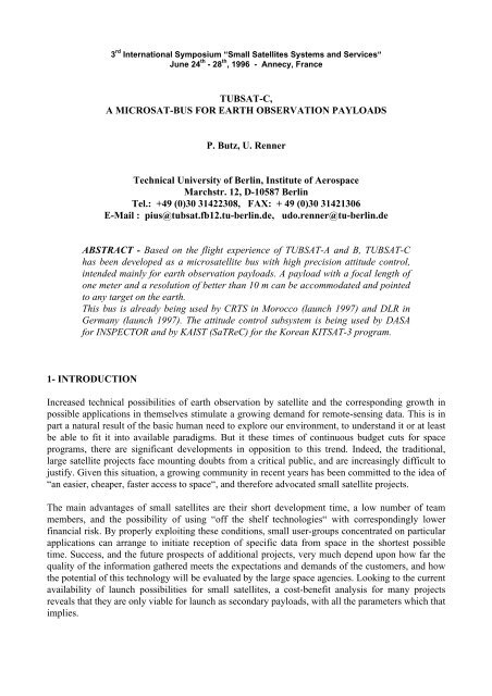
3 rd International Symposium “Small Satellites Systems and Services“<br />
June 24 th - 28 th , 1996 - Annecy, France<br />
TUBSAT-C,<br />
A MICROSAT-BUS FOR EARTH OBSERVATION PAYLOADS<br />
P. Butz, U. Renner<br />
Technical University of Berlin, Institute of <strong>Aerospace</strong><br />
Marchstr. 12, D-10587 Berlin<br />
Tel.: +49 (0)30 31422308, FAX: + 49 (0)30 31421306<br />
E-Mail : pius@<strong>tubsat</strong>.fb12.tu-berlin.de, udo.renner@tu-berlin.de<br />
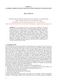
ABSTRACT - Based on the flight experience of TUBSAT-A and B, TUBSAT-C<br />
has been developed as a <strong>microsat</strong>ellite <strong>bus</strong> with high precision attitude control,<br />
intended mainly <strong>for</strong> <strong>earth</strong> <strong>observation</strong> payloads. A payload with a focal length of<br />
one meter and a resolution of better than 10 m can be accommodated and pointed<br />
to any target on the <strong>earth</strong>.<br />
This <strong>bus</strong> is already being used by CRTS in Morocco (launch 1997) and DLR in<br />
Germany (launch 1997). The attitude control subsystem is being used by DASA<br />
<strong>for</strong> INSPECTOR and by KAIST (SaTReC) <strong>for</strong> the Korean KITSAT-3 program.<br />
1- INTRODUCTION<br />
Increased technical possibilities of <strong>earth</strong> <strong>observation</strong> by satellite and the corresponding growth in<br />
possible applications in themselves stimulate a growing demand <strong>for</strong> remote-sensing data. This is in<br />
part a natural result of the basic human need to explore our environment, to understand it or at least<br />
be able to fit it into available paradigms. But it these times of continuous budget cuts <strong>for</strong> space<br />
programs, there are significant developments in opposition to this trend. Indeed, the traditional,<br />
large satellite projects face mounting doubts from a critical public, and are increasingly difficult to<br />
justify. Given this situation, a growing community in recent years has been committed to the idea of<br />
“an easier, cheaper, faster access to space“, and there<strong>for</strong>e advocated small satellite projects.<br />
The main advantages of small satellites are their short development time, a low number of team<br />
members, and the possibility of using “off the shelf technologies“ with correspondingly lower<br />
financial risk. By properly exploiting these conditions, small user-groups concentrated on particular<br />
applications can arrange to initiate reception of specific data from space in the shortest possible<br />
time. Success, and the future prospects of additional projects, very much depend upon how far the<br />
quality of the in<strong>for</strong>mation gathered meets the expectations and demands of the customers, and how<br />
the potential of this technology will be evaluated by the large space agencies. Looking to the current<br />
availability of launch possibilities <strong>for</strong> small satellites, a cost-benefit analysis <strong>for</strong> many projects<br />
reveals that they are only viable <strong>for</strong> launch as secondary payloads, with all the parameters which that<br />
implies.
Over the last few years, the Technical University of Berlin has per<strong>for</strong>med a satellite concept <strong>for</strong><br />
low-cost, high-resolution <strong>earth</strong> <strong>observation</strong> [4]. One important part of this concept is the TUBSAT-<br />
C <strong>bus</strong>, which will be described in further detail below.<br />
2 - THE TUBSAT-C BUS<br />
To accomplish the requirements of the two next missions (DLR-TUBSAT, Morocco-Sat), the<br />
standard <strong>bus</strong> system must be adaptable to different kinds of payloads. This implies a special<br />
flexibility concerning the electrical interfaces and in addition to that a modular mechanical design.<br />
ACS<br />
Star Tracker<br />
x-Gyro y-Gyro z-Gyro<br />
x-Wheel y-Wheel z-Wheel<br />
x-Rate Ctrl y-Rate Ctrl z-Rate Ctrl<br />
Magnetorquer<br />
S-Band Subsys<br />
S-Band<br />
Transmitter<br />
FM Modem<br />
Current<br />
Sensing<br />
Power<br />
Distribution<br />
DC/DC<br />
Converter<br />
PCU<br />
switched Power Bus<br />
MUX<br />
µP<br />
OBDH<br />
Memory<br />
Prom / EEprom / SRAM<br />
serial Lines<br />
Reset<br />
Generator<br />
A/D<br />
Payload Interface<br />
Separation Switch<br />
Arming Plug<br />
unswitched Power Bus<br />
Battery<br />
Charge Reg<br />
TTC1<br />
RTC<br />
TTC2<br />
RTC<br />
NiH 2<br />
Battery<br />
Umbilical Lines<br />
Ground<br />
Interface<br />
Solar Arrays<br />
µP<br />
FFSK Modem<br />
VHF<br />
Transceiver<br />
µP<br />
FFSK Modem<br />
VHF<br />
Transceiver<br />
Fig. 1: Block Diagram of the TUBSAT-C Bus Design<br />
2
2.1 - Structure<br />
3 Reaction Wheels<br />
Star Sensor<br />
3 Gyros<br />
VHF Antenna<br />
NiH 2<br />
Batteries<br />
OBDH<br />
TTC-Units<br />
S-Band Transmitter<br />
S-Band Antenna<br />
Solar Panel<br />
Fig. 2: Mechanical Structure and Assembly of the TUBSAT-C Bus<br />
The TUBSAT-C <strong>bus</strong> (Figure 1,2) consists of two modular compartments. Each is manufactured of<br />
an aluminum block in the <strong>for</strong>m of a box open on one side. All available modules have surface<br />
measurements of 320mm x 270mm. The modular design allows a functional division among the<br />
various subsystems of the satellite, so that each module can be developed, built, and tested<br />
separately. The flexibility thus achieved is highly advantageous <strong>for</strong> adapting the <strong>bus</strong> to various<br />
payloads or missions. The main compartment contains the entire Attitude Control System (ACS),<br />
On-Board Data Handling (OBDH) unit, S-band system, and Power Conditioning Unit (PCU). The<br />
battery compartment contains four NiH 2 cells, Telemetry Tracking and Command (TTC) units,<br />
and various housekeeping units. The net mass of these two modules is 3.2 kilograms. The first<br />
natural frequency of the mounted system is about 250 Hz.<br />
2.2 - Electrical Power Subsystem<br />
The power supply <strong>for</strong> the TUBSAT-C <strong>bus</strong> consists of three component groups:<br />
• Batteries<br />
• Solar panels<br />
• Power conditioning and switching unit<br />
3
The battery block contains four RNCH-12-3 NiH 2 cells, each with a nominal voltage of 2.5V and a<br />
capacity of 12 Ah. These cells were developed by Eagle-Picher specifically <strong>for</strong> aerospace<br />
applications. NiH 2 technology has the advantage of allowing a high number of possible chargedischarge<br />
cycles. This substantially lengthens battery life, especially in low <strong>earth</strong> orbit (LEO).<br />
Only negligible degradation has been observed in a variety of tests, even after 10,000 cycles (about<br />
2 years in orbit) at a discharge depth of 40%. [1] An additional advantage of NiH 2 technology is<br />
that it is not particularly liable to overcharging. For this reason, the most recent <strong>bus</strong> concept<br />
<strong>for</strong>esees no need <strong>for</strong> redundancy in the battery charge regulation, and instead connects one solar<br />
panel directly to the batteries (Autonomous Trickle Charging).<br />
The solar panels were assembled by DASA on a carbon fiber composite base. Each consists of one<br />
row of 34 high-efficiency Sharp BSR silicon cells (17%). Each panel supplies a maximum output<br />
power of about 12 W.<br />
The charge regulator constantly monitors all current battery charge levels and provides protection<br />
against overcharge or deep discharge, especially in cases where low battery level is detected and<br />
all nonessential loads must be switched off.<br />
The DC-DC converter and the power distribution device are located inside the Power Conditioning<br />
Unit (PCU). It can switch 8 different loads simultaneously, while constantly monitoring current<br />
levels and providing protection against short-circuit.<br />
Payload Compartments<br />
Solar Panel<br />
Forefield Sensor<br />
Main Sensor<br />
(Focal Length 1m)<br />
Separation<br />
Mechanism<br />
Fig. 3: The TUBSAT-C Bus used in the DLR-TUBSAT Project<br />
4
2.3 - Thermal Control<br />
Passive thermal control is more than adequate <strong>for</strong> the TUBSAT-C <strong>bus</strong>, since most of the time the<br />
satellite is on standby attitude control, in a kind of barbecue mode. During the relatively brief<br />
operating times when the payload is reoriented to the <strong>earth</strong>, sufficient thermal control is achieved<br />
just by the satellite’s excellent internal heat conduction.<br />
2.4 - Telemetry Tracking and Command Subsystem (TTC)<br />
The two redundant TTC Units, located inside the battery compartment, are connected to the<br />
OBDH via interrupt-controlled serial links. Both units are always in active mode, powered via a<br />
constant, unswitched power line with short-circuit protection.<br />
Upon receipt of the standard telemetry request command from the ground station, 32 different<br />
telemetry channels are sampled, including temperature, voltage, current, etc. The results are<br />
transmitted back directly as a standard telemetry report. This telemetry sample routine is also<br />
carried out automatically at regular intervals, and stores the housekeeping data in a ring buffer<br />
inside the OBDH system as whole orbit data. In addition, on-board memory can be employed as<br />
part of store-and-<strong>for</strong>ward communication. This is especially useful when replacing or<br />
supplementing TUBSAT-A in running projects (deer tracking, polar research, etc.) Access to TTC<br />
is codeworded and protected by CRC, and includes user priority handling. All successfully<br />
received commands are stored in the on-board command history log.<br />
As a rule, the accuracy of the public domain NORAD data, until now normally used <strong>for</strong> tracking<br />
TUBSAT-A and B, is no longer adequate <strong>for</strong> missions requiring high image-resolution. The TTC<br />
there<strong>for</strong>e employs a simple but efficient method to complement NORAD data. Sunrise and sunset<br />
times are recorded with high accuracy using the status of the solar cells. The in<strong>for</strong>mation is<br />
incorporated in the on-board orbit model through numerical filters. This allows the calculation of<br />
the true anomaly with accuracy’s of up to 0.06° (TUBSAT-A, B).<br />
Frequency<br />
VHF<br />
Antenna<br />
Monopole<br />
Output Power 2-5W<br />
Modulation FFSK FM<br />
Baudrate RF 1200-4800 Baud<br />
Mass<br />
0.8 kg<br />
Dimension<br />
204 x 75 x 26 mm<br />
Interface<br />
serial TTL / RS422<br />
Table 1: Summary of the TTC Unit<br />
2.5 - S-Band Subsystem<br />
Image in<strong>for</strong>mation is conveyed from the payload camera to the ground station via the S-band<br />
subsystem. The S-band transmitter is designed such as to allow both digital and analogue<br />
transmission. In case of an interactive steering of the satellite by the ground station, the spacecraft<br />
controller uses in<strong>for</strong>mation presented via graphic interface to control satellite position and rotation<br />
using a trackball-joystick combination. An on-board image compression algorithm reduces<br />
5
equired graphic in<strong>for</strong>mation to achieve an image repetition frequency of about 1 Hz. All other<br />
data (telemetry, star sensor data, etc.) can also be sent over S-band, controlled by the OBDH.<br />
A modified transmitter with BPSK modulation and a baud rate of 256 kBaud has been chosen <strong>for</strong><br />
use in the satellite built in cooperation with CRTS Morocco.<br />
Frequency 2200 MHz<br />
Antenna Hemi (4dB)<br />
Output Power 2-5W<br />
Modulation FM<br />
Baudrate 128 kBaud<br />
Mass<br />
0.6 kg<br />
Dimension 100 x 70 x 40 mm<br />
Table 2 Summary of the S-Band System<br />
Main Sensor<br />
VHF/UHF<br />
Antennas<br />
Star Sensor<br />
Payload<br />
DHS<br />
S-Band Antenna<br />
Separation<br />
Mechanism<br />
Fig. 4: The TUBSAT-C Bus used in the Morocco-Sat Project<br />
6
2.6 - On-Board Data Handling System (OBDH)<br />
The OBDH system is the brain of the satellite. The OBDH monitors and controls all important<br />
procedures and components, including the Attitude Control Unit, Power Conditioning Unit, S-<br />
Band subsystem and payload. Ground station commands received by the TTC units are decoded<br />
and executed within the OBDH Command Interpreter. The electronic design is based upon the 16-<br />
bit, 16 Mhz, single-chip microcontroller from Hitachi, already used in TUBSAT-A and B. Despite<br />
the broad variety of tasks, the amount of memory employed was kept relatively low through<br />
effective programming:<br />
Memory Size (kB) Function<br />
PROM 64 operation system, default cmd. interpreter, basic attitude ctrl. loops<br />
EEPROM 128 enhanced and rebootable functions (code)<br />
SRAM 128 telemetry, log, attitude ctrl. schedule, store and <strong>for</strong>ward etc.<br />
Table 3 Memory Map of the OBDH System<br />
All of the memory employed is radiation hardened and protected against SEU’s (single-event<br />
upsets).<br />
Most of the subsystems are connected via an interrupt-controlled serial link in RS422 or TTL<br />
standard.<br />
2.7 - Attitude Determination and Control System<br />
The ACS consists of four different components:<br />
• Star sensor<br />
• 3 Reaction wheels<br />
• 3 Optical gyros<br />
• Magnetorquer<br />
The star sensor model, KM 1301, is an electro-optical device designed to collect and process star<br />
tracking and attitude determination data. It was developed by the Technical University of Berlin<br />
using the flight experience of TUBSAT-A and B, and manufactured by Kayser-Threde.<br />
The core element of the star sensor is a radiation tolerant 288 x 384 CCD matrix (Thomson),<br />
which translates star images detected through the lens into electronic in<strong>for</strong>mation. After correcting<br />
temperature-dependent dark current, the analogue signal is converted into digital data and acquired<br />
by a microcontroller. The same microcontroller handles sensor timing, <strong>for</strong> example exposure and<br />
conversion times and interfaces with the star-recognition electronics. A second microcontroller,<br />
built into the star- recognition electronics, handles a carefully selected star catalogue and a special<br />
pattern-recognition database. In the inertial mode, the star sensor provides 3-axis attitude<br />
in<strong>for</strong>mation in <strong>for</strong>m of Euler-Angles, Quaternions or Trans<strong>for</strong>mation Matrix. This in<strong>for</strong>mations<br />
can also be calculated as an 3-axis attitude difference between a reference and an actual star<br />
pattern. The default update period is 250ms and the first inertial acquisition is per<strong>for</strong>med within<br />
approximately 0.3 seconds. A medium accuracy of ± 0.02° with a focal length of 16 mm is<br />
sufficient <strong>for</strong> the current mission requirements.<br />
7
dimensions 112 x 95 x 45 mm<br />
mass<br />
0.55 kg<br />
power consumption 4.2 W<br />
input voltage 12 to 15 VDC<br />
pixel size 23 x 23 µm<br />
number of pixel 288 x 384<br />
focal length 16 mm<br />
field of view 21° x 31° (f=16 mm)<br />
update period 250 ms<br />
star acquisition time 0.3 s (first acquisition)<br />
accuracy<br />
± 0.02° (f=16 mm)<br />
interface<br />
serial RS422/485<br />
Table 4: Summary of the Star Sensor KM 1301<br />
The three fibre-optical gyros are used to control the rotation rate around each of the satellite’s axis.<br />
The loop itself (PI-Type) is closed inside every gyro-wheel couple separately and receives its<br />
target value from the OBDH System. There is the possibility to choose between two types of<br />
gyros, depending on the occasional mission requirements. The technical data are listed below<br />
(Table 5,6).<br />
bias drift<br />
< 6°/h<br />
noise < 1°/ h<br />
measuring range ± 1000 °/s<br />
scale factor error < 0.3 %<br />
dimensions<br />
100 x 65 x 20mm<br />
mass<br />
0.15 kg<br />
power consumption < 2 W at 5 VDC<br />
interface<br />
RS422<br />
Table 5: Summary LITEF Gyro<br />
bias drift<br />
< 1.5°/h<br />
noise < 0.3°/ h<br />
measuring range ± 200 °/s<br />
scale factor error < 0.08 %<br />
dimensions<br />
110 x 85 x 70mm<br />
mass<br />
0.68 kg<br />
power consumption 3 W at 5, ±15 VDC<br />
interface<br />
TTL / RS422<br />
Table 6: Summary TELDIX Gyro<br />
The design of the reaction wheels, developed by the Technical University of Berlin and<br />
manufactured by IRE, is especially suited to the requirements of mircosatellites.<br />
Three different operation modes are available:<br />
• Speed control mode (a user commanded speed is kept with an accuracy of ± 1°/s).<br />
• Current control mode (the wheel is running with a user commanded current).<br />
• Torque control mode (a user commanded net torque is kept with an accuracy of ±0.02<br />
mNm).<br />
The magnetorquer is used to desaturate the reaction wheels and to keep a reasonable angular<br />
momentum, in particular to ensure a slow rotation (barbecue mode) in the times when the ACS is<br />
switched off.<br />
8
max. angular momentum 0.25 Nms at 12 VDC<br />
max. speed<br />
5700 rpm at 12 VDC<br />
max. torque<br />
28 mNm<br />
speed accuracy ± 1°/s<br />
dimensions<br />
80 x 80 x 70 mm<br />
mass<br />
0.9 kg<br />
power consumption 1 W (steady state)<br />
interface<br />
TTL / RS422<br />
Table 7: Summary Reaction Wheels (IRE)<br />
3 - TYPICAL (PRE)-MISSION PROCEDURE<br />
A very important aspect of the mission scenario is a kind of hibernation mode in which the<br />
spacecraft spends most of the time. In that mode, there is no need <strong>for</strong> observing or controlling vital<br />
functions via the ground station.<br />
The following general start-up and acquisition sequence describes the steps involved in switching<br />
the satellite from hibernation mode (ACS off) into an operations mode <strong>for</strong> recording specific areas<br />
of the <strong>earth</strong>’s surface by the payload camera:<br />
1. At a preprogrammed time, typically a few minutes be<strong>for</strong>e the crossing, the OBDH system<br />
switches all attitude control systems on, and starts reducing satellite rotation by means of a rate<br />
damping process. With the 3 gyros as body fixed rotation sensors, the closed loop is conveying the<br />
current angular momentum of the spacecraft onto the three reaction wheels. The residual motion<br />
amounts to less than 0.01°/sec.<br />
2. If the star sensor is now blinded by the <strong>earth</strong> or the sun, a slew maneuver will be per<strong>for</strong>med to<br />
align the sensor to stars by using in<strong>for</strong>mations gathered from both the internal orbit model and the<br />
solar cells. The star sensor now determines the current position of the satellite in the inertial<br />
system, making this in<strong>for</strong>mation available to the OBDH in <strong>for</strong>m of Euler Angles or Quaternions.<br />
3. The OBDH proceeds to carry out a comparison of current position with the preprogrammed<br />
intended values, in order to determine optimal parameters <strong>for</strong> the minimum three different slew<br />
maneuvers (controlled by the gyros). In order to minimize inaccuracies arising through axis<br />
coupling, the system uses every opportunity to update inertial system positioning through repeated<br />
star sensor recordings.<br />
4. After carrying out the slew maneuvers, the predefined position is reached by closing the attitude<br />
control loop with the star sensor along all three axes. Pointing accuracy in this mode is better than<br />
± 0.03° and limited by the star sensors per<strong>for</strong>mance (mainly the focal length).<br />
5. The position thus achieved serves as an optimal starting point <strong>for</strong> the subsequent <strong>observation</strong><br />
mission, whether or not automatic target pursuit is now employed, or an interactively determined<br />
profile is instead commanded from the ground station.<br />
9
One means of determining potential pointing accuracy is to direct the payload camera (focal length<br />
1m) at a star. By using an observer model including the current angular momentum and<br />
disturbance torque, a pointing accuracy of a few arcsec can be achieved on two axes.<br />
REFERENCES:<br />
[1] D. Coates, W. Cook, S. Wecker, C. Fox : “Small Diameter CPV Nickel-Hydrogen<br />
Batteries <strong>for</strong> Small Satellite Applications“, International Symposium on Small<br />
Satellites Systems and Services, Biarritz, France, July 1994<br />
[2] Sven Grahn, Anna Rathsman: “An Attempt to make Microsatellite a useful tool <strong>for</strong><br />
Space Science“, 9th Annual AIAA/USU Conference on Small Satellites, Logan, Utah,<br />
September 1995<br />
[3] Sungheon Kim, Sungdong Park, Dan Keun Sung, Soon Dal Choi: “Mission<br />
Overview of Engineering Test Satellite, KITSAT-3“, 9th Annual AIAA/USU<br />
Conference on Small Satellites, Logan, Utah, September 1995<br />
[4] U. Renner, B. Lübke-Ossenbeck, P. Butz: “TUBSAT-A,B,C“, International<br />
Symposium on Small Satellites Systems and Services, Biarritz, France, July 1994<br />
10