Three - University of Arkansas Physics Department
Three - University of Arkansas Physics Department
Three - University of Arkansas Physics Department

You also want an ePaper? Increase the reach of your titles
YUMPU automatically turns print PDFs into web optimized ePapers that Google loves.
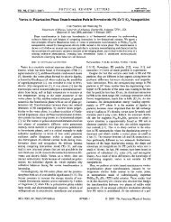
CLE0'97. Conference on Lasers and Electro-Optics, v 11, p 216,1997<br />
--<br />
Requestors must comply with<br />
Copyright law (Title 17 U.S. Code)<br />
216 / CLE0'97 / WEDNESDAY MORNING<br />
CWES<br />
9:U am<br />
Self-trapplng <strong>of</strong> twedlmenslonal optloal<br />
beams and Ilght-Induced waveguldlng In<br />
photorefractlve InP at<br />
telecommunlcatlon wavelengths<br />
M. Chauver, S. A. Hawkins, G. J. Salamo,<br />
M. Segev,' D. F. Bliss,** G. Bryant,"<br />
Depurtmenr <strong>of</strong> <strong>Physics</strong>, <strong>University</strong> <strong>of</strong>Arkan~s.<br />
Fayetteville. <strong>Arkansas</strong> 72701<br />
Optical spatial soliton^^-'^ in photorefractive<br />
crystals <strong>of</strong>fer potential applications in the field<br />
<strong>of</strong> all-optical switching and beam steering. A<br />
photorefractive solit011 is crcated when a photoinduced<br />
index change exactly compensates<br />
for thedifhction <strong>of</strong> the beam. In thissensethe<br />
beam is able to createits own waveguide. These<br />
effects have been extel~sively studied in Ferroelectric<br />
oxide and sillenite oxide crystals for<br />
visible wavelengths. For the near infrared<br />
wavelengths used in telecomm~mications. In-<br />
P:Fe crystals have already demonstrated intereslilig<br />
pliolorefractive proper tie^.".'^ Sdftrappin<br />
<strong>of</strong> a laser beam has been reported in<br />
1nP:Fe.' In this paper we report the first observation<br />
<strong>of</strong> the use <strong>of</strong> a two-dimensional soliton<br />
formed at 1.3 pm in InP to produce a<br />
waveguide to guide a second lasu beam at 1.55<br />
Pm.<br />
For the experiment, the beam from a<br />
Nd:Yas laser at 1.3 pm is collimated and focused<br />
with a 5-cn~ focal length lais on the<br />
entrance face <strong>of</strong> an 1nP:Fe crystal whose temperature<br />
is stabilized at 297 K. As shown in Fib<br />
1, the electric tield, P., is applird along (I lo),<br />
the beam propagates along (I iO), and is polarized<br />
either horizontally or vertically at 45'<br />
From (110).<br />
The beam size at the entrance face <strong>of</strong> the<br />
crystal has a diameter <strong>of</strong> ahnut 55 pm and<br />
diverges to a 170 pm diameter a1 the exit face<br />
when no field is applied to the crystal. The<br />
1nP:Fe crystal length is 1 cm in the direction <strong>of</strong><br />
the propagation. Mien a 12 kV/cm field is<br />
applied to the crystal, the beam is trapped and<br />
the beam diameter at the exit face is reduced to<br />
about 55 ~m. Our experiments show that the<br />
beam is trapped to the same diameter for either<br />
a 1 cm or a 0.5 cm crystal length, supporting<br />
rhe condusion that the trapped diameter is the<br />
same throughout the crystal. To show that an<br />
efficient waveguide is formed in the crystal, we<br />
have also propagated a 1.55 pn (~0.1<br />
~~.Wlcm~) laser beam collinear to the 1.3 pm<br />
(I Wlcm2) trapped laser beam. To observe<br />
only the 1.55 pm beam, a color filter is placed<br />
after the crystal. When both beams are verti-<br />
CWE5 Fig. 1 ApyaraLus iud cryslal oricn~ation<br />
for observing two-dimensional waveguide<br />
formation by the 1.3 pm laser bcam and guiding<br />
<strong>of</strong> the 1.55 krn lascr bcam.<br />
CWE5 Fig. 2 Image <strong>of</strong> a 1.55 prn wavelength<br />
beam at the exit face <strong>of</strong> the crystal without (left)<br />
and with (right) the 1.3 pm trapped bean1<br />
prewr. Top: both beams vertically polarized;<br />
bottom: 1.3 pm beam horizontally polarized and<br />
1.55 pm beam vertically polorizcd. % = 12<br />
kVlcm.<br />
cally polarized, the 1.55 p.m beam is observed<br />
to be guided along the same direction as the 1.3<br />
pm beam (Fig. 2a). However, when the pokrization<br />
<strong>of</strong> the 1.3 pm beam is horizontal and<br />
the 1.55 pm beamverlid, the 1.55 pm beam<br />
is guided on the tide <strong>of</strong> the 1.3 pn trapped<br />
beam (Fig. 2b). While in both cases the 1.55<br />
pm beam is effectively guided, we can see that<br />
when the 1.3 p.m beam is horizontally polar-<br />
bed, tlie 1.55 w~i bed111 is efficier~tly guided<br />
and has a near circular pr<strong>of</strong>ile.<br />
To measure the index change responsible<br />
for the formation <strong>of</strong> the waveguide we added<br />
an interferometer to the apparatus. This measurement<br />
gives an increase <strong>of</strong> the refranive<br />
index in the center <strong>of</strong> the horizontally polarized<br />
1.3 p11ibeamandaslrongdarm (lo-')<br />
<strong>of</strong> the index on one side <strong>of</strong> beam. 'lhis amazinglystrongdecrcase<strong>of</strong><br />
the indeximplies that a<br />
large photorefractive space charge field is<br />
present. We calculate this space chqe field to<br />
be about 50 KV/cm when the applied external<br />
field across the crystal is only 5 KVIcm. When<br />
the polarization <strong>of</strong>the 1.55 w beam is made<br />
vertical the large index change on the side <strong>of</strong><br />
the focused 1.3 lr~n beam is seen as an increase<br />
in index and the 1.55 pm beam is guided.<br />
Despite the small value <strong>of</strong> the electro-optic<br />
codficient it is clearly possible to induce<br />
large index changes. Physically, the large index<br />
change is due to the large space charge field<br />
that call be created as a result <strong>of</strong> the intensity<br />
temperature resonance and the low value <strong>of</strong><br />
the dielectric constant associated with InP.<br />
*Depamnent <strong>of</strong> Electrical Engineering and Advnnccd<br />
Crntrrfir Photmics and Optoelectronic<br />
Mnrerials, Princeton <strong>University</strong>, Princeton, New<br />
Jersey 08544<br />
**U.S. Air Force, Rome Laboratory. Hanscom<br />
Air Force Bare, Marsachusetts 01731<br />
1. M. Segev, B. Crosignani, A. Yariv, D. Fischer.<br />
Phys. Rev. Lett. 68.923 (1992).<br />
2. G. Duree, 1. L. Shulk, G. Salamo, M. Segev,<br />
A, Yariv, B. Croaignani, P. DiPorto,<br />
E. Sharp, R2 Neurgaodar, ~hys. RW.<br />
Lctt. 71,533 (19.93).<br />
3. G. C. Valley, M. Segev, B. Crosignanj, A.<br />
Yariv, M. M. Fejcr, M. Bashaw, Phys.<br />
Rev. A 50, Rapid Comm., R4457 (1994).<br />
4. M. Taya, M. Bashaw, M. M. Fejer, M.<br />
Segev,G. C. Valley, Phys. Rev. A 52,3095<br />
(1995).<br />
5. M. Segev, G. C. Valley, R. Crosignani, P.<br />
DiPorto, A. Yoriv, Phys. Rev. Lett. 73,<br />
3211 (1994).<br />
6. D. N. Christodoulides, M. I. Carvalho, I.<br />
Opt. Soc. Am. B 12, 1628, (1995).<br />
7. M. Segev, M. Shih, G. C. Valley, J. Opt.<br />
Soc. Am B 13,706 (1996).<br />
8. Study-stale self-focusing effects in a biased<br />
photorefractive crystal were first observed<br />
by M D. Iturbe-Castillo, P. A.<br />
Marqua-Aguh, 1. J. Sanchez-Mondragon,<br />
S. Stepanov, V. Vysloukh. Appl. Phys.<br />
Lett. 64,408 (1994).<br />
9. M. Shih, M. Segev, G. C, Valley, G.<br />
Salamo, B. Crosignani, P. DiPurto, Electron.<br />
Lett. 31, 826 (1995); M. Shih, P.<br />
Leach, M. Segev, M. Garrett. G. Salamo,<br />
G. C. Valley, Opt. Lett. 21,324 (1996).<br />
10. Mitchell, 2. Chen, M. Shih, M. Segev,<br />
Phys. Rev. Lett. 77,490 (1996).<br />
11. V. Vieux,P. Gravey,N. Wolfer, G. Picoli,<br />
Appl.Phys. Lett. 58,2880 (1991).<br />
12. ti. Picoli, P. Gravey, C. Ozkul, V. Vieux,<br />
J.Appl. Phys. 66,3798 (1989).<br />
13. M. Chauvet, S. A. Hawkins, G. I. Salamo,<br />
M. Segn: D. F. Bliss, G. Blyant, Opt.<br />
Lett. 21, 1333 (1996).<br />
Gagphase reducedbackIpound<br />
abeorptlon spectroscopy<br />
John N. Sweetser, Rick'l'rebino, Combustion<br />
Research Fuciliry. MS9057, Sandin National<br />
Laboratories, Livermore, California 94551 -<br />
0969; E-mail. jnsweet@sandia.gov<br />
An important ~oal in optical diagnostics for<br />
trace species detection in combustion is to be<br />
able to perform sensitive absorption spectroscopy.<br />
Current methods that achieve this goal,<br />
such as frequency-modulation, Fourier-transform,<br />
cavity-ring-down, multi-photon, and<br />
photoacoustic spectroscopies all require scanning<br />
in frequency or time, which is slow compared<br />
with the relevant time scale for variation<br />
in tl~e medium under study. A sensitive singleshot<br />
(i.e., rapid) method is therefore highly<br />
desirable.<br />
It is straightfonvard to obtain a single-shnt<br />
absorption spectrum simply by sendinga burst<br />
<strong>of</strong> broadband light or an ultlashort laser pulse<br />
through the absorbing medium and then Leasuring<br />
the spectrum <strong>of</strong> the transmitted pulse<br />
with a spectrometer. Unfortunately, such a<br />
simple method has severely limited sensitivity.<br />
Small changes in the light spectrum resulting<br />
from ahsorption are dwarfed by the spectnmm<br />
<strong>of</strong> the input light and pixel-to-pixel variation<br />
ir~ resyonsivily <strong>of</strong> the dctectur. If one could<br />
reduce this background, without significantly<br />
reduangthe absorption dips, then the goal <strong>of</strong> a<br />
sensitive single-shot absorption-spectroscopy<br />
method would be achievcd.<br />
Techniquesthat attempt to accomplish this<br />
eoal with use <strong>of</strong> interferometers fail because<br />
interferometers are too sensitive to alignment,