Three - University of Arkansas Physics Department
Three - University of Arkansas Physics Department
Three - University of Arkansas Physics Department

You also want an ePaper? Increase the reach of your titles
YUMPU automatically turns print PDFs into web optimized ePapers that Google loves.
476 / CLE0'99 / THURSDAY AFTERNOON<br />
CLEO '99. Conference on Lasers and Electro-Optics, p 476-791999<br />
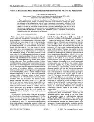
mhS6 Fig. 1. Maximum instability for different<br />
grating strength ratios, y and negative$<br />
Plotted here is growth rate versus phase mismat&,<br />
p, and intensity. Dimensionlcrs parameters<br />
usedare ru = 1, f = - 1, (a) y = 10; (b) y 4.<br />
Note that all axes are scaled differently.<br />
where r, = $)/vy) is the ratio <strong>of</strong> group velocity<br />
<strong>of</strong> the fundaments! (FH) and the second<br />
harmonic (SH), p = r,&k,/~, is a normalized<br />
phasemismatch and y = ~ .K~/K, is theratio<strong>of</strong><br />
the grating strengths to SH and FH.<br />
The continuous wave (CW) solutions can<br />
be written as:<br />
where aj, are amplitudes, is the frequency<br />
and Q is the wavenumber <strong>of</strong> the CW solution.<br />
a<br />
af<br />
a,- = -<br />
Qlf = -$q'<br />
fi'<br />
a,, = -fZ Q - $1,a2-= -f-'- Q-$1,<br />
(3)<br />
where f is a parameter that indicates the position<br />
<strong>of</strong> the solution w.r.t. the FH band-gap.<br />
Choosing f and as free parameters, we find<br />
that Q is given by: AQ~<br />
A = 2r,V2 - 1)<br />
+ BQ + C = 0 where<br />
B = (1 f2)(y - p - 2a) - 2r.<br />
x (1 -'y-~p<br />
-.f3n)/f<br />
C = (- 1 k fl)(p(l 2 f' t f a) + R(2<br />
5 2f2 t zn)))/f. (4)<br />
Once Q has been determined, we obtain an<br />
equation for a, which reads, a' = (2n f p 2<br />
y)(ff-'t 2n)'2rUQ(-f-Cf-Ik2Q).<br />
Following standard procedure, we add<br />
small perturbations to the CW solutions and<br />
study their wolution. This leads to an 8 X 8<br />
matrix, the largest imaginary part <strong>of</strong> the eigenvalues<br />
<strong>of</strong> this matrix correspond to the instability<br />
growth rate <strong>of</strong> the CW solution. The<br />
main difficulty is that there are five degrees <strong>of</strong><br />
freedom in choosing the parameters: r,,J y, p<br />
and $1.<br />
We can narrow our search range by dixussing<br />
the physical significance <strong>of</strong> the five parameters:<br />
(1) r,, the ratio <strong>of</strong> material goup velocities<br />
at the FH and the SH. For most nonlinear<br />
optical materials, this ratio is usually around<br />
unity. <strong>Three</strong> values, r, = 0.5; 1.0, 2.0 were<br />
chosen to represent a large range <strong>of</strong> pouible<br />
situations. (2) f gives the position <strong>of</strong> a CW<br />
solution with respect to the fundamental<br />
band-gap. Typical values <strong>of</strong>f are f = 20.1,<br />
t0.5, 1.0. Note that f and l/fare equivalent.<br />
the only difference being the direction <strong>of</strong><br />
propagation.' (3) y represents the relative<br />
strength <strong>of</strong> the gratings at the FH and the SH.<br />
The following values y = 0.1,0.5,1,2,10 cover<br />
a large range <strong>of</strong> possible physical configurations<br />
( ty lead to the same results). We treat<br />
the two remaining parameters, p and R, as<br />
"free," and scan p, and space for MI at a<br />
given set <strong>of</strong> the other parameters.<br />
In general, most CW solutions are unstable.<br />
Stable areas are found in the nonlinear Schrddiiger<br />
limit, and if the grating strength <strong>of</strong> the<br />
SH is significantly larger than that <strong>of</strong> the FH.<br />
Here we present examples <strong>of</strong> the latter with, y<br />
= 10.4, and f = - 1. The fundamental excitation<br />
is now just above the band-gap, giving<br />
anomalous dispersion. However, the sign <strong>of</strong><br />
the coupling constant indicates that the nonlinear<br />
coupling is predominantly to secondharmonic<br />
modes below the bandgap, which<br />
have normal dispersion. Therefore, the quasimodes<br />
that are coupled have opposite signs <strong>of</strong><br />
dispersion, a necessary condition for stabity<br />
in the EMA limit. Note from Figs. 1 that the<br />
sign <strong>of</strong> the phase mismatch is also important.<br />
*<strong>Department</strong> <strong>of</strong> <strong>Physics</strong>, <strong>University</strong> <strong>of</strong> Queencland,<br />
QLD 4072, Australia<br />
**<strong>Department</strong> <strong>of</strong> Interdisciplinary Studies, Faculty<br />
<strong>of</strong> Engineering, Tel Aviv <strong>University</strong>, Tel<br />
Aviv 69978, Israel<br />
I. B. J. Eggleton, C. M. de Sterke, R. Slusher,<br />
and J. Sipe, Electron. Lett. 32,2341 (1996).<br />
2. H. He and P. D. Drummond, Phys. Rev.<br />
Lett. 78, 4311 (1997); T. Peschel, U. Peschel,<br />
F. Lederer, and B. A. Malomed,<br />
Phys. Rev. E 55,4730 (1997); C. Conti, S.<br />
Trillo, and G. Assanto. Phys. Rev. Lett. 12,<br />
2341 (1997).<br />
3. C. M. de Sterke, J. Opt. Soc. Am. B (1998),<br />
in press.<br />
4. H. He, P. D. Drummond, and B. A.<br />
Malorned, Opt. Commun. 123, 395<br />
(1996); S. Trillo and P. Ferro, Opt. Len. 20,<br />
438 (1995); A. V. Buryakand Y. S. Kivshar,<br />
Phys. Rev. A 51, R41 (1995).<br />
. . CCD Camera<br />
Optical circuitry In photorefractive<br />
strontium barlum nlobate<br />
Matthew Klotz, Mike Crosser.<br />
Gregory J. Salarno. Mordechai Segev,' <strong>Physics</strong><br />
<strong>Department</strong>, <strong>University</strong> <strong>of</strong><strong>Arkansas</strong>,<br />
Fayetteville, Arizona 72701 USA; E-mail:<br />
mklotz@comp.uark.edu<br />
Optical spatial solitons' in photorefractive<br />
crystals2 have shown potential to form optical<br />
circuitry by forming graded index waveguides<br />
which can guide other beams.'+ A soliton<br />
forms when a photoinduced index change in<br />
the material exactly compensates for the diffraction<br />
<strong>of</strong> the beam; i.e. the beam creates its<br />
own waveguide. In photoreffactivematerials, a<br />
screening soliton is formed by applying an external<br />
electric field that within the incident<br />
light beam is screened by photoinduced<br />
charges.5 The external field then lowers the<br />
refractive index around the screened area, via<br />
the Pockels effect, creating a waveguide. However,<br />
these induced waveguides disappear if the<br />
applied field is removed from the material. In<br />
this paper we report on the use <strong>of</strong> soliton formation<br />
to create permanent waveguides by selectively<br />
reorienting ferroelectric domains<br />
within the incident light beam.<br />
For the experiment, the output <strong>of</strong> an argonion<br />
laser is collimated and focused to a spot<br />
size <strong>of</strong> 12 pm on the front face <strong>of</strong> a 1 cm cubic<br />
SBN:75 crystal. When a 3 kV/cm electric field<br />
is applied to the crystal along the direction <strong>of</strong><br />
the spontaneous polarization, the beam self<br />
focuses to its input diameter. Theexternal field<br />
is then removed and a uniform background<br />
beam that fills the crystal is switched on. The<br />
space charge field due'to photoinducedscreening<br />
charges is larger than the coercive field <strong>of</strong><br />
the ferroelectric domains and causes the domains<br />
in the area <strong>of</strong> the incident beam to reverse<br />
their orientation. At equilibrium, a new<br />
space charge field, due to the bound charge at<br />
the domain boundaries is locked in place. This<br />
new field increases the index <strong>of</strong> refraction in<br />
only the area <strong>of</strong> the original soliton, so that a<br />
waveguide is formed. The waveguides are observed<br />
to have the same size as the original<br />
soliton, exhibit single mode behavior and last<br />
indefinitely.<br />
In addition to fixing a single soliton, a co-<br />
, Delay Arm<br />
CrhS7 Fig. 1. Experimental apparatus for fixing <strong>of</strong> optical circuitry.