Three - University of Arkansas Physics Department
Three - University of Arkansas Physics Department
Three - University of Arkansas Physics Department

Create successful ePaper yourself
Turn your PDF publications into a flip-book with our unique Google optimized e-Paper software.
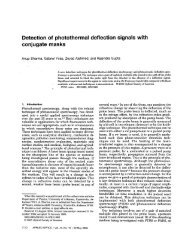
<strong>Three</strong>-dimensional image reconstruction using strontium barium niobate<br />
Brian P. etche el^) and Gary L. Wood<br />
U.S. Army Research Laboratoy, A m : AMSRL-SE-EO, Adelphi, Mayland 20783-1197<br />
Richard J. Anderson<br />
National Science Foundation, Arlington. Virginia 22230<br />
Gregory J. Salamo<br />
Departmenr <strong>of</strong> <strong>Physics</strong>, <strong>University</strong> <strong>of</strong> <strong>Arkansas</strong>, Fayetteville, Arkansm 72701<br />
(Received 27 December 1996; accepted for publication 29 April 1997)<br />
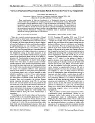
A definitive demonstration <strong>of</strong> the use <strong>of</strong> a photorefractive crystal to project a three-dimensional<br />
image in space is reported on. The image is bright and different perspective views <strong>of</strong> the object<br />
appear as the viewing direction is changed. O 1997 American Institute <strong>of</strong> <strong>Physics</strong>.<br />
[SOOO3-695 1 (97)00427-01<br />
Although four-wave mixing in photorefractive crystals<br />
has been used extensively to store and project twodimensional<br />
holographic images, we report a definitive demonstration<br />
<strong>of</strong> true three dimensional (3D) image reconstruction<br />
using a photorefractive crystal. The use <strong>of</strong> an inorganic<br />
photorefractive crystal as a storage medium allows:<br />
(1) simultaneous recording and read out <strong>of</strong> three dimensional<br />
(3D) holograms possessing easily observable parallax;<br />
(2) the entire holographic process to occur at low light levels<br />
(e.g., rnilliwatt levels for the object beam);<br />
(3) the entire process to occur without processinglfixing the<br />
material; and<br />
(4) thousands <strong>of</strong> holograms to be stored in a relatively small<br />
crystal volume via wavelength andlor angle multiplexing.<br />
Our 3D imaging technique employs a Ce-doped, strontium<br />
barium niobate crystal [(SBN):60 20X20X 1.3 mm] as<br />
the storage medium. Figure 1 is a schematic diagram <strong>of</strong> the<br />
experimental setup used to record and project 3D images.<br />
The summation <strong>of</strong> light beams scattered <strong>of</strong>f <strong>of</strong> the object,<br />
E,, and the reference beam, E2, write a hologram in the<br />
form <strong>of</strong> transmission gratings in the photorefractive crystal.<br />
The read beam, El, counterpropagating to E2, is produced<br />
by phase conjugation <strong>of</strong> E2 by a 13.5X 12.2X 6 mm, Cedoped,<br />
SBN:60 photorefractive crystal acting as a double<br />
phase conjugate mirror (DPCM). The counterpropagating<br />
beam diffracts to form beam Ed that recreates the recorded<br />
3D image at a distance from the crystal equal to that between<br />
the object and crystal (e.g., -40-80 mm). A plate beam<br />
splitter, placed between the object and crystal, is used to<br />
view the real 3D image, produced by Ed. Viewing is accomplished<br />
by:<br />
(1) using the eye, just as one views a conventional hologram;<br />
(2) projecting the image onto a screen or into a scattering<br />
cell; or<br />
(3) using an imaging lens in conjunction with a chargecoupled<br />
device (CCD) or video camera to magnify and<br />
"~lectronic mail: bketchel@arl.mil<br />
record the 3D image. In the latter case, different perspectives<br />
are observed by placing the camera and imaging<br />
lens on a goniometer that is rotated about a fixed pornt<br />
(e.g., the location <strong>of</strong> the 3D image).<br />
Since the recording medium is a photorefractii'c crystal,<br />
unlike conventional holography where photograpliic filp 1s<br />
employed, the hologram can occur in real time with continib<br />
ous recording and display. The geometry emploved iri the<br />
current experiment is readily recognized as being txpical <strong>of</strong><br />
degenerate four-wave mixing, a technique whic!~; has been<br />
compared in the literature to conventional holography bg<br />
Pepper and ~ariv.' One major difference, hnwever, is the use<br />
,. .<br />
<strong>of</strong> a DPCM to provide the read beam, El. .i r~e !.i;:: r .:I:-<br />
DPCM has three well-documented advantages o:cr othe<br />
methods:<br />
(1) distortion introduced by inhomogeneities in the photorifractive<br />
crystal are<br />
(2) high resolution holograms are possible;4 and<br />
(3) as reported here, the 3D image can be observed over a<br />
large perspective range.<br />
One can readily examine the impact <strong>of</strong> the DI'CM on the<br />
perspective range viewed by replacing it with a pldne m11-ror<br />
(P'M). or a separate counterpropagating beam. Analysis<br />
shows that, when this substitution is made, the ab~lity <strong>of</strong> the .<br />
nonphase conjugate counterpropagating beam tr lul fi l l the<br />
Bragg match conditions over the crystal area is extremely<br />
Ar h88r barn<br />
X148nrn<br />
SBN:C8<br />
To CCD, v~deoemrnere,<br />
or eye<br />
FIG. 1. Schematic diagram <strong>of</strong> experimental apparatus<br />
..'.<br />
.<br />
Appl. Phys. Lett. 71 (1). 7 July 1997 00036951/97/71(1)17131L10.00 Q 1997 American Institute <strong>of</strong> <strong>Physics</strong> 7<br />
Copyright 02001. All Rights Reserved.