Three - University of Arkansas Physics Department
Three - University of Arkansas Physics Department
Three - University of Arkansas Physics Department

You also want an ePaper? Increase the reach of your titles
YUMPU automatically turns print PDFs into web optimized ePapers that Google loves.
APPLIED PHYSICS LETTERS VOLUME 78, NUMBER 8 19 FEBRUARY 2001<br />
Wide-bandwidth high-frequency electro-optic modulator based<br />
on periodically poled LiNb03<br />
Yan-qing LU,~) Min Xiao, and Gregory J. Salamo<br />
Depczvlnzenl <strong>of</strong> <strong>Physics</strong>, Universiy <strong>of</strong>Arkun.su.~, Fu~~etleville, A~.hl~lsur 72701<br />
(Received 18 October 2000; accepted for publication 21 December 2000)<br />
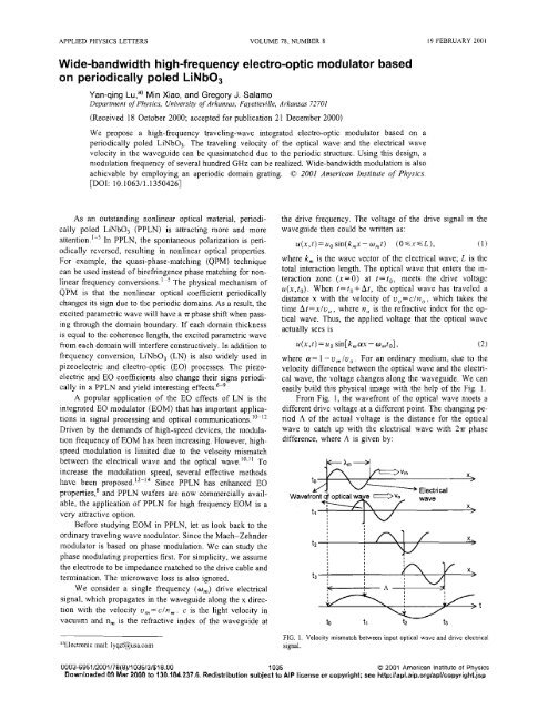
We propose a high-frequency traveling-wave integrated electro-optic lnodulator based on a<br />
periodically poled LiNb03. The traveling velocity <strong>of</strong> the optical wave and the electrical wave<br />
velocity in the waveguide can be qirasin~atched due to the periodic stnlcturc. Using this design, a<br />
n~odulation frequency <strong>of</strong> several hundred GHz can be realized. Wide-bandwidth modulation is also<br />
achievable by employing an aperiodic domain grating. 0 2001 An~erican Institute <strong>of</strong> <strong>Physics</strong>.<br />
[DOI: 10.106311 .I 3504261<br />
As an outstanding nonlinear optical material, periodically<br />
poled LiNb03 (PPLN) is attracting more and more<br />
attention.'-5 In PPLN, the spontaneous polarization is periodically<br />
reversed, resulting in nonlinear optical properties.<br />
For example, the quasi-phase-matching (QPM) technique<br />
can be used instead <strong>of</strong> birefringence phase matching for nonlinear<br />
frequency conversions.' The physical mechanism <strong>of</strong><br />
QPM is that the nonlinear optical coefficient periodically<br />
challges its sign duc to the periodic domains. As a result, the<br />
excited parametric wave will have a nphase shift when passing<br />
through the domain boundary. If each domain thickness<br />
is equal to the coherence length, the excited parametric wave<br />
from each domain will interfere constructively. In addition to<br />
frequency conversion, LiNbO, (LN) is also widely used in<br />
pizeoelectric and electro-optic (BO) processes. Thc piezoelectric<br />
and EO coefficients also change their signs periodically<br />
in a PPLN and yield interesting effects.'-'<br />
A popular application <strong>of</strong> the EO effects <strong>of</strong> LN is the<br />
integrated EO n~odulator (EOM) that has important applications<br />
in signal processing and optical communications.10~'2<br />
Driven by the demands <strong>of</strong> high-speed devices, the modulation<br />
frequency <strong>of</strong> EOM has been increasing. However, highspeed<br />
modulation is limited due to the velocity mismatch<br />
between the electrical wave and the optical wave.10." To<br />
increase the n~odulation speed, several effective methods<br />
have been proposed.'2-'4 Since PPLN has enhanced EO<br />
properties,8 and PPLN wafers are now comrnercially available,<br />
the application <strong>of</strong> PPLN for high frequency EOM is a<br />
very attractive option.<br />
Before studying EOM in PPLN, let us look back to the<br />
ordinary traveling wave n~odulator. Since the Mach-Zehnder<br />
modulator is based on phase modulation. We can study the<br />
phase modulating properties first. For simplicity, we assume<br />
the electrode to be impedance matched to the drive cable and<br />
tellination. The microwave loss is also ignored.<br />
We consider a single frequency (om) drive electrical<br />
signal. which propagates in the waveguide along the x direction<br />
with the velocity u,,=cln,. c is the light velocity in<br />
vacuunl and n, is the refractive index <strong>of</strong> the waveguide at<br />
"Electronic mall: lyqzf@~sa.com<br />
the drive frequency. The voltage <strong>of</strong> the drive signal in the<br />
waveguide then could be written as:<br />
where k, is the wave vector <strong>of</strong> the electrical wave; L is the<br />
total interaction length. The optical wave that enters the interaction<br />
zone (x= 0) at t = to, meets the drive voltage<br />
u(x,to). When t=to-tAt, thc optical wave has traveled a<br />
distance x with the velocity <strong>of</strong> u,=cln,, which takes the<br />
time At=xlu,, where no is the refractive indcx for thc optical<br />
wave. Thus, the applied voltage that the optical wave<br />
actually sees is<br />
where a= 1 - urn lu, . For an ordinary medium, due to the<br />
velocity difference between the optical wavc and tbe electrical<br />
wave, the voltage changes along the waveguide. We can<br />
easily build this physical image with the hclp <strong>of</strong> the Fig. I.<br />
From Fig. 1, the wavefront <strong>of</strong> the optical wave meets a<br />
different drivc voltage at a diffcrent point. Thc changing period<br />
A <strong>of</strong> the actual voltage is the distance for the optical<br />
wave to catch up with thc electl.ica1 wave with 2n phase<br />
difference, where .A is given by:<br />
L.4<br />
Wavefront qf optic<br />
tl<br />
L<br />
i<br />
- Electrical<br />
FIG. 1. Velocity mismatch between input optical wave and drive electrical<br />
signal.<br />
X<br />
0003-6951/2001/78(8)/1035/3/$18.00 1035 O 2001 American Institute <strong>of</strong> <strong>Physics</strong><br />
Downloaded 09 Mar 2008 to 130.184.237.6. Redistribution subject to AIP license or copyright; see http:llaploaip.orglapllcopyright.jap