7. semester Continuum mechanics Solution Exercise 9
7. semester Continuum mechanics Solution Exercise 9
7. semester Continuum mechanics Solution Exercise 9

You also want an ePaper? Increase the reach of your titles
YUMPU automatically turns print PDFs into web optimized ePapers that Google loves.
1<br />
<strong>7.</strong> <strong>semester</strong> <strong>Continuum</strong> <strong>mechanics</strong><br />
<strong>Solution</strong> <strong>Exercise</strong> 9<br />
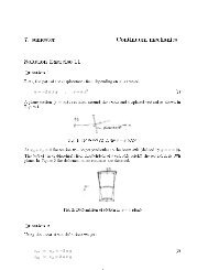
Question 1<br />
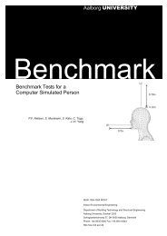
In Figure 1 the deformation for a = 1 and b = 0 is sketched.<br />
Fig. 1: u and v for a = 1 and b = 0<br />
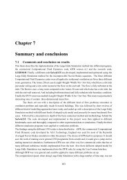
In Figure 2 the deformation for a = 0 and b = 1 is sketched.<br />
Fig. 2: u and v for a = 0 and b = 1<br />
Comments to choice of u:<br />
In Timoshenko's "Theory of Elasticity"the similar problem is treated in Section 21. Ti/-<br />
moshenko nds a dierent solution for u, and indirectly concludes that the shear stiness of<br />
the rectangular prole is 4A. The shear stiness should be 5 A, and Timoshenko's boundary<br />
6 6<br />
conditions were wrong. Timoshenko's solution do not secure orthogonality between the<br />
curvature and the shear. In the present solution this condition is fullled which is shown<br />
in equation (1).<br />
∫ h<br />
2<br />
− h 2<br />
u y dy = b [ 1 4<br />
1<br />
3 y3 − 5<br />
12<br />
1 1<br />
5 y5 (h/2) ] h 2<br />
2 − h 2<br />
= 0 (1)
2<br />
Question 2<br />
The strains are dened as:<br />
ε xx = u ,x = −a y (2l − 2x) (2)<br />
ε yy = v ,y = 0<br />
ε xy = 1 2 (u ,y + v ,x ) = 1 2 [−a(2lx − x2 ) + b( 1 4 − 5 1<br />
4 y2 (h/2) ) + a(2lx − 2 x2 ) + b]<br />
= 1 2 b5 4 (1 − 1<br />
y2<br />
(h/2) ) = 1 2 2 γ xy<br />
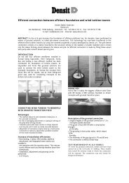
The normal strain ε xx has been plotted in Figure 3<br />
Fig. 3: Plot of ε xx<br />
The shear strain ε xy has been plotted in Figure 4<br />
Fig. 4: Plot of ε xy<br />
Question 3<br />
The bending moment around the z−axis is given as:<br />
M =<br />
∫ h<br />
2<br />
− h 2<br />
∫ h<br />
2<br />
−σ xx y t dy = − −E a y (2l − 2x) y t dy (3)<br />
− h 2<br />
= E t(2l − 2x)a[ 1 3 y3 ] h 2<br />
− h 2<br />
= a(2l − 2x)EI
3<br />
For x = l the bending is 0, and for x = 0 the bending moment is:<br />
M x=0 = 2alEI (4)<br />
and therefore<br />
a = 1 M x=0<br />
2 lEI<br />
Question 4<br />
The resulting shear force on line 2-3 is given as:<br />
(5)<br />
P =<br />
∫ h<br />
2<br />
− h 2<br />
Gγ xy t dy = G t<br />
∫ h<br />
2<br />
− h 2<br />
= G t b 5 4 [y − 1 3 y3 1<br />
(h/2) 2 ] h 2<br />
− h 2<br />
b 5 4 (1 − 1<br />
y2 )dy (6)<br />
(h/2)<br />
2<br />
= G t b 5 4 (h − 1 3 h) = b G 5 6 h t<br />
Question 5<br />
The shear force P and the bending moment have to be in equilibrium which gives:<br />
P = M x=0<br />
l<br />
which gives:<br />
= 2 a EI = b G 5 ht (7)<br />
6<br />
b = 12 5<br />
E I<br />
G<br />
A a (8)<br />
Furthermore we have b =<br />
P<br />
GA k<br />
where the so-called shear area A k = 5A.<br />
6<br />
The vertical displacement in the tip is given by:<br />
v x=l = 1 P l 3<br />
3 EI + P l<br />
(9)<br />
GA k<br />
The last part in the expression is the deformation due to shear, and this part is often very<br />
small and therefore neglected. The shear deformation are most pronounced for relative<br />
short beams or beams with low shear stiness G as in timber.