
You also want an ePaper? Increase the reach of your titles
YUMPU automatically turns print PDFs into web optimized ePapers that Google loves.
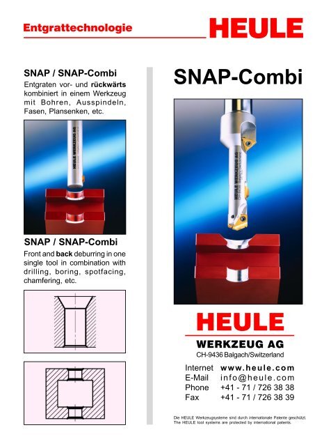
Entgrattechnologie<br />
HEULE<br />
<strong>SNAP</strong> / <strong>SNAP</strong>-<strong>Combi</strong><br />
Entgraten vor- und rückwärts<br />
kombiniert in einem Werkzeug<br />
mit Bohren, Ausspindeln,<br />
Fasen, Plansenken, etc.<br />
<strong>SNAP</strong>-<strong>Combi</strong><br />
<strong>SNAP</strong> / <strong>SNAP</strong>-<strong>Combi</strong><br />
Front and back deburring in one<br />
single tool in combination with<br />
drilling, boring, spotfacing,<br />
chamfering, etc.<br />
HEULE<br />
WERKZEUG AG<br />
CH-9436 Balgach/Switzerland<br />
Internet<br />
E-Mail<br />
Phone<br />
Fax<br />
www.heule.com<br />
info@heule.com<br />
+41 - 71 / 726 38 38<br />
+41 - 71 / 726 38 39<br />
Die HEULE Werkzeugsysteme sind durch internationale Patente geschützt.<br />
The HEULE tool systems are protected by international patents.
1 Werkzeugbeschreibung / Tool description<br />
Pos. Beschreibung Description<br />
1 Grundkörper Tool body<br />
2 Steuerbolzen Control bolt<br />
3 Druckfeder Spring<br />
4 <strong>SNAP</strong> Distanz Stift <strong>SNAP</strong> distance pin<br />
5 Gewinde Stift Set screw<br />
6 <strong>SNAP</strong> Messer <strong>SNAP</strong> blade<br />
7 Bohrplatte Spade drill insert<br />
8 Torx Schraube Torx screw<br />
9 Wendeplatte Indexable insert<br />
10 Torx Schraube Torx screw<br />
Die <strong>SNAP</strong>-Linie ist die Antwort von HEULE auf den<br />
Trend nach immer einfacheren und flexibleren Fertigungslösungen.<br />
Mit dem neuen <strong>SNAP</strong>-System ist es erstmals<br />
gelungen, ein Maximum an Operationen in einem<br />
Werkzeug zusammenzufassen und gleichzeitig einen<br />
hohen Bedienungskomfort zu bewahren.<br />
Praktisch alle denkbaren Bohroperationen, kombiniert<br />
mit dem Entgraten vor- und/oder rückwärts<br />
können nun in einem einfachen und stabilen<br />
Werkzeug zusammengefasst werden.<br />
Wegen der sehr kompakten <strong>SNAP</strong>-Entgratmechanik<br />
verliert das Werkzeug nichts an Stabilität, und es ist<br />
auch problemlos möglich, alle Werkzeuge mit innerer<br />
Kühlmittelzuführung auszurüsten.<br />
Mit der neuen <strong>SNAP</strong>-Technologie wurde ein sehr bedienerfreundliches<br />
Vor- und Rückwärtsentgratsystem<br />
geschaffen.<br />
The <strong>SNAP</strong> product line is HEULE’s answer to the increasing<br />
requirement for simpler and more flexible<br />
manufacturing solutions.<br />
The new <strong>SNAP</strong> system is the first to successfully<br />
allow the combination of a number of operations to be<br />
incorporated into single convenient cycle.<br />
Many drill/chamfering operations can now be completed<br />
in one operation by combining drilling with<br />
front and/or back deburring in one stable and easy<br />
to use tool.<br />
Due to the very compact <strong>SNAP</strong> deburring mechanism<br />
the tool stability is still maintained and tools can be<br />
supplied with or without tool coolant supply.<br />
The simplicity of the design along with the technical<br />
ability of the new <strong>SNAP</strong> system results in a very easy<br />
to use forward and backward deburring system.<br />
V1.0 COMBI<br />
technische Änderungen vorbehalten / subject to technical changes<br />
HEULE WERKZEUG AG / Tel.: +41-71 726 38 38 / Fax: +41-71 726 38 39 Seite / Page 1
Funktion<br />
Ein Entgratmesser wird von einem unter<br />
Federdruck stehenden Steuerbolzen<br />
im Werkzeugkörper beweglich gehalten.<br />
Ein speziell geschliffenes vor- und rückwärts<br />
schneidendes Entgratmesser<br />
schneidet beim Vorwärtsfahren des<br />
Werkzeuges die gewünschte Fase.<br />
Sobald die Fasengrösse erreicht ist,<br />
fährt das Entgratmesser kontinuierlich<br />
in den Werkzeugkörper ein.<br />
Auf einer speziell ausgebildeten Gleitpartie<br />
gleitet das Messer durch die Bohrung,<br />
ohne sie zu verletzen. Auch geriebene<br />
Bohrungen können ohne Beschädigung<br />
durchfahren werden. Beim<br />
Bohrungsaustritt wird das Messer über<br />
eine spezielle Steuernute durch den<br />
Steuerbolzen wieder in Ausgangsstellung<br />
gebracht.<br />
Ohne Spindelstop oder Drehrichtungsänderung<br />
schneidet das Werkzeug<br />
beim Zurückfahren die Rückwärtsfase.<br />
Im Eilgang kann dann das Werkzeug<br />
durch die Bohrung wieder in Ausgangsstellung<br />
gebracht werden.<br />
Eine saubere Entgratung oder Anfasung<br />
vor- und rückseitig ist das Resultat.<br />
Function<br />
The deburring blade is moved in the<br />
tool body via a control bolt returned under<br />
spring pressure.<br />
A specially ground front and back cutting<br />
deburring blade produces the required<br />
chamfer whilst the tool enters<br />
the bore.<br />
Once the chamfer size is attained, the<br />
deburring blade continuously retracts<br />
into the tool body.<br />
On specially designed gliding radii, the<br />
blade passes through the hole without<br />
damaging it. Even reamed bores can<br />
be passed through without any damage.<br />
The deburring blade is equipped<br />
with a special recess which the control<br />
bolt engages and after exiting the hole<br />
brings the blade back into its starting<br />
position.<br />
Linear feed backward facilitates the cutting<br />
of the back chamfer, without the<br />
necessity to stop or change the direction<br />
of spindle rotation. On completion<br />
of the back chamfer the tool can be returned<br />
to the starting position on rapid<br />
feed.<br />
A smooth deburring or chamfering<br />
operation forwards and backwards is<br />
the result of this machining operation.<br />
2 Werkzeugauswahl / Tool selection<br />
1. Werkzeugauswahl:<br />
• Der Bohr-ø bestimmt die Werkzeuggrösse<br />
und die Werkzeugbestell-Nr.<br />
2. Messerauswahl:<br />
• Die Fasengrösse bestimmt das Messer und<br />
die Messerbestell-Nr.<br />
Bestellbeispiel:<br />
Bohr-ø d: 22mm / gewünschte Fase: 0.5x45°<br />
(Fasen-ø D = 23mm)<br />
Werkzeugbestell-Nr.: <strong>SNAP</strong> 20 / ø22.0<br />
1. Tool selection:<br />
• The bore ø determines the tool size and the<br />
tool order No.<br />
2. Blade selection:<br />
• The chamfer size determines the blade and<br />
the blade order No.<br />
Order example:<br />
Bore ø d: 22mm / Required chamfer: 0.5x45°<br />
(Chamfer ø D = 23mm)<br />
Tool order No.: <strong>SNAP</strong> 20 / ø22.0<br />
Messerbestell-Nr.:<br />
GH-Q-M-03172<br />
Blade order No.:<br />
GH-Q-M-03172<br />
Innerhalb einer Werkzeuggrössenfamilie, z.B. <strong>SNAP</strong>8 /<br />
<strong>SNAP</strong>12 / <strong>SNAP</strong>20 ist der Messerquerschnitt gleich. Es<br />
ist somit möglich, alle Messer einer Grössenfamilie in<br />
jedes Werkzeug einzubauen.<br />
Within tool group sizes, e.g. <strong>SNAP</strong>8/<strong>SNAP</strong>12/<strong>SNAP</strong>20<br />
the cross section of the blade is the same. Therefore<br />
all blades of one group can be mounted to each tool<br />
size within that group.<br />
2 Seite / Page<br />
technische Änderungen vorbehalten / subject to technical changes<br />
HEULE WERKZEUG AG / Tel.: +41-71 726 38 38 / Fax: +41-71 726 38 39 COMBI V1.0
3 Messerauswahl / Blade selection<br />
Für die <strong>SNAP</strong>-Linie sind zwei Messertypen erhältlich:<br />
• Messer mit GH-S-Geometrie<br />
• Messer mit DEFA-Geometrie<br />
Für Abmessungen und Bestellnummern siehe Messertabelle<br />
auf den Seiten 17-22.<br />
Two blade types are available for the <strong>SNAP</strong> tool line:<br />
• Blade with GH-S geometry<br />
• Blade with DEFA geometry<br />
For dimensions and order numbers please see blade<br />
table on pages 17-22.<br />
3.1 Messer mit GH-S-Geometrie / Blade with GH-S geometry<br />
Das Messer mit der GH-S-Geometrie ist ein Universalmesser<br />
und wird für fast alle Entgrat- und leichteren<br />
Fasarbeiten verwendet. Auch bei leichten Unebenheiten<br />
kann dieser Messertyp verwendet werden.<br />
Für nur rückwärts schneidende Anwendungen kann<br />
das vor- und rückwärts schneidende Messer eingesetzt<br />
werden. Die vordere Bohrungskante kann im Eilgang<br />
durchfahren werden, ohne dem Werkzeug zu schaden.<br />
Beim langsamen Durchfahren der vorderen Bohrungskante<br />
wird diese entsprechend der Vorschubgeschwindigkeit<br />
angefast.<br />
Nur wenn mit Sicherheit keine Entgratung an der<br />
Vorderseite der Bohrung verursacht werden darf, müssen<br />
nur rückwärts schneidende Messer verwendet<br />
werden.<br />
Messer, siehe Seiten 17-22.<br />
The blade with the GH-S geometry is an universal<br />
blade suitable for most deburring and easy chamfering<br />
operations. This blade type can also be used in applications<br />
where there is slight unevenness on the<br />
surface of the component.<br />
Front and back chamfering is achieved by linear feed<br />
forward and backward and the size of chamfer may be<br />
varied by the relative federate applied. For back cutting<br />
only a front and back cutting blade can be used, by<br />
traversing through the relative hole in rapid feed without<br />
causing damage to either the front edge of the hole<br />
or the tool.<br />
Only when no deburring or chamfering is required on<br />
the front of the hole is it necessary to use back cutting<br />
only blades.<br />
Blades, see pages 17-22.<br />
3.2 Messer mit DEFA-Geometrie / Blade with DEFA geometry<br />
Dieser Messertyp stellt erhöhte Anforderungen an das<br />
Maschinenumfeld, wie z.B. stabile Aufspannung von<br />
Werkstück und Werkzeug sowie eine stabile Maschinenspindel,<br />
etc.<br />
Messer mit dem DEFA-Geometrie werden vor allem<br />
verwendet, wenn eine definierte, tolerierte und über<br />
längere Zeit gleichbleibende Fasengrösse gefordert<br />
wird.<br />
Auf keinen Fall darf mit vor- und rückwärts schneidenden<br />
Messern dieses Typs im Eilgang durch die<br />
Bohrung gefahren werden. Wird keine Vorwärtsfase<br />
gewünscht, muss ein nur rückwärts schneidendes<br />
Messer eingesetzt werden.<br />
Der Vorschub für Messer mit DEFA-Geometrie liegt<br />
bei 0,03 bis 0,1 mm/U. Der obere Wert sollte nicht ü-<br />
berschritten werden.<br />
Messer, siehe Seiten 17-22.<br />
This blade type is responsive to the conditions of the<br />
machine, i.e. stability, clamping of work piece and tool<br />
in addition to stable machine spindle, etc.<br />
The DEFA blade is mainly used when a defined,<br />
toleranced or more consistent chamfer size is<br />
required.<br />
It prohibits the passing of forward and backward cutting<br />
blades through the hole in rapid feed. If no front<br />
chamfer is required, a back cutting only blade has to<br />
be used.<br />
The feed rate for DEFA geometry blades is from 0.03<br />
to 0.1mm/rev. The upper value should not be exceeded<br />
as blade breakage may result.<br />
Blades, see pages 17-22.<br />
V1.0 COMBI<br />
technische Änderungen vorbehalten / subject to technical changes<br />
HEULE WERKZEUG AG / Tel.: +41-71 726 38 38 / Fax: +41-71 726 38 39 Seite / Page 3
4 Bedienung des <strong>SNAP</strong>-Entgratsystems<br />
Instructions for using the <strong>SNAP</strong> deburring system<br />
4.1 Messerwechsel / Changing the blades<br />
1. Messer herausnehmen / Blade removal<br />
1. 2.<br />
Das <strong>SNAP</strong> Messer wird mit einem stumpfen Gegenstand (z.B. kleiner Schraubenzieher) durchs Werkzeug hindurchgedrückt.<br />
Der Schraubenzieher wird am Messerkopf (1) angesetzt.<br />
The <strong>SNAP</strong> blade can be pushed through the tool with an edgeless object (e.g. small screw driver). The screw driver<br />
is put on at the blade head (1).<br />
2. Messer einsetzen / Inserting the blade<br />
1. 2.<br />
Das Entgratmesser wird mit dem Messerrücken (3) voran in die Messerausnehmung (Messerfenster) gedrückt, bis<br />
es einschnappt. Es ist darauf zu achten, dass die Steuernute (2) in Richtung Werkzeugschaft (Steuerbolzen) zeigt.<br />
Das Messer kann von beiden Seiten her ins Werkzeug eingesetzt werden.<br />
Das Werkzeug ist wieder einsatzbereit.<br />
The deburring blade is pushed with its back (3) first into the blade recess (blade window) of the tool until it engages.<br />
Please make sure it is aligned with the groove (2) in the direction of the tool shank.<br />
The blade can be inserted into the tool from both sides.<br />
The tool is now ready for operation.<br />
4 Seite / Page<br />
technische Änderungen vorbehalten / subject to technical changes<br />
HEULE WERKZEUG AG / Tel.: +41-71 726 38 38 / Fax: +41-71 726 38 39 COMBI V1.0
4.1.1 Einstellen der Messerkraft / Setting the blade force<br />
Mit dem Gewindestift (5) hinten im Schaft, kann die<br />
Messerkraft verstellt werden.<br />
Schraube hineindrehen (rechts drehen):<br />
⇒ stärkere Messerkraft<br />
Die Messerkraft soll so stark eingestellt werden, dass<br />
das Messer auch bei Verschmutzung noch sicher<br />
herausfährt.<br />
Bei Messern mit DEFA-Geometrie hat eine Veränderung<br />
der Messerkraft keinen Einfluss auf die Fasengrösse<br />
(siehe 3.2, 4.3.2).<br />
Bei Messern mit GH-S-Geometrie soll je nach Werkstoff<br />
(Stahl, Alu), gewünschter Entgrat- oder Fasgrösse<br />
und Schnittwerten (Vorschub), die Messerkraft angepasst<br />
werden.<br />
Bei Messern mit GH-S-Geometrie kann über die<br />
Messerkraft die Fasengrösse nur leicht variiert werden.<br />
Mit dem idealen Messerdruck kann die Entgratung<br />
oder Fasqualität verbessert werden. Ebenfalls die<br />
Standzeit des Messers.<br />
Wird aus bestimmten Gründen eine sehr grosse<br />
Messerkraft benötigt, kann bei der <strong>SNAP</strong>8 und<br />
<strong>SNAP</strong>12 Familie, die härtere Druckfeder GH-H-F-0011<br />
eingebaut werden (nicht Standard).<br />
Beim Einschrauben des Gewindeteiles (5) können ca.<br />
folgende Messerkräfte eingestellt werden:<br />
The blade force can be adjusted with the set screw (5)<br />
in rear of the shank.<br />
Screw in set screw (turn clockwise)<br />
⇒ increased blade force<br />
The blade force has to be sufficient to enable the<br />
blade to extend outwards in the event of swarf<br />
ingress.<br />
Changing the blade force of DEFA blades does not<br />
influence the chamfer size (see 3.2, 4.3.2).<br />
Using blades having the GH-S cutting geometry, it is<br />
recommended to adjust the blade force depending on<br />
the material (steel, alu), chamfer-size or cutting values<br />
(feed).<br />
By changing the blade force of GH-S blades (standard)<br />
the chamfer size can be minimal adjusted only.<br />
Working with the correct blade pressure increases the<br />
blade life and improves the chamfer quality.<br />
If a very strong blade force is required, a harder<br />
spring can be inserted into the tools of <strong>SNAP</strong>8 and<br />
<strong>SNAP</strong>12 groups (not standard).<br />
By tensioning the set screw (5) the following blade<br />
forces can be set:<br />
Bohr-ø<br />
Einschraub<br />
-tiefe<br />
t in mm<br />
Messerkraft in N<br />
Bore ø<br />
Screw<br />
depth<br />
t in mm<br />
Blade force in N<br />
GH-S- DEFA-<br />
GH-S<br />
d<br />
Geometrie Geometrie<br />
d<br />
geometry<br />
bis 0 8 6 up to 0 8 6<br />
20.0mm 5 14 9 20.0mm 5 14 9<br />
10 20 12 10 20 12<br />
ab 0 16 12 above 0 16 12<br />
20.0mm 5 23 16 20.0mm 5 23 16<br />
10 30 20 10 30 20<br />
DEFA<br />
geometry<br />
V1.0 COMBI<br />
technische Änderungen vorbehalten / subject to technical changes<br />
HEULE WERKZEUG AG / Tel.: +41-71 726 38 38 / Fax: +41-71 726 38 39 Seite / Page 5
4.2 <strong>SNAP</strong> Schnittdaten / <strong>SNAP</strong> cutting data<br />
4.2.1 <strong>SNAP</strong> Messer mit GH-S-Geometrie / <strong>SNAP</strong> blade with GH-S geometry<br />
Richtwerte / Standard values<br />
Werkstoff Schnittgeschwindigkeit v (m/min.) bei Vorschub s (mm/U)<br />
Material Cutting speed v (m/min.) for Feed s (mm/rev.)<br />
HM HM TiN HM TiAlN<br />
carbide carbide TiN carbide TiAlN<br />
Stahl, Stahllegierungen<br />
Steel, steel alloys<br />
Guss, Gusseisenwerkstoffe<br />
Cast, cast iron materials<br />
Nichteisen-Metalle<br />
Non-ferrous metals<br />
45 - 65 45 - 70 45 - 70 0.1 - 0.2<br />
45 - 65 45 - 70 45 - 70 0.1 - 0.3<br />
65 - 105 65 - 120 65 - 120 0.1 - 0.3<br />
4.2.2 <strong>SNAP</strong> Messer mit DEFA-Geometrie / <strong>SNAP</strong> blade with DEFA geometry<br />
Richtwerte / Standard values<br />
Werkstoff Schnittgeschwindigkeit v (m/min.) bei Vorschub s (mm/U)<br />
Material Cutting speed v (m/min.) for Feed s (mm/rev.)<br />
HM HM TiN HM TiAlN<br />
carbide carbide TiN carbide TiAlN<br />
Stahl, Stahllegierungen<br />
Steel, steel alloys<br />
Guss, Gusseisenwerkstoffe<br />
Cast, cast iron materials<br />
Nichteisen-Metalle<br />
Non-ferrous metals<br />
45 - 65 45 - 70 45 - 70<br />
45 - 65 45 - 70 45 - 70 0.03 - 0.1<br />
65 - 105 65 - 120 65 - 120<br />
4.3 Einstellen der Fasengrösse / Setting the chamfer size<br />
4.3.1 <strong>SNAP</strong> Messer mit GH-S-Geometrie / <strong>SNAP</strong> blade with GH-S geometry<br />
Die Fasengrösse wird grundsätzlich durch das<br />
gewählte Messer (Messerlänge) bestimmt. Jedes<br />
Messer erzeugt eine bestimmte Fasengrösse.<br />
Die maximal erreichbare Fasgrösse wird durch den<br />
max. Fasdurchmesser D bestimmt (siehe Messertabelle<br />
Seiten 17-22).<br />
Die maximal erzeugbare Fase liegt je nach Werkzeuggrösse<br />
zwischen 0.5 und 1.5mm.<br />
The chamfer size is basically determinded by the<br />
blade (length of blade). Each blade creates a<br />
specific chamfer size.<br />
The maximum possible chamfer size is determined<br />
by the maximum chamfer diameter D (see<br />
blade table pages 17-22).<br />
The maximum possible chamfer is between 0.5<br />
and 1.5mm, depending on the tool size.<br />
Über die Federkraft (siehe 4.1.1.) kann das Werkzeug<br />
an das zu bearbeitende Material angepasst<br />
werden. Ebenfalls kann über den idealen Messerdruck<br />
die Entgrat- oder Fasqualität verbessert werden.<br />
By changing the blade force (4.1.1) you can<br />
adapt the tool according to the work piece material.<br />
A good tool set up (blade force) is increasing<br />
the deburr- or chamfering result.<br />
6 Seite / Page<br />
technische Änderungen vorbehalten / subject to technical changes<br />
HEULE WERKZEUG AG / Tel.: +41-71 726 38 38 / Fax: +41-71 726 38 39 COMBI V1.0
4.3.2 <strong>SNAP</strong> Messer mit DEFA-Geometrie / <strong>SNAP</strong> blade with DEFA geometry<br />
Die Fasengrösse bei <strong>SNAP</strong> Messern mit DEFA-<br />
Geometrie wird ausschliesslich über den Fasendurchmesser<br />
der Messertabelle bestimmt. D.h.,<br />
weder über den Vorschub noch über die Messerkraft<br />
kann die Fasengrösse verändert werden. Der Vorschub<br />
für diesen Messertyp sollte zwischen 0,03<br />
und 0,1mm/U liegen. Die Messerkraft muss nur so<br />
stark eingestellt werden, dass das Messer auch bei<br />
Verschmutzung noch sicher ausfährt.<br />
The chamfer size of <strong>SNAP</strong> blades with DEFA<br />
geometry is solely determined by the chamfer<br />
diameter (see blade table). This means that neither<br />
changing the feed rate nor changing the blade<br />
force has an effect on the chamfer size. The feed<br />
rate for this blade type should be between 0.03<br />
and 0.1mm/rev. The blade force has to be<br />
sufficient to ensure that the blade extends<br />
outwards in the event of swarf ingress.<br />
4.4 Schnittgeschwindigkeiten für HSS Bohrplatten<br />
Cutting speed for HSS spade drill inserts<br />
Richtwerte Brinellhärte HSS TiN HSS TiAlN Vorschub s (mm/U)<br />
Bohr-ø d<br />
Standard values Brinell<br />
hardness<br />
HSS TiN HSS TiAlN Feed s (mm/rev.)<br />
Bore ø d<br />
m/min. m/min. 9.5-12.5 13-17 18-24 25-35<br />
leicht spanbarer Stahl 100 - 150 61 85 0.18 0.25 0.33 0.33<br />
free machining steel 150 - 200 55 79 0.18 0.25 0.33 0.33<br />
200 - 250 49 73 0.15 0.25 0.33 0.33<br />
weicher Stahl 85 - 125 52 76 0.15 0.23 0.30 0.30<br />
low carbon steel 125 - 175 49 73 0.15 0.23 0.30 0.30<br />
175 - 225 46 69 0.13 0.20 0.25 0.25<br />
normaler Stahl 125 - 175 49 73 0.15 0.23 0.30 0.30<br />
medium carbon steel 175 - 225 46 69 0.13 0.20 0.25 0.25<br />
225 - 275 43 64 0.13 0.20 0.25 0.25<br />
legierter Stahl 125 - 175 46 64 0.15 0.20 0.25 0.25<br />
alloy steel 175 - 225 43 59 0.13 0.20 0.25 0.25<br />
225 - 275 40 55 0.13 0.18 0.25 0.25<br />
hochfeste Legierung 225 - 300 24 33 0.13 0.18 0.23 0.23<br />
high strength alloy 300 - 350 18 26 0.10 0.18 0.23 0.23<br />
Baustahl 100 - 150 43 61 0.15 0.25 0.30 0.30<br />
structural steel 150 - 250 37 52 0.13 0.23 0.25 0.25<br />
Hochtemperaturlegierung 140 - 220 9 12 0.08 0.18 0.20 0.20<br />
high temp. alloy 220 - 310 8 11 0.08 0.15 0.18 0.18<br />
rostfreier Stahl 135 - 185 23 32 0.08 0.18 0.20 0.20<br />
stainless steel 185 - 275 18 27 0.08 0.15 0.18 0.18<br />
Werkzeugstahl 150 - 200 24 33 0.10 0.15 0.20 0.20<br />
tool steel 200 - 250 18 27 0.10 0.15 0.20 0.20<br />
Aluminium 30 183 260 0.20 0.33 0.41 0.41<br />
aluminium 180 91 137 0.20 0.33 0.41 0.41<br />
Gusseisen 120 - 150 52 76 0.18 0.30 0.41 0.41<br />
cast iron/S.G. iron 150 - 200 46 69 0.15 0.28 0.36 0.36<br />
200 - 220 40 59 0.15 0.23 0.30 0.30<br />
V1.0 COMBI<br />
technische Änderungen vorbehalten / subject to technical changes<br />
HEULE WERKZEUG AG / Tel.: +41-71 726 38 38 / Fax: +41-71 726 38 39 Seite / Page 7
4.5 Schnittgeschwindigkeiten für HM Bohrplatten<br />
Cutting speed for carbide spade drill inserts<br />
Richtwerte Brinellhärte HM-Sorte TiN<br />
m/min.<br />
Standard values Brinell carbide TiN<br />
hardness grade m/min.<br />
Vorschub s (mm/U)<br />
Bohr-ø d<br />
Feed s (mm/rev.)<br />
Bore ø d<br />
9.5-12.5 13-17 18-24 25-35<br />
leicht spanbarer Stahl 100 - 150 96 0.15 0.23 0.30 0.30<br />
free machining steel 150 - 200 P40 85 0.15 0.20 0.28 0.28<br />
200 - 250 79 0.13 0.20 0.25 0.25<br />
weicher Stahl 85 - 125 91 0.15 0.20 0.25 0.25<br />
low carbon steel 125 - 175 P40 79 0.13 0.20 0.25 0.25<br />
175 - 225 73 0.10 0.18 0.20 0.20<br />
normaler Stahl 125 - 175 79 0.13 0.20 0.25 0.25<br />
medium carbon steel 175 - 225 P40 73 0.13 0.18 0.20 0.20<br />
225 - 275 67 0.10 0.18 0.20 0.20<br />
legierter Stahl 125 - 175 76 0.13 0.20 0.25 0.25<br />
alloy steel 175 - 225 P40 70 0.13 0.18 0.23 0.23<br />
225 - 275 64 0.10 0.18 0.23 0.23<br />
hochfeste Legierung 225 - 300 P40 49 0.13 0.18 0.20 0.20<br />
high strength alloy 300 - 350 43 0.10 0.15 0.18 0.18<br />
Baustahl 100 - 150 P40 73 0.15 0.25 0.28 0.28<br />
structural steel 150 - 250 61 0.13 0.20 0.23 0.23<br />
Hochtemperaturlegierung 140 - 220 K20 24 0.08 0.15 0.18 0.18<br />
high temp. alloy 220 - 310 18 0.08 0.13 0.15 0.15<br />
rostfreier Stahl 135 - 185 K20 49 0.15 0.20 0.23 0.23<br />
stainless steel 185 - 275 37 0.13 0.18 0.20 0.20<br />
Werkzeugstahl 150 - 200 P40 49 0.08 0.13 0.18 0.18<br />
tool steel 200 - 250 37 0.08 0.13 0.18 0.18<br />
Aluminium 30 K20 366 0.20 0.33 0.41 0.41<br />
Aluminium 180 244 0.18 0.28 0.36 0.36<br />
Gusseisen 120 - 150 98 0.15 0.23 0.28 0.28<br />
cast iron/S.G. iron 150 - 200 K20 82 0.13 0.20 0.25 0.25<br />
200 - 220 73 0.13 0.18 0.20 0.20<br />
8 Seite / Page<br />
technische Änderungen vorbehalten / subject to technical changes<br />
HEULE WERKZEUG AG / Tel.: +41-71 726 38 38 / Fax: +41-71 726 38 39 COMBI V1.0
4.6 <strong>SNAP</strong> Bohrkombi / <strong>SNAP</strong> Drill <strong>Combi</strong><br />
Bei der ganzen Bearbeitung ist keine Drehrichtungsänderung<br />
oder Stillstand der Spindel nötig.<br />
AV: Arbeitsvorschub, AR: Arbeitsvorschub,<br />
vorwärts<br />
rückwärts<br />
EV: Eilvorschub, ER: Eilvorschub,<br />
vorwärts<br />
rückwärts<br />
1. EV<br />
Das Werkzeug wird im EV<br />
bis vor das Werkstück<br />
positioniert.<br />
Sicherheitsabstand<br />
beachten!<br />
1. EV<br />
Rapid traverse of the tool to<br />
just above the top of the<br />
work piece.<br />
Note: Clearance distance.<br />
It is not necessary to change the direction of rotation or<br />
stop the spindle.<br />
AV: Working feed, AR: Working feed,<br />
forward<br />
backward<br />
EV: Rapid feed, ER: Rapid feed,<br />
forward<br />
backward<br />
4. AV<br />
Im AV wird die Fase erstellt.<br />
Es wird so lange im AV<br />
gefahren, bis das Messer<br />
ganz in das Werkzeug<br />
eingefahren ist.<br />
4. AV<br />
In linear feed forward<br />
(AV) the chamfer is<br />
generated. Continue in<br />
working feed until the<br />
blade is completely<br />
retracted into the tool.<br />
2. AV<br />
Im AV wird die Bohrung<br />
erstellt. Es wird solange<br />
im AV gefahren, bis vollständig<br />
durchgebohrt ist.<br />
5. EV<br />
Im EV kann soweit durch<br />
die Bohrung gefahren<br />
werden, bis das <strong>SNAP</strong>-<br />
Messer wieder vollständig<br />
frei ist und ausfahren kann.<br />
2. AV<br />
In forward linear feed the<br />
bore is produced. Continue<br />
in linear feed until the spade<br />
drill insert is completely clear<br />
of the bore.<br />
3. EV<br />
Im EV das Werkzeug mit<br />
dem <strong>SNAP</strong>-Messer bis<br />
kurz vor die Bohrungsbzw.<br />
mögliche Gratkante<br />
positionieren.<br />
3. EV<br />
Position tool with <strong>SNAP</strong><br />
blade in rapid feed, forward<br />
slightly above the top<br />
material surface of bore<br />
or burr.<br />
5. EV<br />
The tool can be passed<br />
through the bore in rapid<br />
feed forward until the<br />
<strong>SNAP</strong> blade clears<br />
the hole and is fully<br />
extended.<br />
6. AR / ER<br />
Die Rückwärtsfase wird<br />
im AR geschnitten (keine<br />
Drehrichtungsänderung).<br />
Sobald das <strong>SNAP</strong>-Messer<br />
vollständig ins Werkzeug<br />
eingefahren ist, kann im<br />
ER aus der Bohrung<br />
gefahren werden.<br />
6. AR / ER<br />
The back chamfer is<br />
machined by linear feed<br />
backward (no change of<br />
spindle rotation). As soon<br />
as the <strong>SNAP</strong> blade is<br />
completely retracted into<br />
the tool, the tool can travel<br />
out of the hole in rapid<br />
feed backward ER.<br />
V1.0 COMBI<br />
technische Änderungen vorbehalten / subject to technical changes<br />
HEULE WERKZEUG AG / Tel.: +41-71 726 38 38 / Fax: +41-71 726 38 39 Seite / Page 9
4.7 <strong>SNAP</strong> Bohrsenkkombi / <strong>SNAP</strong> Drill Counterbore <strong>Combi</strong><br />
Bei der ganzen Bearbeitung ist keine Drehrichtungsänderung<br />
oder Stillstand der Spindel nötig.<br />
AV: Arbeitsvorschub, AR: Arbeitsvorschub,<br />
vorwärts<br />
rückwärts<br />
EV: Eilvorschub, ER: Eilvorschub,<br />
vorwärts<br />
rückwärts<br />
1. EV<br />
Das Werkzeug wird im<br />
EV bis vor das Werkstück<br />
positioniert.<br />
Sicherheitsabstand<br />
beachten!<br />
1. EV<br />
Rapid traverse of the tool<br />
to just above the top of<br />
the work piece.<br />
Note: Clearance distance.<br />
2. AV<br />
Im AV wird die Bohrung<br />
erstellt. Es wird so lange<br />
im AV gefahren, bis vollständig<br />
durchgebohrt ist.<br />
2. AV<br />
In forward linear feed the<br />
bore is produced. Continue<br />
in linear feed until<br />
the spade drill insert is<br />
completely clear of the<br />
bore.<br />
3. EV<br />
Im EV das Werkzeug mit<br />
der Wendeplatte bis kurz<br />
vor die Bohrungs- bzw.<br />
mögliche Gratkante<br />
positionieren.<br />
It is not necessary to change the direction of rotation or<br />
stop the spindle.<br />
AV: Working feed, AR: Working feed,<br />
forward<br />
backward<br />
EV: Rapid feed, ER: Rapid feed,<br />
forward<br />
backward<br />
4. AV<br />
Im AV wird die Fase<br />
erstellt. Es wird so tief<br />
im AV gefahren, bis die<br />
gewünschte Fasengrösse<br />
erreicht ist.<br />
4. AV<br />
In linear feed forward (AV)<br />
the chamfer is<br />
generated. Continue<br />
in linear feed until the required<br />
chamfer size is<br />
reached.<br />
5. (ER) / AR<br />
Wenn nötig im (ER)<br />
soweit zurückfahren, bis<br />
das <strong>SNAP</strong>-Messer kurz<br />
vor der Bohrungskante<br />
steht. Die Rückwärtsfase<br />
wird im AR geschnitten<br />
(keine Drehrichtungsänderung).<br />
5. (ER) / AR<br />
If necessary, travel back<br />
in (ER) until the <strong>SNAP</strong><br />
blade is positioned<br />
slightly above bore edge.<br />
The back chamfer is<br />
machined in working<br />
feed backward AR<br />
(no change of spindle<br />
rotation).<br />
6. ER<br />
Sobald das <strong>SNAP</strong>-Messer<br />
vollständig ins Werkzeug<br />
eingefahren ist, kann im<br />
ER aus der Bohrung<br />
gefahren werden.<br />
3. EV<br />
Position tool with indexabalbe<br />
insert in rapid<br />
feed, forward slightly<br />
above the top material<br />
surface of hole or burr.<br />
6. ER<br />
As soon as the <strong>SNAP</strong><br />
blade is completely<br />
retracted into the tool,<br />
the tool can travel out<br />
of the bore in rapid<br />
feed backward ER.<br />
10 Seite / Page<br />
technische Änderungen vorbehalten / subject to technical changes<br />
HEULE WERKZEUG AG / Tel.: +41-71 726 38 38 / Fax: +41-71 726 38 39 COMBI V1.0
5 <strong>SNAP</strong> Bohrkombi / <strong>SNAP</strong> Drill <strong>Combi</strong><br />
5.1 <strong>SNAP</strong>8 Bohrkombi ø9.5-12.0 mit innerer Kühlmittelzuführung<br />
<strong>SNAP</strong>8 Drill <strong>Combi</strong> ø9.5-12.0 with through-tool coolant supply<br />
Max. Fas-ø D = min. Bohr-ø d + 1.5mm<br />
Max. chamfer ø D = min. bore ø + 1.5mm<br />
Ersatzteile / Spare parts:<br />
Pos. Beschreibung Description Best.Nr. Order No.<br />
2 Steuerbolzen ø1.5 Control bolt ø1,5 GH-Q-E-0002<br />
3 Druckfeder ø3.7xø0.5x48 Spring ø3.7xø0.5x48 GH-H-F-0007<br />
5 Gew. Stift M5x8 DIN 913 Set screw M5x8 DIN 913 GH-H-S-0119<br />
Schlüssel zu Pos. 5* Wrench for pos. 5* GH-H-S-2100<br />
6 <strong>SNAP</strong> Messer, siehe Seiten 17-22 <strong>SNAP</strong> blade, see pages 17-22<br />
7 Bohrplatte, siehe Seite 24 Spade drill insert, see page 24<br />
ø d = 9.5-11.0 Torx Schraube M2x4 T6 Torx screw M2x4 T6 GH-H-S-0070<br />
8 ø d = 11.0-12.0 Torx Schraube M2x4.7 T6 Torx screw M2x4.7 T6 GH-H-S-0071<br />
Schlüssel zu Pos. 8* Wrench for pos. 8* GH-H-S-2000<br />
*Schlüssel zu Pos. 5 / Pos. 8 nicht im Lieferumfang enthalten<br />
Bore<br />
depth<br />
Bohrtiefe<br />
Bohrungsbereich<br />
Bore<br />
range<br />
Fas-ø<br />
bereich<br />
Chamferø<br />
range<br />
Pos. 1 Pos. 4<br />
Grund- Distanz<br />
körper Stift<br />
Best. Nr. Best. Nr.<br />
Tool<br />
body<br />
Order No.<br />
Distance<br />
pin<br />
Order No.<br />
*Wrenches for pos. 5 / pos. 8: to be ordered separately<br />
Werkzeug ohne Messer, ohne Bohrplatte<br />
Tool without blade, without spade drill insert<br />
T ø d ø D GH-Q-G- GH-Q-E- ø D1 X X1 LN L1 ø DS L GH-Q-O-<br />
9.5-10.2 10.0-11.5 3440 9.4 2.30 3440<br />
6.0 10.2-11.0 10.5-12.5 3444 0020 10.0 15.3 2.45 12.0 91.3 20 50 3444<br />
11.1-12.0 11.5-13.5 3448 10.8 2.70 3448<br />
9.5-10.2 10.0-11.5 3441 9.4 2.30 3441<br />
12.0 10.2-11.0 10.5-12.5 3445 0021 10.0 21.3 2.45 17.0 102.3 20 50 3445<br />
11.1-12.0 11.5-13.5 3449 10.8 2.70 3449<br />
9.5-10.2 10.0-11.5 3442 9.4 2.30 3442<br />
18.0 10.2-11.0 10.5-12.5 3446 0022 10.0 27.3 2.45 22.0 113.3 20 50 3446<br />
11.1-12.0 11.5-13.5 3450 10.8 2.70 3450<br />
9.5-10.2 10.0-11.5 3443 9.4 2.30 3443<br />
24.0 10.2-11.0 10.5-12.5 3447 0023 10.0 33.3 2.45 27.0 124.3 20 50 3447<br />
11.1-12.0 11.5-13.5 3451 10.8 2.70 3451<br />
Best.<br />
Nr.<br />
Order<br />
No.<br />
Für WZ oder Grundkörper mit Weldon-(HB) od. Whistle-Notch-<br />
Schaft (HE), zur Best. Nr. -HB od. -HE hinzufügen.<br />
Bestellbeispiel:<br />
<strong>SNAP</strong>8 Bohrkombi ø10.0 / T=6.0mm mit Weldonschaft<br />
Best. Nr.: GH-Q-O-3440-HB<br />
For tools or tool bodies with weldon shank (HB) or whistle notch<br />
shank (HE), add -HB or -HE to the order No.<br />
For example:<br />
<strong>SNAP</strong>8 Drill <strong>Combi</strong> ø10.0 / T=6.0mm with weldon shank<br />
Order No.: GH-Q-O-3440-HB<br />
V1.0 COMBI<br />
technische Änderungen vorbehalten / subject to technical changes<br />
HEULE WERKZEUG AG / Tel.: +41-71 726 38 38 / Fax: +41-71 726 38 39 Seite / Page 11
5.2 <strong>SNAP</strong>12 Bohrkombi ø12.0-20.0 mit innerer Kühlmittelzuführung<br />
<strong>SNAP</strong>12 Drill <strong>Combi</strong> ø12.0-20.0 with through-tool coolant supply<br />
Max. Fas-ø D = min. Bohr-ø d + 2.0mm<br />
Max. chamfer ø D = min. bore ø d + 2.0mm<br />
Ersatzteile / Spare parts:<br />
Pos. Beschreibung Description Best.Nr. Order No.<br />
2 Steuerbolzen ø1.5 Control bolt ø1,5 GH-Q-E-0002<br />
3 Druckfeder ø3.7xø0.5x48 Spring ø3.7xø0.5x48 GH-H-F-0007<br />
5 Gew. Stift M5x8 DIN 913 Set screw M5x8 DIN 913 GH-H-S-0119<br />
Schlüssel zu Pos. 5* Wrench for pos. 5* GH-H-S-2100<br />
6 <strong>SNAP</strong> Messer, siehe Seiten 17-22 <strong>SNAP</strong> blade, see pages 17-22<br />
7 Bohrplatte, siehe Seite 24 Spade drill insert, see page 24<br />
8(a) ø d = 12.0-13.0 Torx Schraube M2x4.7 T6 Torx screw M2x4.7 T6 GH-H-S-0071<br />
Schlüssel zu Pos. 8(a)* Wrench for pos. 8(a)* GH-H-S-2000<br />
8(b) ø d = 13.0-15.0 Torx Schraube M2.5x 5.6 T7 Torx screw M2.5x5.6 T7 GH-H-S-0066<br />
ø d = 15.0-17.8 Torx Schraube M2.5x6.75 T7 Torx screw M2.5x6.75 T7 GH-H-S-0067<br />
Schlüssel zu Pos. 8(b)* Wrench for pos. 8(b)* GH-H-S-2001<br />
8(c) ø d = 17.8-20.0 Torx Schraube M3.0x7.5 T9 Torx screw M3.0x7.5 T9 GH-H-S-0068<br />
Schlüssel zu Pos. 8(c)* Wrench for pos. 8(c)* GH-H-S-2003<br />
*Schlüssel zu Pos. 5 / Pos. 8 nicht im Lieferumfang enthalten<br />
Pos. 1 Pos. 4<br />
Grundkörper<br />
Distanz<br />
Stift<br />
Best. Nr. Best. Nr.<br />
Boredepth<br />
Bore<br />
range<br />
Fas-ø<br />
bereich<br />
Chamferø<br />
range<br />
Bohrtiefe<br />
Bohrungsbereich<br />
Tool<br />
body<br />
Order No.<br />
Distance<br />
pin<br />
Order No.<br />
*Wrenches for pos. 5 / pos. 8: to be ordered separately<br />
Werkzeug ohne Messer, ohne Bohrplatte<br />
Tool without blade, without spade drill<br />
T ø d ø D GH-Q-G- GH-Q-E- ø D1 X X1 LN L1 ø DS L GH-Q-O-<br />
7.0 12.0-12.9 12.5-15.0 3452 0020 11.8 17.3 2.9 13 92.8 3452<br />
9.0 13.0-15.0 13.5-17.0 3456 0020 12.8 19.8 3.3 13 95.3 20 50 3456<br />
10.0 15.0-17.6 15.5-19.5 3460 0021 14.8 21.8 4.0 19 102.8 3460<br />
10.0 17.7-20.0 19.5-22.0 3464 0021 17.5 24.6 4.4 12 105.6 25 56 3464<br />
14.0 12.0-12.9 12.5-15.0 3453 0021 11.8 24.3 2.9 18 104.8 3453<br />
16.0 13.0-15.0 13.5-17.0 3457 0021 12.8 26.8 3.3 18 107.3 20 50 3457<br />
18.0 15.0-17.6 15.5-19.5 3461 0022 14.8 29.8 4.0 24 115.8 3461<br />
20.0 17.7-20.0 19.5-22.0 3465 0023 17.5 34.6 4.4 22 125.6 25 56 3465<br />
21.0 12.0-12.9 12.5-15.0 3454 0022 11.8 31.3 2.9 23 116.8 3454<br />
23.0 13.0-15.0 13.5-17.0 3458 0022 12.8 33.8 3.3 23 119.3 20 50 3458<br />
26.0 15.0-17.6 15.5-19.5 3462 0023 14.8 37.8 4.0 29 128.8 3462<br />
30.0 17.7-20.0 19.5-22.0 3466 0025 17.5 44.6 4.4 32 145.6 25 56 3466<br />
28.0 12.0-12.9 12.5-15.0 3455 0023 11.8 38.3 2.9 28 128.8 3455<br />
30.0 13.0-15.0 13.5-17.0 3459 0024 12.8 40.8 3.3 33 136.3 20 50 3459<br />
34.0 15.0-17.6 15.5-19.5 3463 0025 14.8 45.8 4.0 39 146.8 3463<br />
40.0 17.7-20.0 19.5-22.0 3467 0027 17.5 54.6 4.4 42 165.6 25 56 3467<br />
Best.<br />
Nr.<br />
Order<br />
No.<br />
Für WZ oder Grundkörper mit Weldon-(HB) od.Whistle-Notch-<br />
Schaft (HE), zur Best. Nr. -HB od. -HE hinzufügen.<br />
For tools or tool bodies with weldon shank (HB) or whistle<br />
notch shank (HE), add -HB or -HE to the order No.<br />
12 Seite / Page<br />
technische Änderungen vorbehalten / subject to technical changes<br />
HEULE WERKZEUG AG / Tel.: +41-71 726 38 38 / Fax: +41-71 726 38 39 COMBI V1.0
5.3 <strong>SNAP</strong>20 Bohrkombi ø20.0-35.0 mit innerer Kühlmittelzuführung<br />
<strong>SNAP</strong>20 Drill <strong>Combi</strong> ø20.0-35.0 with through-tool coolant supply<br />
Max. Fas-ø D = min. Bohr-ø d + 3.0mm<br />
Max. chamfer ø D = min. bore ø d + 3.0mm<br />
Ersatzteile / Spare parts:<br />
Pos. Beschreibung Description Best. Nr. Order No.<br />
2 Steuerbolzen ø2.5 Control bolt ø2,5 GH-Q-E-0003<br />
3 Druckfeder ø4.3xø0.6x48 Spring ø4.3xø0.6x52 GH-H-F-0011<br />
5 Gew. Stift M5x8 DIN 913 Set screw M5x8 DIN 913 GH-H-S-0119<br />
Schlüssel zu Pos. 5* Wrench for pos. 5* GH-H-S-2100<br />
6 <strong>SNAP</strong> Messer, siehe Seiten 17-22 <strong>SNAP</strong> blade, see pages 17-22<br />
7 Bohrplatte, siehe Seite 24 Spade drill insert, see page 24<br />
8(a) ø d = 20.0-24.0 Torx Schraube M3x 9 T9 Torx screw M3x9 T9 GH-H-S-0069<br />
Schlüssel zu Pos. 8(a)* Wrench for pos. 8(a)* GH-H-S-2003<br />
8(b) ø d = 24.0-35.0 Torx Schraube M4x9.5 T15 Torx screw M4x9.5 T15 GH-H-S-0072<br />
Schlüssel zu Pos. 8(b)* Wrench for pos. 8(b)* GH-H-S-2005<br />
*Schlüssel zu Pos. 5 / Pos. 8 nicht im Lieferumfang enthalten<br />
Bohrtiefe<br />
Bore<br />
depth<br />
Bohrungsbereich<br />
Bore<br />
range<br />
Fas-ø<br />
bereich<br />
Chamferø<br />
range<br />
Pos. 1 Pos. 4<br />
Grund- Distanz<br />
körper Stift<br />
Best. Nr. Best. Nr.<br />
Tool<br />
body<br />
Order No.<br />
Distance pin<br />
Order No.<br />
*Wrenches for pos. 5 / pos. 8: to be ordered separately<br />
Werkzeug ohne Messer, ohne Bohrplatte<br />
Tool without blade, without spade drill insert<br />
T ø d ø D GH-Q-G- GH-Q-E- ø D1 X X1 LN L1 ø DS L GH-Q-O-<br />
12.0 20.0-24.3 21.0-27.0 3468 19.8 27.6 5.3 23 119.6 25 56 3468<br />
15.0 24.4-30.0 25.0-33.0 3472 0022 24.2 33.6 6.6 17 125.6 32 60 3472<br />
20.0 30.0-35.0 31.0-38.0 3476 29.8 41.6 7.8 20 133.6 32 60 3476<br />
24.0 20.0-24.3 21.0-27.0 3469 0023 19.8 39.6 5.3 28 136.6 25 56 3469<br />
30.0 24.4-30.0 25.0-33.0 3473 0025 24.2 48.6 6.6 32 155.6 32 60 3473<br />
38.0 30.0-35.0 31.0-38.0 3477 0026 29.8 59.6 7.8 40 171.6 32 60 3477<br />
36.0 20.0-24.3 21.0-27.0 3470 0025 19.8 51.6 5.3 38 158.6 25 56 3470<br />
45.0 24.4-30.0 25.0-33.0 3474 0028 24.2 63.6 6.6 47 185.6 32 60 3474<br />
56.0 30.0-35.0 31.0-38.0 3478 0029 29.8 77.6 7.8 55 204.6 32 60 3478<br />
48.0 20.0-24.3 21.0-27.0 3471 0027 19.8 63.6 5.3 48 180.6 25 56 3471<br />
60.0 24.4-30.0 25.0-33.0 3475 0031 24.2 78.6 6.6 62 215.6 32 60 3475<br />
74.0 30.0-35.0 31.0-38.0 3479 0033 29.8 95.6 7.8 75 242.6 32 60 3479<br />
Best.<br />
Nr.<br />
Order<br />
No.<br />
Für WZ oder Grundkörper mit Weldon-(HB) od. Whistle-Notch-<br />
Schaft (HE), zur Best. Nr. -HB od. -HE hinzufügen.<br />
Bestellbeispiel:<br />
<strong>SNAP</strong>20 Bohrkombi ø 25 / T=15.0mm mit Weldonschaft<br />
Best. Nr.: GH-Q-O-3472-HB<br />
For tools or tool bodies with weldon shank (HB) or whistle notch<br />
shank (HE), add -HB or -HE to the order No.<br />
For example:<br />
<strong>SNAP</strong>20 Drill <strong>Combi</strong> ø 25 / T=15.0mm with weldon shank<br />
Order No.: GH-Q-O-3472-HB<br />
V1.0 COMBI<br />
technische Änderungen vorbehalten / subject to technical changes<br />
HEULE WERKZEUG AG / Tel.: +41-71 726 38 38 / Fax: +41-71 726 38 39 Seite / Page 13
6 <strong>SNAP</strong> Bohr-Senk-Kombi / <strong>SNAP</strong> Drill Counterbore <strong>Combi</strong><br />
6.1 <strong>SNAP</strong>8 Bohr-Senk-Kombi ø8.0-12.0 mit Kühlmittelzuführung<br />
<strong>SNAP</strong>8 Drill Counterbore <strong>Combi</strong> ø8.0-12.0 with coolant supply<br />
Max. Fas-ø D = min. Bohr-ø d + 1.5mm<br />
Max. chamfer ø D = min. bore ø d + 1.5mm<br />
Ersatzteile / Spare parts:<br />
Pos. Beschreibung Description Best. Nr. Order No.<br />
2 Steuerbolzen ø1.5 Control bolt ø1,5 GH-Q-E-0002<br />
3 Druckfeder ø3.7xø0.5x48 Spring ø3.7xø0.5x48 GH-H-F-0007<br />
5 Gew. Stift M5x8 DIN 913 Set screw M5x8 DIN 913 GH-H-S-0119<br />
Schlüssel zu Pos. 5* Wrench for pos. 5* GH-H-S-2100<br />
6 <strong>SNAP</strong> Messer, siehe Seiten 17-22 <strong>SNAP</strong> blade, see pages 17-22<br />
7 Bohrplatte, siehe Seite 24 Spade drill insert, see page 24<br />
8 ø d = 9.5-11.0 Torx Schraube M2x4 T6 Torx screw M2x4 T6 GH-H-S-0070<br />
ø d = 11.0-12.0 Torx Schraube M2x4.7 T6 Torx screw M2x4.7 T6 GH-H-S-0071<br />
9 Wendeplatte, siehe Seite 23 Indexable insert, see page 23<br />
10 Torx Schraube M2x3.8 T6 Torx screw M2x3.8 T6 GH-H-S-0055<br />
Schlüssel zu Pos. 8* / 10* Wrench for pos. 8* / 10* GH-H-S-2000<br />
*Schlüssel zu Pos. 5 / Pos. 8 / Pos. 10 nicht im Lieferumfang enthalten *Wrenches for pos. 5 / pos. 8. / pos 10: to be ordered separately<br />
Bore<br />
depth<br />
Fas-ø<br />
bereich<br />
Chamferø<br />
range<br />
Bohrtiefe<br />
Bohrungsbereich<br />
Bore<br />
range<br />
Senkbereich<br />
(WSP)<br />
Chamfer<br />
range<br />
(inserts)<br />
Pos. 1 Pos. 4<br />
Grundkörper<br />
Distanz<br />
Stift<br />
Best. Nr. Best. Nr.<br />
Tool<br />
body<br />
Order No.<br />
Distance<br />
pin<br />
Order No.<br />
Werkzeug o. Messer, o. Bohrplatte,<br />
o. Wendeplatte<br />
Tool w/o blade, w/o spade drill insert,<br />
w/o indexable insert<br />
T ø d ø Df ø D GH-Q-G- GH-Q-E- ø D1 X X1 LN L1 øD3 øDS L GH-Q-O-<br />
9.5-10.2 9.7-18.1 10.0-11.5 3640 9.4 2.30 7.2 3640<br />
6.0 10.2-11.0 10.3-18.5 10.5-12.5 3644 0022 10.0 15.3 2.45 7.4 101.3 20 16 48 3644<br />
11.1-12.0 11.2-19.1 11.5-13.5 3648 10.8 2.70 8.5 3648<br />
9.5-10.2 9.7-18.1 10.0-11.5 3641 9.4 2.30 12.2 3641<br />
12.0 10.2-11.0 10.3-18.5 10.5-12.5 3645 0023 10.0 21.3 2.45 12.4 112.3 20 16 48 3645<br />
11.1-12.0 11.2-19.1 11.5-13.5 3649 10.8 2.70 13.5 3649<br />
9.5-10.2 9.7-18.1 10.0-11.5 3642 9.4 2.30 17.2 3642<br />
18.0 10.2-11.0 10.3-18.5 10.5-12.5 3646 0024 10.0 27.3 2.45 17.4 123.3 20 16 48 3646<br />
11.1-12.0 11.2-19.1 11.5-13.5 3650 10.8 2.70 18.5 3650<br />
9.5-10.2 9.7-18.1 10.0-11.5 3643 9.4 2.30 22.2 3643<br />
24.0 10.2-11.0 10.3-18.5 10.5-12.5 3647 0025 10.0 33.3 2.45 22.4 134.3 20 16 48 3647<br />
11.1-12.0 11.2-19.1 11.5-13.5 3651 10.8 2.70 23.5 3651<br />
Best.<br />
Nr.<br />
Order<br />
No.<br />
Für WZ oder Grundkörper mit Weldon-(HB) od. Whistle-<br />
Notch-Schaft (HE), zur Best. Nr. -HB od. -HE hinzufügen.<br />
For tools or tool bodies with weldon shank (HB) or whistle notch<br />
shank (HE), add -HB or -HE to the order No.<br />
14 Seite / Page<br />
technische Änderungen vorbehalten / subject to technical changes<br />
HEULE WERKZEUG AG / Tel.: +41-71 726 38 38 / Fax: +41-71 726 38 39 COMBI V1.0
6.2 <strong>SNAP</strong>12 Bohr-Senk-Kombi ø12.0-20.0 mit Kühlmittelzuführung<br />
<strong>SNAP</strong>12 Drill Counterbore <strong>Combi</strong> ø12.0-20.0 with coolant supply<br />
Max. Fas-ø D = min. Bohr-ø d + 2.0mm<br />
Max. chamfer ø D = min. drill ø d + 2.0mm<br />
Ersatzteile / Spare parts:<br />
Pos. Beschreibung Description Best. Nr. Order No.<br />
2 Steuerbolzen ø1.5 Control bolt ø1,5 GH-Q-E-0002<br />
3 Druckfeder ø3.7xø0.5x48 Spring ø3.7xø0.5x48 GH-H-F-0007<br />
5 Gew. Stift M5x8 DIN 913 Set screw M5x8 DIN 913 GH-H-S-0119<br />
Schlüssel zu Pos. 5* Wrench for pos. 5* GH-H-S-2100<br />
6 <strong>SNAP</strong> Messer, siehe Seiten 17-22 <strong>SNAP</strong> blade, see pages 17-22<br />
7 Bohrplatte, siehe Seite 24 Spade drill insert, see page 24<br />
8(a) ø d = 12.0-13.0 Torx Schraube M2x4.7 T6 Torx screw M2x4.7 T6 GH-H-S-0071<br />
8(b) ø d = 13.0-15.0 Torx Schraube M2.5x5.6 T7 Torx screw M2.5x5.6 T7 GH-H-S-0066<br />
ø d = 15.0-17.8 Torx Schraube M2.5x6.75 T7 Torx screw M2.5x6.75 T7 GH-H-S-0067<br />
Schlüssel zu Pos. 8b* Wrench for pos. 8(b)* GH-H-S-2001<br />
8(c) ø d = 17.8-20.0 Torx Schraube M3.0x7.5 T9 Torx screw M3.0x7.5 T9 GH-H-S-0068<br />
Schlüssel zu Pos. 8(c)* Wrench for pos. 8(c)* GH-H-S-2003<br />
9 Wendeplatte, siehe Seite 23 Indexable insert, see page 23<br />
10 ø d = 12.0-15.0 Torx Schraube M2x5.5 T6 Torx screw M2 x 5.5 T6 GH-H-S-0050<br />
ø d = 15.0-20.0 Torx Schraube M2.5x5.5 T7 Torx screw M2.5x5.5 T7 GH-H-S-0051<br />
Schlüssel zu Pos. 10* / 8a* Wrench for pos. 10*/ 8(a)* GH-H-S-2000<br />
*Schlüssel zu Pos. 5 / Pos. 8 / Pos. 10 nicht im Lieferumfang enthalten *Wrenches for pos. 5 / pos. 8 / pos.10: to be ordered separately<br />
Bore<br />
depth<br />
Fas-ø<br />
bereich<br />
Chamferø<br />
range<br />
Bohrtiefe<br />
Bohrungsbereich<br />
Bore<br />
range<br />
Senkbereich<br />
(WSP)<br />
Chamfer<br />
range<br />
(inserts)<br />
Pos. 1 Pos. 4<br />
Grundkörper<br />
Distanz<br />
Stift<br />
Best. Nr. Best. Nr.<br />
Tool<br />
body<br />
Order No.<br />
Distance<br />
pin<br />
Order No.<br />
Werkzeug o. Messer, o. Bohrplatte,<br />
o. Wendeplatte<br />
Tool w/o blade, w/o spade drill insert,<br />
w/o indexable insert<br />
T ø d ø Df ø D GH-Q-G- GH-Q-E- ø D1 X X1 LN L1 øD3 øDS L GH-Q-O-<br />
7.0 12.0-12.9 12.1-23.1 12.5-15.0 3652 0023 11.8 17.3 2.9 9.2 107.8 3652<br />
9.0 13.0-15.0 13.1-23.7 13.5-17.0 3656 0023 12.8 19.8 3.3 10.9 110.3 24 20 50 3656<br />
10.0 15.0-17.6 15.1-26.4 15.5-19.5 3660 0023 14.8 21.8 4.0 13.4 112.3 26 3660<br />
10.0 17.7-20.0 17.8-28.2 19.5-22.0 3664 0024 17.5 24.6 4.4 11.2 120.6 28 25 56 3664<br />
14.0 12.0-12.9 12.1-23.1 12.5-15.0 3653 0024 11.8 24.3 2.9 14.2 119.8 3653<br />
16.0 13.0-15.0 13.1-23.7 13.5-17.0 3657 0024 12.8 26.8 3.3 15.9 122.3 24 20 50 3657<br />
18.0 15.0-17.6 15.1-26.4 15.5-19.5 3661 0024 14.8 29.8 4.0 18.4 125.3 26 3661<br />
20.0 17.7-20.0 17.8-28.2 19.5-22.0 3665 0026 17.5 34.6 4.4 21.2 140.6 28 25 56 3665<br />
21.0 12.0-12.9 12.1-23.1 12.5-15.0 3654 0025 11.8 31.3 2.9 19.2 131.8 3654<br />
23.0 13.0-15.0 13.1-23.7 13.5-17.0 3658 0025 12.8 33.8 3.3 20.9 134.3 24 20 50 3658<br />
26.0 15.0-17.6 15.1-26.4 15.5-19.5 3662 0025 14.8 37.8 4.0 23.4 138.3 26 3662<br />
30.0 17.7-20.0 17.8-28.2 19.5-22.0 3666 0028 17.5 44.6 4.4 31.2 160.6 28 25 56 3666<br />
28.0 12.0-12.9 12.1-23.1 12.5-15.0 3655 0026 11.8 38.3 2.9 24.2 143.8 3655<br />
30.0 13.0-15.0 13.1-23.7 13.5-17.0 3659 0026 12.8 40.8 3.3 25.9 146.3 24 20 50 3659<br />
34.0 15.0-17.6 15.1-26.4 15.5-19.5 3663 0026 14.8 45.8 4.0 28.4 151.3 26 3663<br />
40.0 17.7-20.0 17.8-28.2 19.5-22.0 3667 0030 17.5 54.6 4.4 41.2 180.6 28 25 56 3667<br />
Best.<br />
Nr.<br />
Order<br />
No.<br />
Für WZ oder Grundkörper mit Weldon-(HB) od. Whistle-<br />
Notch-Schaft (HE), zur Best. Nr. -HB od. -HE hinzufügen.<br />
For tools or tool bodies with weldon shank (HB) or whistle notch<br />
shank (HE), add -HB or -HE to the order No.<br />
V1.0 COMBI<br />
technische Änderungen vorbehalten / subject to technical changes<br />
HEULE WERKZEUG AG / Tel.: +41-71 726 38 38 / Fax: +41-71 726 38 39 Seite / Page 15
6.3 <strong>SNAP</strong>20 Bohr-Senk-Kombi ø20.0-35.0 mit Kühlmittelzuführung<br />
<strong>SNAP</strong>20 Drill Counterbore <strong>Combi</strong> ø20.0-35.0 with coolant supply<br />
Max. Fas-ø D = min. Bohr-ø d + 3.0mm<br />
Max. chamfer ø D = min. bore ø d + 3.0mm<br />
Ersatzteile / Spare parts:<br />
Pos. Beschreibung Description Best. Nr. Order No.<br />
2 Steuerbolzen ø2.5 Control bolt ø2,5 GH-Q-E-0003<br />
3 Druckfeder ø4.3xø0.6x52 Spring ø4.3xø0.6x52 GH-H-F-0011<br />
5 Gew. Stift M5x8 DIN 913 Set screw M5x8 DIN 913 GH-H-S-0119<br />
Schlüssel zu Pos. 5* Wrench for pos. 5* GH-H-S-2100<br />
6 <strong>SNAP</strong> Messer, siehe Seiten 17-22 <strong>SNAP</strong> blade, see pages 17-22<br />
7 Bohrplatte, siehe Seite 24 Spade drill insert, see page 24<br />
8(a) ø d = 20.0-24.0 Torx Schraube M3x9 T9 Torx screw M3x9 T9 GH-H-S-0069<br />
Schlüssel zu Pos. 8(a)* Wrench for pos. 8(a)* GH-H-S-2003<br />
8(b) ø d = 24.0-35.0 Torx Schraube M4x9.5 T15 Torx screw M4x9.5 T15 GH-H-S-0072<br />
Schlüssel zu Pos. 8(b)* Wrench for pos. 8(b)* GH-H-S-2005<br />
9 Wendeplatte, siehe Seite 23 Indexable insert, see page 23<br />
10 Torx Schraube M2.5x5.5 T7 Torx screw M2.5x5.5 T7 GH-H-S-0051<br />
Schlüssel zu Pos. 10* Wrench for pos. 10* GH-H-S-2001<br />
*Schlüssel zu Pos. 5 / Pos. 8 / Pos. 10 nicht im Lieferumfang enthalten *Wrenches for pos. 5 / pos. 8 / pos.10: to be ordered separately<br />
Bore<br />
dept<br />
h<br />
Fas-ø<br />
bereich<br />
Pos. 1 Pos. 4<br />
Grundkörper<br />
Distanz<br />
Stift<br />
Best. Nr. Best. Nr.<br />
Chamferø<br />
range<br />
Bohrtiefe<br />
Bohrungsbereich<br />
Bore<br />
range<br />
Senkbereich<br />
(WSP)<br />
Chamger<br />
range<br />
(inserts)<br />
Tool<br />
body<br />
Order No.<br />
Distance<br />
pin<br />
Order No.<br />
Werkzeug o. Messer, o. Bohrplatte,<br />
o. Wendeplatte<br />
Tool w/o blade, w/o spade drill insert,<br />
w/o indexable insert<br />
T ø d ø Df ø D GH-Q-G- GH-Q-E- øD1 X X1 LN L1 øD3 øDS L GH-Q-O-<br />
12.0 20.0-24.3 20.1-30.0 21-27 3668 0024 19.8 27.6 5.3 14.8 128.6 30 25 56 3668<br />
15.0 24.4-30.0 24.5-37.6 25-33 3672 0026 24.2 33.6 6.6 15.1 145.6 38 32 60 3672<br />
20.0 30.0-35.0 30.1-42.8 31-38 3676 0026 29.8 41.6 7.8 15.3 153.6 42 32 60 3676<br />
24.0 20.0-24.3 20.1-30.0 21-27 3669 0026 19.8 39.6 5.3 24.8 150.6 30 25 56 3669<br />
30.0 24.4-30.0 24.5-37.6 25-33 3673 0029 24.2 48.6 6.6 30.1 175.6 38 32 60 3673<br />
38.0 30.0-35.0 30.1-42.8 31-38 3677 0030 29.8 59.6 7.8 35.3 191.6 42 32 60 3677<br />
36.0 20.0-24.3 20.1-30.0 21-27 3670 0028 19.8 51.6 5.3 34.8 172.6 30 25 56 3670<br />
45.0 24.4-30.0 24.5-37.6 25-33 3674 0032 24.2 63.6 6.6 45.1 205.6 38 32 60 3674<br />
56.0 30.0-35.0 30.1-42.8 31-38 3678 0033 29.8 77.6 7.8 50.3 224.6 42 32 60 3678<br />
48.0 20.0-24.3 20.1-30.0 21-27 3671 0030 19.8 63.6 5.3 44.8 194.6 30 25 56 3671<br />
60.0 24.4-30.0 24.5-37.6 25-33 3675 0026+0027 24.2 78.6 6.6 60.1 235.6 38 32 60 3675<br />
74.0 30.0-35.0 30.1-42.8 31-38 3679 (2x)0027 29.8 95.6 7.8 65.3 257.6 40 32 60 3679<br />
Best.<br />
Nr.<br />
Order<br />
No.<br />
Für WZ oder Grundkörper mit Weldon-(HB) od. Whistle-Notch-<br />
Schaft (HE), zur Best. Nr. -HB od. -HE hinzufügen.<br />
For tools or tool bodies with weldon shank (HB) or whistle<br />
notch shank (HE), add -HB or -HE to the order No.<br />
16 Seite / Page<br />
technische Änderungen vorbehalten / subject to technical changes<br />
HEULE WERKZEUG AG / Tel.: +41-71 726 38 38 / Fax: +41-71 726 38 39 COMBI V1.0
7 Messertypen für <strong>SNAP</strong> Entgratwerkzeuge<br />
Blade types for <strong>SNAP</strong> deburring tools<br />
7.1 <strong>SNAP</strong>8 HM Messer mit GH-S-Geometrie<br />
<strong>SNAP</strong>8 carbide blades with GH-S geometry<br />
vor- und rückwärts schneidend<br />
forward and backward cutting<br />
C<br />
nur rückwärts schneidend<br />
backward cutting only<br />
C<br />
8<br />
8<br />
A 2<br />
A<br />
2<br />
Min. Bohr-ø d = max. Fas-ø D - 1.5mm<br />
Min. bore ø d = max. chamfer ø D - 1.5mm<br />
Maximale<br />
Fase<br />
Maximum<br />
chamfer<br />
Faswinkel / Chamfer angle 90°<br />
Best. Nr. für <strong>SNAP</strong>8 Messer<br />
vor- und rückwärts schneidend<br />
Order No. for <strong>SNAP</strong>8 blades<br />
forward and backward cutting<br />
Faswinkel / Chamfer angle 90°<br />
Best. Nr. für <strong>SNAP</strong>8 Messer<br />
nur rückwärts schneidend<br />
Order No. for <strong>SNAP</strong>8 blades<br />
backward cutting only<br />
Abmessungen<br />
Dimensions<br />
unbesch. standard unbesch.<br />
uncoated TiN TiAlN uncoated TiN TiAlN<br />
ø D GH-Q-M- GH-Q-M- GH-Q-M- GH-Q-M- GH-Q-M- GH-Q-M- A C<br />
8.5 03620 03720 03820 05620 05720 05820 7.5 1.2<br />
9.0 03621 03721 03821 05621 05721 05821 7.6 1.4<br />
9.5 03622 03722 03822 05622 05722 05822 8.0 1.6<br />
10.0 03623 03723 03823 05623 05723 05823 8.1 1.6<br />
10.5 03624 03724 03824 05624 05724 05824 8.5 1.6<br />
11.0 03625 03725 03825 05625 05725 05825 8.6 1.8<br />
11.5 03626 03726 03826 05626 05726 05826 9.0 1.8<br />
12.0 03627 03727 03827 05627 05727 05827 9.4 1.8<br />
12.5 03628 03728 03828 05628 05728 05828 9.8 1.8<br />
13.0 03629 03729 03829 05629 05729 05829 10.2 1.8<br />
13.5 03630 03730 03830 05630 05730 05830 10.5 1.8<br />
Andere Grössen, Beschichtungen und Winkel auf Anfrage möglich!<br />
Other sizes, coatings and chamfer angles available on request!<br />
Die maximal erreichbare Fasengrösse mit Messern mit GH-<br />
S-Geometrie ist abhängig von Material, Messerkraft und Vorschub<br />
(zwischen 0.1 - 1.0mm).<br />
Empfehlung:<br />
Wenn möglich das Messer des nächst grösseren Fas-ø wählen.<br />
The maximum attainable chamfer size with GH-S blades is<br />
dependent on material, blade force and feed rate (between<br />
0.1 - 1.0mm).<br />
Recommendation:<br />
Choose the blade of the next larger chamfer ø, if possible.<br />
V1.0 COMBI<br />
technische Änderungen vorbehalten / subject to technical changes<br />
HEULE WERKZEUG AG / Tel.: +41-71 726 38 38 / Fax: +41-71 726 38 39 Seite / Page 17
7.2 <strong>SNAP</strong>12 HM Messer mit GH-S-Geometrie<br />
<strong>SNAP</strong>12 carbide blades with GH-S geometry<br />
vor- und rückwärts schneidend<br />
forward and backward cutting<br />
nur rückwärts schneidend<br />
backward cutting only<br />
C<br />
C<br />
8<br />
8<br />
A 3<br />
A<br />
3<br />
Min. Bohr-ø d = max. Fas-ø D - 2.0mm<br />
Min. bore ø d = max. chamfer ø D - 2.0mm<br />
Maximale<br />
Fase<br />
Maximum<br />
chamfer<br />
Faswinkel / Chamfer angle 90°<br />
Best. Nr. für <strong>SNAP</strong>12 Messer<br />
vor- und rückwärts schneidend<br />
Order No. for <strong>SNAP</strong>12 blades<br />
forward and backward cutting<br />
Faswinkel / Chamfer angle 90°<br />
Best. Nr. für <strong>SNAP</strong>12 Messer<br />
nur rückwärts schneidend<br />
Order No. for <strong>SNAP</strong>12 blades<br />
backward cutting only<br />
Abmessungen<br />
Dimensions<br />
unbesch. standard unbesch.<br />
uncoated TiN TiAlN uncoated TiN TiAlN<br />
ø D GH-Q-M- GH-Q-M- GH-Q-M- GH-Q-M- GH-Q-M- GH-Q-M- A C<br />
12.5 03640 03740 03840 05640 05740 05840 10.5 1.5<br />
13.0 03641 03741 03841 05641 05741 05841 10.7 1.8<br />
13.5 03642 03742 03842 05642 05742 05842 11.0 1.8<br />
14.0 03643 03743 03843 05643 05743 05843 11.5 1.8<br />
14.5 03644 03744 03844 05644 05744 05844 12.0 1.8<br />
15.0 03645 03745 03845 05645 05745 05845 12.5 1.8<br />
15.5 03646 03746 03846 05646 05746 05846 12.8 1.8<br />
16.0 03647 03747 03847 05647 05747 05847 13.0 1.8<br />
16.5 03648 03748 03848 05648 05748 05848 13.2 1.8<br />
17.0 03649 03749 03849 05649 05749 05849 13.6 1.8<br />
17.5 03650 03750 03850 05650 05750 05850 14.0 1.8<br />
18.0 03651 03751 03851 05651 05751 05851 14.2 1.8<br />
18.5 03652 03752 03852 05652 05752 05852 14.5 1.8<br />
19.0 03653 03753 03853 05653 05753 05853 14.8 1.8<br />
19.5 03654 03754 03854 05654 05754 05854 15.0 1.8<br />
20.0 03655 03755 03855 05655 05755 05855 15.4 1.8<br />
20.5 03656 03756 03856 05656 05756 05856 15.6 1.8<br />
21.0 03657 03757 03857 05657 05757 05857 16.0 1.8<br />
21.5 03658 03758 03858 05658 05758 05858 16.4 1.8<br />
22.0 03659 03759 03859 05659 05759 05859 16.6 1.8<br />
Andere Grössen, Beschichtungen und Winkel auf Anfrage möglich!<br />
Other sizes, coatings and chamfer angles available on request!<br />
Die maximal erreichbare Fasengrösse mit Messern mit<br />
GH-S-Geometrie ist abhängig von Material, Messerkraft und<br />
Vorschub (zwischen 0.1 - 1.0 mm).<br />
Empfehlung:<br />
Wenn möglich das Messer des nächst grösseren Fas-ø wählen.<br />
The maximum attainable chamfer size with GH-S blades is<br />
dependent on material, blade force and feed rate (between<br />
0.1 - 1.0mm).<br />
Recommendation:<br />
Choose the blade of the next larger chamfer ø, if possible.<br />
18 Seite / Page<br />
technische Änderungen vorbehalten / subject to technical changes<br />
HEULE WERKZEUG AG / Tel.: +41-71 726 38 38 / Fax: +41-71 726 38 39 COMBI V1.0
7.3 <strong>SNAP</strong>20 HM Messer mit GH-S-Geometrie<br />
<strong>SNAP</strong>20 carbide blades with GH-S geometry<br />
vor- und rückwärts schneidend<br />
forward and backward cutting<br />
nur rückwärts schneidend<br />
backward cutting only<br />
C<br />
C<br />
10<br />
10<br />
A 5<br />
A<br />
5<br />
Min. Bohr-ø d = max. Fas-ø D - 3.0mm<br />
Min. bore ø d = max. chamfer ø D - 3.0mm<br />
Maximale<br />
Fase<br />
Maximum<br />
chamfer<br />
Faswinkel / Chamfer angle 90°<br />
Best. Nr. für <strong>SNAP</strong>20 Messer<br />
vor- und rückwärts schneidend<br />
Order No. for <strong>SNAP</strong>20 blades<br />
forward and backward cutting<br />
Faswinkel / Chamfer angle 90°<br />
Best. Nr. für <strong>SNAP</strong>20 Messer<br />
nur rückwärts schneidend<br />
Order No. for <strong>SNAP</strong>20 blades<br />
backward cutting only<br />
Abmessungen<br />
Dimensions<br />
unbesch. standard unbesch.<br />
uncoated TiN TiAlN uncoated TiN TiAlN<br />
ø D GH-Q-M- GH-Q-M- GH-Q-M- GH-Q-M- GH-Q-M- GH-Q-M- A C<br />
21.0 03670 03770 03870 05670 05770 05870 17.0 2.5<br />
22.0 03671 03771 03871 05671 05771 05871 17.5 2.5<br />
23.0 03672 03772 03872 05672 05772 05872 18.0 2.5<br />
24.0 03673 03773 03873 05673 05773 05873 18.5 2.5<br />
25.0 03674 03774 03874 05674 05774 05874 20.0 2.5<br />
26.0 03675 03775 03875 05675 05775 05875 20.5 2.5<br />
27.0 03676 03776 03876 05676 05776 05876 21.0 2.5<br />
28.0 03677 03777 03877 05677 05777 05877 21.5 2.5<br />
29.0 03678 03778 03878 05678 05778 05878 22.0 2.5<br />
30.0 03679 03779 03879 05679 05779 05879 23.5 2.5<br />
31.0 03680 03780 03880 05680 05780 05880 24.0 2.5<br />
32.0 03681 03781 03881 05681 05781 05881 24.5 2.5<br />
33.0 03682 03782 03882 05682 05782 05882 25.0 2.5<br />
34.0 03683 03783 03883 05683 05783 05883 25.5 2.5<br />
35.0 03684 03784 03884 05684 05784 05884 27.0 2.5<br />
36.0 03685 03785 03885 05685 05785 05885 27.5 2.5<br />
37.0 03686 03786 03886 05686 05786 05886 28.0 2.5<br />
38.0 03687 03787 03887 05687 05787 05887 28.5 2.5<br />
Andere Grössen, Beschichtungen und Winkel auf Anfrage möglich!<br />
Die maximal erreichbare Fasengrösse mit Messern mit<br />
GH-S-Geometrie ist abhängig von Material, Messerkraft und<br />
Vorschub (zwischen 0.1 - 1.0 mm).<br />
Empfehlung:<br />
Wenn möglich das Messer des nächst grösseren Fas-ø wählen.<br />
Other sizes, coatings and chamfer angles available on request!<br />
The maximum attainable chamfer size with GH-S blades is<br />
dependent on material, blade force and feed rate (between 0.1<br />
- 1.0mm).<br />
Recommendation:<br />
Choose the blade of the next larger chamfer ø, if possible.<br />
V1.0 COMBI<br />
technische Änderungen vorbehalten / subject to technical changes<br />
HEULE WERKZEUG AG / Tel.: +41-71 726 38 38 / Fax: +41-71 726 38 39 Seite / Page 19
7.4 <strong>SNAP</strong>8 HM Messer mit DEFA-Geometrie<br />
<strong>SNAP</strong>8 carbide blades with DEFA geometry<br />
vor- und rückwärts schneidend<br />
forward and backward cutting<br />
C<br />
nur rückwärts schneidend<br />
backward cutting only<br />
C<br />
8<br />
7.2<br />
8<br />
7.6<br />
A<br />
2<br />
A<br />
2<br />
Min. Bohr-ø d = max. Fas-ø D - 1.5mm<br />
Min. bore ø d = max. chamfer ø D - 1.5mm<br />
Maximale<br />
Fase<br />
Maximum<br />
chamfer<br />
Faswinkel / Chamfer angle 90°<br />
Best. Nr. für <strong>SNAP</strong>8 Messer<br />
vor- und rückwärts schneidend<br />
Order No. for <strong>SNAP</strong>8 blades<br />
forward and backward cutting<br />
Faswinkel / Chamfer angle 90°<br />
Best. Nr. für <strong>SNAP</strong>8 Messer<br />
nur rückwärts schneidend<br />
Order No. for <strong>SNAP</strong>8 blades<br />
backward cutting only<br />
Abmessungen<br />
Dimensions<br />
unbesch. standard unbesch.<br />
uncoated TiN TiAlN uncoated TiN TiAlN<br />
ø D GH-Q-M- GH-Q-M- GH-Q-M- GH-Q-M- GH-Q-M- GH-Q-M- A C<br />
8.5 03020 03120 03220 05020 05120 05220 7.5 1.2<br />
9.0 03021 03121 03221 05021 05121 05221 7.6 1.4<br />
9.5 03022 03122 03222 05022 05122 05222 8.0 1.6<br />
10.0 03023 03123 03223 05023 05123 05223 8.1 1.6<br />
10.5 03024 03124 03224 05024 05124 05224 8.5 1.6<br />
11.0 03025 03125 03225 05025 05125 05225 8.6 1.8<br />
11.5 03026 03126 03226 05026 05126 05226 9.0 1.8<br />
12.0 03027 03127 03227 05027 05127 05227 9.4 1.8<br />
12.5 03028 03128 03228 05028 05128 05228 9.8 1.8<br />
13.0 03029 03129 03229 05029 05129 05229 10.2 1.8<br />
13.5 03030 03130 03230 05030 05130 05230 10.5 1.8<br />
Andere Grössen, Beschichtungen und Winkel auf Anfrage möglich!<br />
Other sizes, coatings and chamfer angles available on request!<br />
20 Seite / Page<br />
technische Änderungen vorbehalten / subject to technical changes<br />
HEULE WERKZEUG AG / Tel.: +41-71 726 38 38 / Fax: +41-71 726 38 39 COMBI V1.0
7.5 <strong>SNAP</strong>12 HM Messer mit DEFA-Geometrie<br />
<strong>SNAP</strong>12 carbide blades with DEFA geometry<br />
vor- und rückwärts schneidend<br />
forward and backward cutting<br />
C<br />
nur rückwärts schneidend<br />
backward cutting only<br />
C<br />
8<br />
7.2<br />
8<br />
7.6<br />
A<br />
3<br />
A<br />
3<br />
Min. Bohr-ø d = max. Fas-ø D - 2.0mm<br />
Min. bore ø d = max. chamfer ø D - 2.0mm<br />
Maximale<br />
Fase<br />
Maximum<br />
chamfer<br />
Faswinkel / Chamfer angle 90°<br />
Best. Nr. für <strong>SNAP</strong>12 Messer<br />
vor- und rückwärts schneidend<br />
Order No. for <strong>SNAP</strong>12 blades<br />
forward and backward cutting<br />
Faswinkel / Chamfer angle 90°<br />
Best. Nr. für <strong>SNAP</strong>12 Messer<br />
nur rückwärts schneidend<br />
Order No. for <strong>SNAP</strong>12 blades<br />
backward cutting only<br />
Abmessungen<br />
Dimensions<br />
unbesch. standard unbesch.<br />
uncoated TiN TiAlN uncoated TiN TiAlN<br />
ø D GH-Q-M- GH-Q-M- GH-Q-M- GH-Q-M- GH-Q-M- GH-Q-M- A C<br />
12.5 03040 03140 03240 05040 05140 05240 10.5 1.5<br />
13.0 03041 03141 03241 05041 05141 05241 10.7 1.8<br />
13.5 03042 03142 03242 05042 05142 05242 11.0 1.8<br />
14.0 03043 03143 03243 05043 05143 05243 11.5 1.8<br />
14.5 03044 03144 03244 05044 05144 05244 12.0 1.8<br />
15.0 03045 03145 03245 05045 05145 05245 12.5 1.8<br />
15.5 03046 03146 03246 05046 05146 05246 12.8 1.8<br />
16.0 03047 03147 03247 05047 05147 05247 13.0 1.8<br />
16.5 03048 03148 03248 05048 05148 05248 13.2 1.8<br />
17.0 03049 03149 03249 05049 05149 05249 13.6 1.8<br />
17.5 03050 03150 03250 05050 05150 05250 14.0 1.8<br />
18.0 03051 03151 03251 05051 05151 05251 14.2 1.8<br />
18.5 03052 03152 03252 05052 05152 05252 14.5 1.8<br />
19.0 03053 03153 03253 05053 05153 05253 14.8 1.8<br />
19.5 03054 03154 03254 05054 05154 05254 15.0 1.8<br />
20.0 03055 03155 03255 05055 05155 05255 15.4 1.8<br />
20.5 03056 03156 03256 05056 05156 05256 15.6 1.8<br />
21.0 03057 03157 03257 05057 05157 05257 16.0 1.8<br />
21.5 03058 03158 03258 05058 05158 05258 16.4 1.8<br />
22.0 03059 03159 03259 05059 05159 05259 16.6 1.8<br />
Andere Grössen, Beschichtungen und Winkel auf Anfrage möglich!<br />
Other sizes, coatings and chamfer angles available on request!<br />
V1.0 COMBI<br />
technische Änderungen vorbehalten / subject to technical changes<br />
HEULE WERKZEUG AG / Tel.: +41-71 726 38 38 / Fax: +41-71 726 38 39 Seite / Page 21
7.6 <strong>SNAP</strong>20 HM Messer mit DEFA-Geometrie<br />
<strong>SNAP</strong>20 carbide blades with DEFA geometry<br />
vor- und rückwärts schneidend<br />
forward and backward cutting<br />
nur rückwärts schneidend<br />
backward cutting only<br />
C<br />
C<br />
10<br />
9<br />
10<br />
9.5<br />
A<br />
5<br />
A<br />
5<br />
Min. Bohr-ø d = max. Fas-ø D - 3.0mm<br />
Min. bore ø d = max. chamfer ø D - 3.0mm<br />
Maximale<br />
Fase<br />
Maximum<br />
chamfer<br />
Faswinkel / Chamfer angle 90°<br />
Best. Nr. für <strong>SNAP</strong>20 Messer<br />
vor- und rückwärts schneidend<br />
Order No. for <strong>SNAP</strong>20 blades<br />
forward and backward cutting<br />
Faswinkel / Chamfer angle 90°<br />
Best. Nr. für <strong>SNAP</strong>20 Messer<br />
nur rückwärts schneidend<br />
Order No. for <strong>SNAP</strong>20 blades<br />
backward cutting only<br />
Abmessungen<br />
Dimensions<br />
unbesch. standard unbesch.<br />
uncoated TiN TiAlN uncoated TiN TiAlN<br />
ø D GH-Q-M- GH-Q-M- GH-Q-M- GH-Q-M- GH-Q-M- GH-Q-M- A C<br />
21.0 03070 03170 03270 05070 05170 05270 17.0 2.5<br />
22.0 03071 03171 03271 05071 05171 05271 17.5 2.5<br />
23.0 03072 03172 03272 05072 05172 05272 18.0 2.5<br />
24.0 03073 03173 03273 05073 05173 05273 18.5 2.5<br />
25.0 03074 03174 03274 05074 05174 05274 20.0 2.5<br />
26.0 03075 03175 03275 05075 05175 05275 20.5 2.5<br />
27.0 03076 03176 03276 05076 05176 05276 21.0 2.5<br />
28.0 03077 03177 03277 05077 05177 05277 21.5 2.5<br />
29.0 03078 03178 03278 05078 05178 05278 22.0 2.5<br />
30.0 03079 03179 03279 05079 05179 05279 23.5 2.5<br />
31.0 03080 03180 03280 05080 05180 05280 24.0 2.5<br />
32.0 03081 03181 03281 05081 05181 05281 24.5 2.5<br />
33.0 03082 03182 03282 05082 05182 05282 25.0 2.5<br />
34.0 03083 03183 03283 05083 05183 05283 25.5 2.5<br />
35.0 03084 03184 03284 05084 05184 05284 27.0 2.5<br />
36.0 03085 03185 03285 05085 05185 05285 27.5 2.5<br />
37.0 03086 03186 03286 05086 05186 05286 28.0 2.5<br />
38.0 03087 03187 03287 05087 05187 05287 28.5 2.5<br />
Andere Grössen, Beschichtungen und Winkel auf Anfrage möglich!<br />
Other sizes, coatings and chamfer angles available on request!<br />
22 Seite / Page<br />
technische Änderungen vorbehalten / subject to technical changes<br />
HEULE WERKZEUG AG / Tel.: +41-71 726 38 38 / Fax: +41-71 726 38 39 COMBI V1.0
7.7 WSP zu <strong>SNAP</strong> Bohr-Senk-Kombi Werkzeug<br />
Indexable inserts for <strong>SNAP</strong> Counterbore <strong>Combi</strong> Tool<br />
Bohrungsbereich Best. Nr.<br />
Bore range Order No. Material<br />
ø d ø IK L S ø d2<br />
<strong>SNAP</strong>8 9.5 - 11.9 GH-H-P-0131 Cermet 3.97 6.8 1.59 2.2<br />
12.0 - 14.9 GH-H-P-0132 Cermet 5.56 9.6 2.38 2.5<br />
<strong>SNAP</strong>12 GH-H-P-0128 P30 TiN<br />
15.0 - 19.9 GH-H-P-0133 Cermet 6.35 11.0 2.38 2.8<br />
GH-H-P-0130<br />
P30 TiN<br />
<strong>SNAP</strong>20 20.0 - 35.0 GH-H-P-0133 Cermet 6.35 11.0 2.38 2.8<br />
Bestelleinheit: 10 Stück<br />
GH-H-P-0130<br />
Order unit: 10 pcs.<br />
P30 TiN<br />
V1.0 COMBI<br />
technische Änderungen vorbehalten / subject to technical changes<br />
HEULE WERKZEUG AG / Tel.: +41-71 726 38 38 / Fax: +41-71 726 38 39 Seite / Page 23
8 Bohrplattenauswahl / Selection of spade drill inserts<br />
1. Schneidstoffe / Cutting material<br />
Schneidstoffe Nummer<br />
Cutting material Number<br />
HSS 15<br />
HM Carbide K20 1 C2<br />
HM Carbide P40 1 C5<br />
2. Serie Nummern / Series Numbers<br />
Bohr ø Bereich d Serie<br />
Bore ø range d Series<br />
9.5 - 11.0 Y<br />
11.1 - 12.9 Z<br />
13.0 - 17.6 0<br />
17.7 - 24.3 1<br />
24.4 - 35.0 2<br />
3. Beschichtungen / Coatings<br />
Beschichtung Bezeichnung<br />
Coating Description<br />
unbeschichtet<br />
uncoated<br />
U<br />
TiN<br />
T<br />
TiCN<br />
N<br />
TiAlN<br />
A<br />
DLC<br />
D<br />
4. Bohrdurchmesser / Bore diameter<br />
An dieser Stelle At this place you<br />
ist der Bohrdurchmesser<br />
ein-<br />
bore diameter.<br />
have to put in the<br />
zusetzen.<br />
Torx-Schrauben für Bohrplatten<br />
Torx screws for spade drill inserts<br />
Bohr ø Bezeichnung Best. Nr.<br />
Bore ø Description Order No.<br />
9.5 - 11.0 M2 x 4 / T6 GH-H-S-0070<br />
11.1 - 12.9 M2 x 4.7 / T6 GH-H-S-0071<br />
13.0 - 14.9 M2.5 x 5.6 / T7 GH-H-S-0066<br />
15.0 - 17.6 M2.5 x 6.75 / T7 GH-H-S-0067<br />
17.7 - 19.9 M3 x 7.5 / T9 GH-H-S-0068<br />
20.0 - 24.3 M3 x 9 / T9 GH-H-S-0069<br />
24.4 - 35.0 M4 x 9.5 / T15 GH-H-S-0072<br />
Innerhalb einer Serie-Nr.<br />
können Bohrplatten verschiedener<br />
Durchmesser<br />
ausgewechselt werden.<br />
Drilling inserts of different<br />
diameters can be exchanged<br />
within the same<br />
series number.<br />
TIP<br />
Im Zweifelsfall verwenden Sie HSS-TiN Bohrplatten!<br />
HSS-TiN bringt folgende Vorteile:<br />
⇒ Hohe Zähigkeit<br />
⇒ Hohe Verschleissfestigkeit durch die TiN-<br />
Beschichtung<br />
⇒ HSS-TiN ist die meistverkaufte<br />
Schneidenqualität<br />
Recommendation<br />
If in doubt use HSS TiN spade drill inserts!<br />
HSS TiN offers the following advantages:<br />
⇒ high toughness<br />
⇒ high capacity of resistance to wear because of the<br />
TiN coating<br />
⇒ HSS TiN is the most common requirement<br />
Bestellnummer Beispiel / Order number example:<br />
GH- 1 C5 0 T- 15.5<br />
1. Schneidstoff VV X Y -ZZ,Z<br />
Cutting material Beispiel: Example:<br />
2. Serie Nummer Bohrplatte ø15.5 in HM-TiN<br />
Series Number<br />
Spade drill insert ø15.5 in carbide TiN<br />
3. Beschichtung HM Qualität: P40<br />
Coating<br />
Carbide Quality: P40<br />
4. Bohrdurchmesser Best. Nr.: GH-1C50T-15.5<br />
Bore diameter Order No.: GH-1C50T-15.5<br />
24 Seite / Page<br />
technische Änderungen vorbehalten / subject to technical changes<br />
HEULE WERKZEUG AG / Tel.: +41-71 726 38 38 / Fax: +41-71 726 38 39 COMBI V1.0
9 Entgrat- und Fasprobleme, wie beheben<br />
Problem Ursachen Behebung<br />
zu kleine Fase<br />
Grat wird nicht sauber<br />
weggeschnitten<br />
gar keine Fase<br />
zu grosse Fase<br />
vor- und rückwärts ungleiche<br />
Fasengrösse<br />
Fase verrattert<br />
keine konstante Fasengrösse<br />
schlechte Standzeit<br />
• zu kleines Messer gewählt<br />
• Vorschub zu gross<br />
• siehe Fase zu klein oder<br />
gar keine Fase<br />
• Messerkraft zu klein<br />
• Messer verschlissen, abgenutzt<br />
• zu grosse Gratbildung<br />
• zu kleiner Vorschub<br />
• zu grosses Messer gewählt<br />
• Messerkraft zu gross<br />
• Vorschub vor- und rückwärts unterschiedlich<br />
• Gratbildung vor- und rückwärts sehr<br />
unterschiedlich<br />
• schlechte Aufspannung von Werkstück<br />
oder Werkzeug<br />
• Werkzeug in labilem Zustand<br />
• zu hohe Drehzahl<br />
• unterschiedlicher Vorschub<br />
• Messerkraft so schwach, dass das<br />
Messer nicht jedesmal in Ausgangsposition<br />
fährt<br />
• Werkzeug in labilem Zustand<br />
• schlechte Aufspannung von Werkstück<br />
oder Werkzeug (Vibration)<br />
• ungenügende Maschinenstabilität<br />
(Spindelspiel, etc.)<br />
• falsche Schneidenqualität<br />
⇒ Messer für grössere Fase wählen<br />
(siehe Tabelle Seite 17-22)<br />
⇒ an Einstellschraube (6) nach rechts<br />
drehen, um den Messerdruck zu<br />
erhöhen, nur bei <strong>SNAP</strong> Messern mit<br />
GH-S-Geometrie möglich<br />
⇒ neues Messer einsetzen<br />
⇒ Bohrwerkzeug durch ein neues ersetzen<br />
⇒ Werkzeugvorschub erhöhen (z.B.<br />
0.2mm/U), nur bei <strong>SNAP</strong> Messern<br />
mit GH-S-Geometrie möglich<br />
⇒ Messer für kleine Fase wählen<br />
(siehe Tabelle Seite 17-22)<br />
⇒ am Gewindestift (6) nach links drehen,<br />
um den Messerdruck zu reduzieren,<br />
nur bei Messer mit GH-S-Geometrie<br />
möglich<br />
⇒ möglichst gleicher Vorschub vor- und<br />
rückwärts wählen, nur bei Messer mit<br />
GH-S-Geometrie möglich<br />
⇒ auf der Seite mit der zu kleinen Fase:<br />
Vorschub reduzieren, nur bei Messer<br />
mit GH-S-Geometrie möglich<br />
⇒ auf der Seite mit der zu grossen Fase:<br />
Vorschub erhöhen, nur bei Messer mit<br />
GH-S-Geometrie möglich<br />
⇒ stabile Spannung von Werkstück und<br />
Werkzeug sicherstellen<br />
⇒ Werkzeugvorschub evtl. auch Messerkraft<br />
erhöhen<br />
⇒ Drehzahl reduzieren<br />
⇒ konstanten Vorschub wählen<br />
⇒ am Gewindestift (6) nach rechts drehen,<br />
um den Messerdruck zu erhöhen<br />
⇒ Messerkraft und Vorschub erhöhen<br />
⇒ stabilere Spannung von Werkstück und<br />
Werkzeug sicherstellen<br />
⇒ Maschinenstabilität verbessern oder mit<br />
spez. Werkzeug in der Bohrung führen<br />
⇒ andere Schneidenqualität wählen<br />
V1.0 COMBI<br />
technische Änderungen vorbehalten / subject to technical changes<br />
HEULE WERKZEUG AG / Tel.: +41-71 726 38 38 / Fax: +41-71 726 38 39 Seite / Page 25
How to solve deburring and chamfer problems<br />
Problem Reasons Solution<br />
Chamfer too small<br />
Burr is not<br />
ground away<br />
No chamfer at all<br />
Chamfer too large<br />
Different chamfer size at<br />
the front and the back<br />
side<br />
Chamfer with chatter<br />
marks<br />
No constant chamfer<br />
size<br />
Poor blade life<br />
• Selected blade too small<br />
• See below point: chamfer too small or<br />
no chamfer at all<br />
• Blade force too small<br />
• Blade is blunt<br />
• Too large burr formation<br />
• Feed rate too small<br />
• Selected blade too large<br />
• Blade force too high<br />
• Feed rate varies from the front side to<br />
the back side<br />
• Varying burr formation forwards and<br />
backwards<br />
• Workpiece or tool not secured properly<br />
• Tool in unstable condition<br />
• Speed rate too high<br />
• Varying feed rates<br />
• Blade force insufficient not allowing<br />
blade to extend fully to starting position<br />
every time<br />
• Tool in unstable condition<br />
• Workpiece or tool not secured properly<br />
• Insufficient stability of machine (wear in<br />
of spindle, etc.)<br />
⇒ Choose blade for larger chamfer<br />
(see table page 17-22)<br />
⇒ Turn set screw (6) clockwise to increase<br />
blade force, only possible when using<br />
<strong>SNAP</strong> GH-S blades<br />
⇒ Put in new blade<br />
⇒ Replace drilling tool<br />
⇒ Increase feed rate (e.g. 0.2mm/rev.) only<br />
possible when using <strong>SNAP</strong> GH-S blades<br />
⇒ Choose blade for small chamfer<br />
(see table page 17-22)<br />
⇒ Turn set screw (6) counter-clockwise to<br />
reduce blade force, only possible when<br />
using <strong>SNAP</strong> GH-S blades<br />
⇒ Select constant feed rate forwards and<br />
backwards, only possible when using<br />
<strong>SNAP</strong> GH-S blades<br />
⇒ Reduce feed rate on the side with too<br />
small chamfer, only possible when using<br />
<strong>SNAP</strong> GH-S blades<br />
⇒ Increase feed rate on the side with too<br />
large chamfer, only possible when using<br />
<strong>SNAP</strong> GH-S blades<br />
⇒ Ensure workpiece or tool is properly<br />
secured<br />
⇒ Increase feed rate of tool and check<br />
blade force<br />
⇒ Reduce speed rate<br />
⇒ Choose constant feed rate<br />
⇒ Turn set screw (6) clockwise to increase<br />
blade force<br />
⇒ Increase blade force and feed rate<br />
⇒ Ensure workpiece or tool is properly<br />
secured<br />
⇒ Recondition/rectify machine faults<br />
26 Seite / Page<br />
technische Änderungen vorbehalten / subject to technical changes<br />
HEULE WERKZEUG AG / Tel.: +41-71 726 38 38 / Fax: +41-71 726 38 39 COMBI V1.0