Wave Cast - GE Industrial Systems
Wave Cast - GE Industrial Systems
Wave Cast - GE Industrial Systems

You also want an ePaper? Increase the reach of your titles
YUMPU automatically turns print PDFs into web optimized ePapers that Google loves.
<strong>GE</strong><br />
<strong>Industrial</strong> Solutions<br />
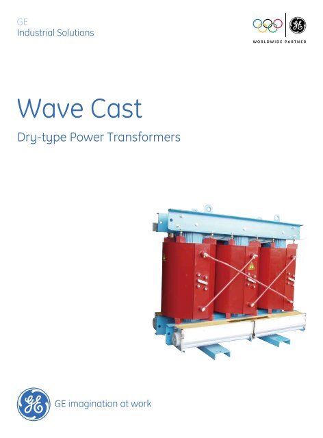
<strong>Wave</strong> <strong>Cast</strong><br />
Dry-type Power Transformers
<strong>GE</strong><br />
<strong>GE</strong> is a diversified organization covering a myriad of market segments, including infrastructure, finance and media.<br />
From energy, water, transportation and health to access to money and information, <strong>GE</strong> serves customers in more than<br />
100 countries and employs more than 300,000 people worldwide.<br />
The company traces its beginnings from Thomas A. Edison, who established the Edison Electric Light Company in 1878.<br />
In 1892, a merger of Edison General Electric Company and Thomson-Houston Electric Company created the General<br />
Electric Company. <strong>GE</strong> is the only company listed in the Dow Jones <strong>Industrial</strong> Index today that was also included in the<br />
original index in 1896.<br />
<strong>Industrial</strong> Solutions<br />
<strong>GE</strong> <strong>Industrial</strong> Solutions, a division of <strong>GE</strong> Energy Management, is a global leading provider in power distribution, offering a<br />
wide range of products which include medium and low voltage power distribution equipment and components, and<br />
motor & control systems that are safe, reliable and offer high performance. Its innovative solutions can improve energy<br />
efficiency and environmental impact in power plants, power grids, oil & gas, mining, data center, overseas EPC,<br />
industrial manufacturing, rail transportation, commercial buildings, residential houses, renewable energy and many<br />
other industries.<br />
<strong>GE</strong> is one of the worldwide partners of the Olympic Games. In 2008, <strong>GE</strong> assisted<br />
Beijing with this tremendous event, which was unprecedented in scale and<br />
first-class in its use of science and technology, offering a series of innovative<br />
solutions and products for around 400 Olympic infrastructure projects, covering<br />
fields in electricity distribution, lighting, security, water processing, benefiting<br />
some 37 Olympic venues and 168 commercial buildings. <strong>GE</strong> also brought its<br />
experiences to the 2010 Expo in Shanghai, Asia Games in Guangzhou,<br />
Vancouver Olympic Games and continued through to the London 2012 Olympic<br />
Games.<br />
2011 World’s Most Admired Companies<br />
2010 World's Most Innovative Companies<br />
2009 World’s Most Respected Companies<br />
2011 Best Global Brand<br />
2008 World’s Most Respected Companies 2007 World’s Best R&D Companies
Contents<br />
<strong>Wave</strong> <strong>Cast</strong> Transformers ……………………………… 01<br />
Vacuum cast windings ………………………………… 02<br />
Winding assembly ……………………………………… 03<br />
Cores …………………………………………………… 04<br />
Enclosures ……………………………………………… 04<br />
Accessories ……………………………………………… 05<br />
Technical specifications ………………………………… 06<br />
Tests …………………………………………………… 10<br />
Certificates ……………………………………………… 11<br />
Handling ………………………………………………… 12<br />
Foundation ……………………………………………… 13
<strong>Wave</strong> <strong>Cast</strong> Transformers<br />
Reliability, flexibility, efficiency and safety<br />
<strong>Wave</strong> <strong>Cast</strong> coil transformers from <strong>GE</strong> are characterized by proven technology, application<br />
flexibility, lower installation cost, operating efficiency and environmental acceptability.<br />
Advanced design of the winding assembly establishes superior performance to meet<br />
today’s exacting needs. Indoors or out, they are designed for use in the most demanding<br />
and diverse environments and in all applications requiring reliable electrical power.<br />
Typical applications of cast coil transformers include:<br />
• Steel mills<br />
• <strong>Industrial</strong> critical power solutions<br />
• Windmills<br />
• Offshore drilling platforms<br />
• Pulp & paper mills<br />
• Chemical plants<br />
• Cement & mining operations<br />
• Automotive industry<br />
• High rise building & water-side installations<br />
<strong>Cast</strong> coil transformers boast several advantages over alternative transformer technologies.<br />
• Mechanical strength. Because of the strong protection provided by the vacuum cast<br />
epoxy encapsulated coils, <strong>Wave</strong> <strong>Cast</strong> transformers are stronger than either liquid or<br />
ventilated dry-type transformers. Short circuit tests have proven this strength well beyond<br />
IEC and ANSI requirements. <strong>GE</strong> designs and manufactures its cast coils to be among the<br />
strongest in the industry. The strength of <strong>Wave</strong> <strong>Cast</strong> transformers makes them ideal for<br />
such applications as impact loading, mobile machinery and transit systems.<br />
• Impervious to adverse atmospheric conditions. Unlike ventilated dry-type transformers<br />
and in a manner similar to liquid filled transformers, <strong>GE</strong> <strong>Cast</strong> Coil transformers are optimal<br />
for application in harsh environments. The epoxy casting is extremely inert and renders<br />
the windings impervious to moisture, dirt and most corrosive elements.<br />
• Suitability for simple indoor installations. Unlike the case with liquid filled transformers,<br />
indoor installations do not require an automatic fire extinguishing system or fire vault, oil<br />
checking or replacing, or a liquid confinement area.<br />
• Extended ratings. <strong>GE</strong> cast coil transformers can be provided with the highest self-cooled<br />
and fan-cooled extended ratings of any transformers in their size class.<br />
• High efficiency and environmental safety. <strong>Wave</strong> <strong>Cast</strong> coil transformers have several<br />
distinct advantages over dry and liquid filled transformer. The main advantage of a cast<br />
coil transformer is that the polyester glass and epoxy resin provides excellent mechanical<br />
strength and eliminates conductor movement since both the primary and secondary<br />
windings are completely capsulated in the epoxy resin. As with other dry transformer,<br />
the electromagnetic force under short circuit conditions tends to push the secondary<br />
winding into the core, while driving the primary winding away from the core. In addition<br />
to using the strength of the conductor material and winding geometry, the cast coil<br />
design incorporates the concrete-like epoxy-conductor matrix. Wedging sticks are placed<br />
between the secondary windings and the core legs to center the coils on the core legs.<br />
The primary winding is completely embedded in a block of epoxy, which prevents any<br />
winding movement.<br />
The epoxy resin essentially makes the cast coil transformer impervious to harsh<br />
environments and has no potential adverse affects on the environment. Thus it can be<br />
used virtually in any application. Another advantage is that the cast coil transformer has<br />
a higher efficiency rating than liquid or dry transformer.<br />
1
Vacuum cast windings<br />
Tough epoxy provides the strength.<br />
<strong>Wave</strong> <strong>Cast</strong> vacuum cast windings are highly engineered<br />
components, requiring specific expertise in electrical,<br />
material, thermal and mechanical engineering. The process of<br />
measuring, mixing, heating and vacuum casting materials into<br />
the windings is equally critical.<br />
<strong>Cast</strong> coils are solid vacuum cast with epoxy resin compound.<br />
The epoxy is applied under vacuum to hermetically seal the<br />
windings in a highly durable epoxy. Quartz filler is included,<br />
which provides increased viscosity to the resin, better<br />
impregnation and increased capability to withstand short<br />
circuits. The epoxy mixture is carefully designed to provide<br />
maximum strength and environmental protection and yet<br />
minimize the temperature differential through the coil thickness.<br />
Process control ensures that the coils are void-free and<br />
prevents partial discharges within the resin material or cracking<br />
of the epoxy over a wide range of ambient and operating<br />
temperatures<br />
The principal advantage of solid vacuum cast construction is<br />
that the cast coils seal out harmful fumes, air and moisture,<br />
preventing them from entering the windings. The solid cast<br />
transformer achieves a maximum degree of resin impregnation<br />
during the casting process.<br />
Other advantages of vacuum cast construction include:<br />
• Dielectric strength - Windings are corona-free at twice the<br />
rated voltage.<br />
• Mechanical strength - Short circuit capability meets and<br />
exceeds the requirements of IEC60076-11:2004 and IEEE<br />
standard C57.12.91-2001.<br />
• Thermal strength - Withstands fluctuating operating<br />
temperatures ranging from -40℃ to 180℃ without damage<br />
to the epoxy insulation.<br />
• Insulation system - Tested to ANSI/NEMA and IEC standards,<br />
turn-turn and layer-layer electrical insulation components<br />
(polyimide film) are recognized at 180℃.<br />
2
Winding assembly<br />
High and low voltage windings are vacuum cast in metal molds as separate concentric cylinders.<br />
High voltage windings are wound using strip foil technology. Multiple layers of polyimide film (180℃ system) provide turn insulation.<br />
Individual coil sections are wound directly onto the HV winding form and then connected in series by welding. Molds are assembled<br />
around the completed high voltage coils and placed in a vacuum chamber. Coils are pre-heated under high vacuum to remove trapped<br />
moisture. A special mixture of epoxy resin and quartz powder flows into the mold through an opening in the molding assembly. After<br />
pouring, the molds are cured in a time-temperature process controlled oven. The result is a reliable, vacuum cast winding with an<br />
unusually high-strength essentially void free assembly capable of withstanding high electrical stress.<br />
Low voltage windings use sheet conductor construction. A fiberglass mesh provides support for the inside of the winding. Full-width<br />
sheet conductor and SCC layer insulation is wound onto the cylinder. Start and finish lead bars are TIG welded to the sheet conductor.<br />
Low voltage windings are also vacuum cast in a metal mold using the same technique as the high voltage windings.<br />
Why strip foil windings<br />
• High power frequency and impulse-voltage strength<br />
• Virtual absence of partial discharges<br />
• High short-circuit strength<br />
• Low noise levels<br />
• Low hotspot temperature rise differential<br />
3
Cores<br />
Construction ensures optimal performance.<br />
Transformer cores utilize mitered step-lap technology to optimize performance and<br />
minimize sound levels. Cores are constructed of non-aging, high permeability, grainoriented<br />
silicon steel laminations without punched holes offering high magnetic<br />
permeability.<br />
Core laminations are free of burrs and stacked without gaps, resulting in the lowest<br />
possible losses from magnetic hysteresis and eddy currents. The core clamping brackets<br />
are designed to provide an even distribution of clamping forces to the core yokes and<br />
legs and are rigidly braced to reduce sound levels and losses.<br />
Other core construction benefits include:<br />
• Magnetic flux densities, kept well below saturation point<br />
• Surfaces of the core, clamps and tie rods are all treated against corrosion<br />
Enclosures<br />
Withstands the harshest indoor and outdoor environments.<br />
Enclosures are suitable for lifting, jacking, rolling or skidding with provisions for lifting the<br />
transformer from its base. The standard indoor enclosures are IP20, IP30 and NEMA 1,<br />
Category C construction.<br />
While core and coil technologies have been enhanced to combat caustic and humid<br />
environments, <strong>Wave</strong> <strong>Cast</strong> transformers are further protected by properly designed<br />
enclosures. <strong>GE</strong> enclosures are custom fabricated using heavy gauge sheet steel. Optional<br />
aluminum and stainless steel enclosures are available.<br />
Additional protection against harsh outdoor or indoor environments is provided through<br />
electrostatically deposited dry powder paint baked onto a phosphate treated surface. The<br />
paint finish is neat, clean and highly resistant to corrosion.<br />
A variety of optional enclosures is available: drip proof roofs, supplemental filters, screens,<br />
hinged panels and special hardware. Other modifications can also be made to extend the<br />
enclosure, add bottom plates, add end sheets and/or include special cutouts for specific<br />
applications.<br />
4
Accessories<br />
Temperature monitor/fan controller<br />
The controller can display the operating temperature of windings, control<br />
fans and provide temperature alarm, ensuring effective monitoring and<br />
protection of the transformer.<br />
The PT100 sensors are inserted into each LV winding to send the temperature<br />
signal, which can be displayed on the panel.<br />
Main function:<br />
• Setting alarm temperature level<br />
• Record the maximum temperature in non-volatile memory,<br />
• Send fault signal and alarm<br />
• Send audible over-temperature alarm, alarm signal and trip signal<br />
• Start and stop fans automatically or manually (optional)<br />
• Provide communication interface (optional)<br />
Cross flow fan<br />
The low noise cross flow fan can reduce the winding temperature, enhance<br />
the overload ability, and prolong the service life of transformer.<br />
The rated power of transformer can be increased by 25-40% when forced<br />
air-cooling is used.<br />
Controller Panel<br />
Cross flow Fan<br />
Roller<br />
4 rollers can be equipped under a transformer or enclosure to facilitate<br />
moving in two directions.<br />
5
Technical specifications<br />
Standard products<br />
IEC<br />
ANSI / IEEE<br />
Phases 3<br />
Conductors<br />
Copper or Aluminum<br />
Frequency (Hz) 50 60<br />
Primary Voltages (kV) Up to 35<br />
Secondary Voltages (kV) Up to 10<br />
Power (kVA) 160 - 10,000<br />
Off-load tapping range ±2×2.5%, ±5% *<br />
Insulation class F (155℃) or H (180℃) 150℃or 180℃<br />
Ambient temperature (℃)<br />
Max<br />
≤40<br />
Min ≥-5 (indoor), ≥-25 (outdoor) ≥-30<br />
Altitude (m) ≤1,000<br />
Connection<br />
Dyn5, Dyn11, YNd11, Yyn0 and others<br />
Cooling AN, AN/AF, AF AA, AA/FA, AFA<br />
* Other taps are available on request.<br />
Accessories / options<br />
• Enclosures: IP20, IP21, IP23, NEMA 1, NEMA<br />
3R and others<br />
• Space heaters<br />
• Thermostat for space heaters<br />
• 120/240V fans for forced-air cooling ratings<br />
• Temperature monitor/fan controller<br />
• Rollers<br />
Special design or application<br />
• Larger power<br />
• Higher secondary Voltage<br />
• Special ambient<br />
• Special altitude<br />
• On-load tap changing<br />
• High overload capacity<br />
• Low loss<br />
• Special short-circuit impedance<br />
• Special usage<br />
Applicable standards<br />
• IEC 60076-11:2004<br />
Dry-type transformers<br />
• IEEE C57.12.01-2005<br />
General requirements for dry-type distribution<br />
and power transformers including those with<br />
solid-cast and/or resin-encapsulated windings.<br />
6
Technical specifications<br />
Phase number Frequency Service condition<br />
Tapping range of<br />
HV winding<br />
Connection symbol<br />
Insulation class<br />
Temperature rise<br />
limit<br />
3 50 Hz<br />
Normal condition according to<br />
IEC60076-11: 2004<br />
±2×2.5% or ±5%<br />
Dyn, Yyn,<br />
Yd, YNd<br />
F<br />
100K<br />
Copper windings, distribution transformers<br />
HV Um=12kV LV Um≤1.1kV<br />
Rated Power kVA 200 315 400 500 630 800 1000 1250 1600 2000 2500 3150<br />
No-load Loss W 700 1000 1080 1250 1300 1550 1800 2000 2600 3400 4000 5000<br />
Load Loss 75℃ W 2280 2990 3520 4100 5300 6500 7210 8570 10700 12800 15400 20000<br />
Load Loss 120℃ W 2600 3400 4000 4650 6000 7350 8100 9600 12000 14400 17000 22000<br />
Short-circuit Impedance % 4 4 4 4 6 6 6 6 6 6 6 6<br />
Noise LPA dB 46 46 46 48 48 50 50 50 52 54 56 58<br />
Length mm 1170 1230 1260 1310 1410 1470 1500 1580 1700 1890 2010 1970<br />
Width mm 750 750 750 750 750 920 920 920 920 920 1170 1270<br />
Height mm 930 1040 1110 1160 1170 1280 1400 1440 1570 1570 1620 1960<br />
Weight kg 1040 1330 1500 1750 2010 2310 2710 3190 3920 4930 5730 6400<br />
Distance Between Rollers mm 660 660 660 660 660 820 820 820 820 820 1070 1070<br />
HV Um=24kV LV Um≤1.1kV<br />
Rated Power kVA 315 400 500 630 800 1000 1250 1600 2000 2500 3150<br />
No-load Loss W 1100 1200 1400 1500 1800 2100 2400 2600 3500 4300 5000<br />
Load Loss 75℃ W 2990 4050 4920 6020 6500 7470 9440 10700 12800 15400 20000<br />
Load Loss 120℃ W 3400 4600 5600 6800 7350 8400 10600 12000 14400 17000 22000<br />
Short-circuit Impedance % 6 6 6 6 6 6 6 6 6 6 6<br />
Noise LPA dB 48 48 50 50 52 52 52 54 56 58 60<br />
Length mm 1380 1370 1400 1530 1590 1650 1710 1850 2010 2100 2130<br />
Width mm 750 750 750 750 920 920 920 920 1170 1170 1270<br />
Height mm 1220 1290 1360 1360 1400 1500 1650 1760 1800 1830 2060<br />
Weight kg 1520 1620 1850 2080 2550 3050 3570 4500 5450 6070 7050<br />
Distance Between Rollers mm 660 660 660 660 820 820 820 820 1070 1070 1070<br />
HV Um=40.5kV LV Um≤1.1kV<br />
Rated Power kVA 630 800 1000 1250 1600 2000 2500 3150<br />
No-load Loss W 1840 2100 2450 2800 3200 3900 4600 5500<br />
Load Loss 75℃ W 6020 7100 8000 11600 12900 13900 17500 21500<br />
Load Loss 120℃ W 6800 8000 9000 13000 14500 14600 20000 23500<br />
Short-circuit Impedance % 6 6 6 6 6 6 6 6<br />
Noise LPA dB 54 56 58 60 60 62 62 62<br />
Length mm 1670 1680 1770 1800 1890 1950 2100 2280<br />
Width mm 920 920 920 920 1270 1270 1270 1270<br />
Height mm 1560 1580 1620 1900 1960 2180 2180 2180<br />
Weight kg 2600 2800 3500 3900 4600 5700 6700 7700<br />
Distance Between Rollers mm 820 820 820 820 1070 1070 1070 1070<br />
Other powers and voltages are available on request.<br />
7
Technical specifications<br />
Aluminum windings, distribution transformers<br />
HV Um=12kV LV Um≤1.1kV<br />
Rated Power kVA 315 400 500 630 800 1000 1250 1600 2000 2500 3150<br />
No-load Loss W 900 1000 1200 1300 1600 1800 2150 2600 3300 4000 5000<br />
Load Loss 75℃ W 3100 3500 4200 5380 6600 7100 8400 10800 12800 14500 19500<br />
Load Loss 120℃ W 3500 4000 4800 6100 7500 8100 9600 11600 14000 16000 21000<br />
Short-circuit Impedance % 4 4 4 6 6 6 6 6 6 6 6<br />
Noise LPA dB 46 46 48 48 50 50 50 52 54 56 58<br />
Length mm 1310 1320 1350 1520 1560 1610 1680 1740 1860 2070 2130<br />
Width mm 750 750 750 750 920 920 920 920 920 1170 1170<br />
Height mm 1090 1200 1300 1310 1410 1550 1640 1800 1840 1890 2050<br />
Weight kg 1300 1500 1700 1880 2200 2580 3060 3760 4300 5500 6400<br />
Distance Between Rollers mm 660 660 660 660 820 820 820 820 820 1070 1070<br />
HV Um=24kV LV Um≤1.1kV<br />
Rated Power kVA 315 400 500 630 800 1000 1250 1600 2000 2500 3150<br />
No-load Loss W 1200 1300 1500 1600 1700 2000 2400 3000 3500 4000 5000<br />
Load Loss 75℃ W 3100 3500 4300 6350 7700 7400 9300 11200 12800 14500 19500<br />
Load Loss 120℃ W 3500 4000 4900 7300 8700 8400 10600 12500 14400 16000 21000<br />
Short-circuit Impedance % 6 6 6 6 6 6 6 6 6 6 6<br />
Noise LPA dB 48 48 50 50 52 52 52 54 56 58 60<br />
Length mm 1470 1470 1490 1590 1620 1780 1770 1890 1980 2130 2210<br />
Width mm 750 750 750 920 920 920 920 920 1170 1170 1170<br />
Height mm 1350 1390 1410 1420 1520 1650 1770 1930 1960 2040 2180<br />
Weight kg 1550 1650 1900 2000 2150 2650 3300 4060 4850 5800 6900<br />
Distance Between Rollers mm 660 660 660 820 820 820 820 820 1070 1070 1070<br />
Other powers and voltages are available on request.<br />
Copper windings, power transformers<br />
HV Um=40.5kV LV Um>1.1kV<br />
Rated Power kVA 1000 1250 1600 2000 2500 3150 4000 5000 6300 8000 10000 12500<br />
No-load Loss W 2700 3200 3600 4300 4500 5400 6500 8300 9000 11000 12800 14500<br />
Load Loss 75℃ W 8500 10600 11200 13500 16000 21000 25000 3000 34000 40000 46000 55000<br />
Load Loss 120℃ W 9600 12000 12800 15000 18000 24000 28000 34000 38000 47000 55000 62000<br />
Short-circuit Impedance % 6 6 6 7 7 8 8 8 8 9 9 9<br />
Noise LPA dB 58 60 60 61 61 62 62 63 63 65 65 67<br />
Length mm 1950 2010 2070 2150 2100 2430 2500 2760 2780 3000 3150 3300<br />
Width mm 920 920 920 1270 1270 1270 1270 1675 1675 1675 1675 1675<br />
Height mm 1700 1800 1880 1960 2180 2130 2260 2300 2370 2660 2750 2950<br />
Weight kg 3700 4500 5100 6150 6650 7850 9250 11500 13200 15300 18100 22500<br />
Distance Between Rollers mm 820 820 820 1070 1070 1070 1475<br />
Other powers and voltages are available on request. Aluminum windings are available as well.<br />
1475 (W)<br />
2040 (L)<br />
1475 (W)<br />
2040 (L)<br />
1475 (W)<br />
2040 (L)<br />
1475 (W)<br />
2040 (L)<br />
1475 (W)<br />
2040 (L)<br />
8
IP23 outdoor enclosure<br />
IP30 enclosure<br />
Technical specifications<br />
Enclosures<br />
Rated<br />
power<br />
(kVA)<br />
Nominal Outline Dimension<br />
Length (mm) Width (mm) Height (mm)<br />
1600 1800 2000 2200 2400 2600 2800 3000 3200 1200 1400 1600 1800 2000 1800 2000 2200 2400 2800<br />
315 1 2 2 12 12<br />
400 1 2 12 12<br />
500 1 2 12 1 2<br />
630 1 2 2 3 1 12 3 1 12 3<br />
800 1 1 2 3 12 3 1 1 23<br />
1000 1 1 2 2 3 3 12 3 1 123<br />
1250 1 2 2 3 3 12 3 1 12 3<br />
1600 1 1 2 3 3 3 12 3 1 123<br />
2000 1 1 2 3 3 1 1 23 3 1 12 3<br />
2500 1 1 2 3 3 3 1 23 3 1 12 3<br />
3150 1 2 2 3 3 1 23 3 1 123<br />
Notes: 1 – HV Um=12kV, 2 – HV. Um=24kV, 3 – HV Um=40.5kV;<br />
Outline dimensions of enclosure are related with not only rated power and primary voltage of transformer, but also conductor material<br />
used. Please contact us for your specific application.<br />
Available connecting method<br />
• Cable top in-coming or out-going<br />
• Cable bottom in-coming or out-going<br />
• Busbar top out-going<br />
• Busbar lower side out-going<br />
• Busbar upper side out-going<br />
Other connecting methods, Please contact us.<br />
Standard enclosure type<br />
• IP23, NEMA 3R for outdoor installation<br />
• IP20, IP21, IP30, NEMA 1 for indoor installation<br />
Height<br />
Width<br />
Length<br />
9
Tests<br />
Tests are performed in accordance with IEC60076-11:2004 or<br />
IEEE C57.12.91-2001.<br />
Routine tests<br />
Each cast coil transformer is submitted to a complete set of<br />
routine tests for ensuring transformer reliable.<br />
• Measurements of winding resistance<br />
• Measurement of voltage ratio and check of phase<br />
displacement<br />
• Measurement of insulation resistance<br />
• Measurement of short circuit impedance and load losses<br />
• Measurement of no-load losses and current<br />
• Separate-source AC voltage withstand voltage test<br />
• Induced AC withstand voltage test<br />
• Measurement of partial discharge<br />
Type tests<br />
Type test is performed in case of new design or important<br />
design modification in order to confirm that the quality of<br />
transformer is compliance to related standard. They can be<br />
carried out according to custom request.<br />
• Temperature-rise test<br />
• Lightning impulse test<br />
Special tests<br />
Can be performed upon request<br />
• Sound level test<br />
• Short-circuit test<br />
<strong>Wave</strong> <strong>Cast</strong> had pass the following tests:<br />
• Short-circuit test at KEMA Holand on one 2.5MVA<br />
transformer<br />
• All the routine, type and special tests at CTQC witnessed<br />
by KEMA on both one 1600kVA 11/0.4kV copper winding<br />
transformer and one 2000kVA 20/0.4kV aluminium winding<br />
transformer. (KEMA report)<br />
• All the routine, type and special tests at CTQC (China<br />
Transformer Quality Center) on one 2MVA distribution<br />
transformer<br />
• All the routine, type and special tests at CTQC on one<br />
10MVA power transformer<br />
• The C2 climatic class, E2 environmental class, F1 fire<br />
behaviour class tests at CTQC<br />
• Vibration test withstand the acceleration a g of the horizontal<br />
0.6g and vertical 0.3g at Tongji University<br />
Standard insulation level<br />
IEC<br />
Highest Voltage for<br />
equipment Um<br />
(r.m.s)<br />
(kV)<br />
ANSI/IEEE<br />
Rated short duration<br />
separate source AC<br />
withstand voltage<br />
(r.m.s)<br />
(kV)<br />
Rated lightning<br />
impulse withstand<br />
voltage (peak value)<br />
(kV)<br />
≤1.1 3 -<br />
3.6 10 40<br />
7.2 20 60<br />
12 28 75<br />
17.5 38 95<br />
24 50 125<br />
36 70 170<br />
Nominal Voltage<br />
(kV)<br />
Low-frequency voltage Basic lightning impulse<br />
insulation levels (r.m.s) insulation level (crest)<br />
(kV)<br />
(kV)<br />
1.2 4 10<br />
2.5 10 20<br />
5 12 30<br />
8.7 19 45<br />
15 31 60<br />
25 37 110<br />
34.5 50 150<br />
ANSI/IEEE standard sound leveL<br />
Rated power (kVA) Self cooled (db) Fan cooled (db)<br />
300 55 67<br />
500 60 67<br />
800 64 67<br />
1000 64 67<br />
1600 66 68<br />
2000 66 69<br />
2500 68 71<br />
3150 70 71<br />
5000 71 73<br />
10
Certificates<br />
ISO 9001:2000 Certification awarded<br />
by Bureau Veritas Certification (BVQI)<br />
Hongkong<br />
2.5MVA 12.47kV power transformer<br />
short-circuit test report at KEMA USA<br />
1 6 0 0 k V A 1 1 k V C o p p e r w i n d i n g<br />
transformer test report of KEMA<br />
2000kVA 20kV Aluminium winding<br />
transformer test report of KEMA<br />
10MVA 35kV power transformer test<br />
report at CTQC<br />
Vibration test report at Tongji University<br />
11
Handling<br />
Handling transformer<br />
1. 4 hoisting joint hinges are installed on the upper clamps<br />
(channel-section) of transformer.<br />
2. It is suggested to hoist the body integrally by 4 steel cables.<br />
3. The included angle between steel cables is not more than 60<br />
degree.<br />
Transporting by fork-lift truck<br />
1. The fork shall be symmetrically placed under the enclosure<br />
base to avoid declining and overturn.<br />
2. The fork end shall be over the enclosure center to avoid<br />
declining and overturn.<br />
3. The speed shall be limited to avoid tossing.<br />
≤60°<br />
Hoisting hanger<br />
Steel cable<br />
Joint hinge<br />
Transformer<br />
Enclosure<br />
Fork-lift truck<br />
Enclosure center & Forks center<br />
Enclosure center<br />
Handling transformer with enclosure<br />
1. The 4 lifting pads are fixed on the base of enclosure.<br />
2. It is suggested to hoist the enclosure by 4 steel cables and<br />
spreader bar (or similar tools) as below.<br />
3. The included angle between steel cables is not more than 60<br />
degree.<br />
4. The special handling way, please refer to the sketch map on<br />
the enclosure.<br />
Enclosure<br />
Enclosure<br />
Fork-lift truck<br />
Fork end (over the enclosure center)<br />
Storage<br />
Fork-lift truck<br />
≤60°<br />
1. Transformer in storage and non-running period shall be<br />
away from severe moisture.<br />
2. The relative humidity of the surrounding air shall be less than<br />
93%. No drops of water shall be present on the surface of the<br />
coils.<br />
3. The details refer to the <strong>Wave</strong> <strong>Cast</strong> Manual.<br />
Handling transformer with enclosure<br />
12
Foundation<br />
Enclosure<br />
A B C<br />
Enclosure<br />
Concrete<br />
Concrete<br />
Cable trench<br />
(If applicable)<br />
Concrete<br />
Channel steel<br />
(inserted in concrete foundation)<br />
4-ø22<br />
Fix holes<br />
Channel steel<br />
(inserted in concrete foundation)<br />
Fix holes<br />
100<br />
100<br />
Fix holes<br />
100<br />
Enclosure bottom<br />
Cable trench<br />
(If applicable)<br />
Fix holes<br />
Transformer support channel steel<br />
Fix holes<br />
100<br />
13
Greater China<br />
Shanghai<br />
4F, Building 2, CTP, No.1 Hua Tuo Rd. Zhang Jiang Hi-Tech<br />
Park, Shanghai, China 201203<br />
T : +86 21 3877 7888<br />
F : +86 21 3877 7600<br />
South East Asia<br />
Malaysia<br />
Level 6, 1 Sentral, Jalan Travers, Kuala Lumpur Sentral<br />
Kuala Lumpur, Malaysia 50470<br />
T : +603 2273 9788<br />
F : +603 2273 7988<br />
Thailand<br />
25th floor, CRC Tower, All Seasons Place, 87/2 Wireless<br />
Road, Lumpini, Pathumwan, Bangkok 10330<br />
T : +66 2 648 0240<br />
F : +66 2 648 0200<br />
India<br />
India<br />
Polt No. 42/1 & 45/14, Electronic City-Phase II<br />
Bangalore-560100<br />
T: (080) 41434000<br />
F: (080) 41434199<br />
Australia & New Zealand<br />
Australia<br />
125-127 Long Street, Smithfield, Sydney, NSW 2164<br />
T : +61 2 8788 6911<br />
F : +61 2 8788 7224<br />
North Asia<br />
Japan<br />
11F, Akasaka Park Bldg.,5-2-20, Akasaka, Minato-ku<br />
Tokyo 107-6111<br />
T : +81 3 3588 5288<br />
F : +81 3 3585 3010<br />
Europe & Middle East<br />
Spain<br />
P.I. Clot del Tufau, s/n, E-08295 Sant Vicenç de <strong>Cast</strong>ellet<br />
T: +34 900 993 625<br />
Belgium<br />
Nieuwevaart 51, B-9000 Gent<br />
T: +32 (0)9 265 21 11<br />
Finland<br />
Kuortaneenkatu 2, FI-00510 Helsinki<br />
T: +358 (0)10 394 3760<br />
France<br />
Paris Nord 2, 13, rue de la Perdrix<br />
F-95958 Roissy CDG Cédex<br />
T: +33 (0)800 912 816<br />
Poland<br />
Ul. Odrowaza 15, 03-310 Warszawa<br />
T: +48 22 519 76 00<br />
and<br />
Ul. Leszczyńska 6, Bielsko-Biała 43-300<br />
T: +48 33 828 62 33<br />
Latin America<br />
Latin America<br />
790 N.W. 107th Avenue, Suite 200, Miami, Fl 33172 USA<br />
T: +1 305 551 5155<br />
Chile<br />
Vespucio Norte, Avenida Presidente Eduardo Frei<br />
Montalva 6001, Edificio N° 66<br />
Comuna: Conchalí, Sector el Cortijo, Santiago<br />
T: (56 2) 928-4700<br />
North America<br />
USA<br />
41 Woodford Avenue, Plainville CT, USA 06062<br />
and<br />
12305 Kurland Drive, Houston, TX USA 77034<br />
T: +1 800-431-7867<br />
Taiwan<br />
6F, No. 8, Min Sheng E. Rd., Sec. 3, Taipei 10480<br />
T : +886 2 2183 7000<br />
F : +886 2 2516 6829<br />
Philippines<br />
8F Net Cube Building, 30th Street, Corner 3rd Avenue,<br />
Crescent West Park, Global City Taguig 1634<br />
T : +63 2 877 7000<br />
F : +63 2 846 0629<br />
Vietnam<br />
Saigon Centre, Unit 1, Floor 7, Le Loi Boulevard, District 1<br />
HoChiMinh City<br />
T : +84 8 3914 6700<br />
F : +84 8 3827 8229<br />
New Zealand<br />
Level 1, 8 Tangihua Street, Auckland, North Island<br />
T : +64 9 353 6706<br />
F : +64 9 353 6707<br />
Korea<br />
3rd Floor, <strong>GE</strong> Tower, 71-3, Cheongdam-dong, Gangnam-gu<br />
Seoul, Korea 135-100<br />
T : +82 2 6201 4501<br />
F : +82 2 6201 4344<br />
Italy<br />
Centro Direzionale Colleoni, Via Paracelso 16<br />
Palazzo Andromeda B1, I-20041 Agrate Brianza (MB)<br />
T: +39 2 61 773 1<br />
Netherlands<br />
Parallelweg 10, Nl-7482 CA Haaksbergen<br />
T: +31 (0)53 573 03 03<br />
Germany<br />
Robert-Bosch Str. 2a, 50354 Hürth-Efferen<br />
T: +49 (0) 2233/ 9719-0<br />
Portugal<br />
Rua Camilo <strong>Cast</strong>elo Branco, 805, Apartado 2770<br />
4401-601 Vila Nova de Gaia<br />
T: +351 22 374 60 00<br />
Hungary<br />
Vaci ut 81-83. H-1139 Budapest<br />
T: +36 1 447 6050<br />
Brazil<br />
Av. María Coelho Aguiar, 215, Bloco C - 6.Andar<br />
Jd.São Luiz, 05804-900, São Paulo<br />
T: +55 11 36141900<br />
Mexico<br />
Av. Churubusco 3900 Nte, Col. <strong>Industrial</strong> Benito Juárez<br />
Monterrey, N.L. 64517<br />
T: (01-800) 800-1968<br />
Indonesia<br />
BRI II Tower, 27th floor, Jl. Jend. Sudirman No. 44-46<br />
Jakarta 10210<br />
T: +62 21 573 0430<br />
F: +62 21 574 7089<br />
Singapore<br />
240 Tanjong Pagar Road, #06-00 <strong>GE</strong> Tower<br />
Singapore 088540<br />
T : +65 6326 3718<br />
F : +65 6326 3015<br />
Russia<br />
27/8, Electrozavodskaya street, Moscow, 107023<br />
T: +7 495 937 11 11<br />
South Africa<br />
Unit 4, 130 Gazelle Avenue, Corporate Park Midrand 1685<br />
P.O. Box 76672 Wendywood 2144<br />
T: +27 11 238 3000<br />
United Arab Emirates<br />
1101, City Tower 2, Sheikh Zayed Road,<br />
P.O. Box 11549, Dubai<br />
T: +971 43131202<br />
United Kingdom<br />
Houghton Centre, Salthouse Road, Blackmills,<br />
Northampton<br />
NN4 7EX<br />
T: +44 (0)800 587 1239
<strong>GE</strong><br />
<strong>Industrial</strong> Solutions<br />
You may be interested in other MV Seco-family products<br />
For more information, please visit www.geindustrial.com<br />
For more information, please visit<br />
www.geindustrial.com<br />
Printing Code: IN201301B14EN<br />
© Copyright <strong>GE</strong> <strong>Industrial</strong> Solutions 2013