NX-587E VIRTUAL KEYPAD - Interlogix
NX-587E VIRTUAL KEYPAD - Interlogix
NX-587E VIRTUAL KEYPAD - Interlogix

Create successful ePaper yourself
Turn your PDF publications into a flip-book with our unique Google optimized e-Paper software.
<strong>NX</strong>-<strong>587E</strong> <strong>VIRTUAL</strong> <strong>KEYPAD</strong><br />
GENERAL DESCRIPTION<br />
This device will fully support the emulation of a bilingual (English and American Spanish) <strong>NX</strong>-148E or <strong>NX</strong>-1192E LCD keypad over a serial link to a<br />
host computer or automation with the exception functions unique to the LCD and sounder.<br />
PROGRAMMING<br />
Please refer to the <strong>NX</strong>-148E keypad instruction manuals for all normal and programming operations including Master and Temporary Partition<br />
modes. The functions not supported are 0 (Set Tone Pitch), 91 (Set Backlight Level and LCD Contrast) and 94 (Set Keypad Number and<br />
Partition). This unit uses a fixed address of 248 and normally operates in Partition 1.<br />
WIRING<br />
The serial port is configured to communicate at 9600 baud, 8 data bits, 1 stop bit and no parity. There is no hardware or software flow control;<br />
therefore the handshake lines should be ignored.<br />
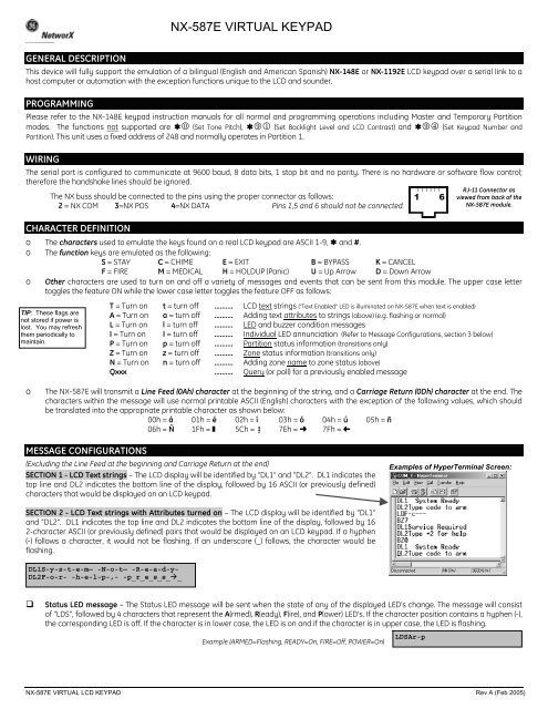
The <strong>NX</strong> buss should be connected to the pins using the proper connector as follows:<br />
2 = <strong>NX</strong> COM 3=<strong>NX</strong> POS 4=<strong>NX</strong> DATA Pins 1,5 and 6 should not be connected.<br />
1 6<br />
RJ-11 Connector as<br />
viewed from back of the<br />
<strong>NX</strong>-<strong>587E</strong> module.<br />
CHARACTER DEFINITION<br />
o The characters used to emulate the keys found on a real LCD keypad are ASCII 1-9, and #.<br />
o The function keys are emulated as the following:<br />
S = STAY C = CHIME E = EXIT B = BYPASS K = CANCEL<br />
F = FIRE M = MEDICAL H = HOLDUP (Panic) U = Up Arrow D = Down Arrow<br />
o Other characters are used to turn on and off a variety of messages and events that can be sent from this module. The upper case letter<br />
toggles the feature ON while the lower case letter toggles the feature OFF as follows:<br />
TIP: These flags are<br />
not stored if power is<br />
lost. You may refresh<br />
them periodically to<br />
maintain.<br />
T = Turn on t = turn off ………. LCD text strings (“Text Enabled” LED is illuminated on <strong>NX</strong>-<strong>587E</strong> when text is enabled)<br />
A = Turn on a = turn off ………. Adding text attributes to strings (above) (e.g. flashing or normal)<br />
L = Turn on l = turn off ………. LED and buzzer condition messages<br />
I = Turn on I = turn off ………. Individual LED annunciation (Refer to Message Configurations, section 3 below)<br />
P = Turn on p = turn off ………. Partition status information (transitions only)<br />
Z = Turn on z = turn off ………. Zone status information (transitions only)<br />
N = Turn on n = turn off ………. Adding zone name to zone status (above)<br />
Qxxx ………. Query (or poll) for a previously enabled message<br />
o<br />
The <strong>NX</strong>-<strong>587E</strong> will transmit a Line Feed (0Ah) character at the beginning of the string, and a Carriage Return (0Dh) character at the end. The<br />
characters within the message will use normal printable ASCII (English) characters with the exception of the following values, which should<br />
be translated into the appropriate printable character as shown below:<br />
00h = á 01h = é 02h = í 03h = ó 04h = ú 05h = ñ<br />
06h = Ñ 1Fh = œ 5Ch = 0 7Eh = þ 7Fh = ³<br />
MESSAGE CONFIGURATIONS<br />
(Excluding the Line Feed at the beginning and Carriage Return at the end)<br />
SECTION 1 - LCD Text strings – The LCD display will be identified by “DL1” and “DL2”. DL1 indicates the<br />
top line and DL2 indicates the bottom line of the display, followed by 16 ASCII (or previously defined)<br />
characters that would be displayed on an LCD keypad.<br />
Examples of HyperTerminal Screen:<br />
SECTION 2 - LCD Text strings with Attributes turned on – The LCD display will be identified by “DL1”<br />
and “DL2”. DL1 indicates the top line and DL2 indicates the bottom line of the display, followed by 16<br />
2-character ASCII (or previously defined) pairs that would be displayed on an LCD keypad. If a hyphen<br />
(-) follows a character, it would not be flashing. If an underscore (_) follows, the character would be<br />
flashing.<br />
DL1S-y-s-t-e-m— -N-o-t— -R-e-a-d-y-<br />
DL2F-o-r- -h-e-l-p-,- -p_r_e_s_s__<br />
<br />
Status LED message – The Status LED message will be sent when the state of any of the displayed LED’s change. The message will consist<br />
of “LDS”, followed by 4 characters that represent the A(rmed), R(eady), F(ire), and P(ower) LED’s. If the character position contains a hyphen (-),<br />
the corresponding LED is off. If the character is in lower case, the LED is on and if the character is in upper case, the LED is flashing.<br />
Example (ARMED=Flashing, READY=On, FIRE=Off, POWER=On)<br />
LDSAr-p<br />
<strong>NX</strong>-<strong>587E</strong> <strong>VIRTUAL</strong> LCD <strong>KEYPAD</strong> Rev A (Feb 2005)
Function LED message – The Function LED message will be sent when the state of any of the displayed LED’s change. The message will<br />
consist of “LDF”, followed by 5 characters that represent the S(tay), C(hime), E(xit), B(ypass), and C(ancel) LED’s. If the character position<br />
contains a hyphen (-), the corresponding LED is off. If the character is in lower case, the LED is on and if the character is in upper case, the LED<br />
is flashing.<br />
Example (STAY=On, CHIME=on, EXIT=Flashing, BYPASS=On, CANCEL=Off)<br />
SECTION 3 - Individual LED strings – Each individual LED will be reflected on the LCD display as “L” followed by<br />
one of 9 characters: A(rmed), R(eady), F(ire), P(ower), S(tay), C(hime), E(xit), B(ypass), or K(Cancel). Refer to<br />
“Character Definition” instructions above. The final number of each line represents the flash condition: 0 = Off,<br />
1 = On, 2 = Flashing. The buzzer will be reflected on the LCD display as “BZ” followed by the condition.<br />
LDFscEb-<br />
<br />
Buzzer message – The Buzzer message will be sent when the state of keypad sounder changes. The<br />
message will consist of “BZ”, followed by 1 number digit that indicates which type of sound in being<br />
produced.<br />
0 = No Sound 4 = Exit Beep (fast rate)<br />
1 = Steady Tone 5-6 are not defined<br />
2 = Alarm Beep (continuous) 7 = Chime Tone (ding-dong)<br />
3 = Exit Beep (slow rate) 8 = Error Beep (3 short beeps)<br />
Example (Producing a chime sound): BZ7<br />
Partition Status message – The Partition Status message will be sent when any of the represented conditions of a given partition change.<br />
The message will consist of “PA”, followed by the number or the partition the message represents. Then there will be 8 characters that<br />
represent the R(eady), A(rmed), S(tay), C(hime Mode), E(ntry Delay), E(xit Period (any)), P(revious Alarm) and S(iren On) conditions. If the<br />
character is in upper case, the condition is TRUE; if the character is in lower case, the condition is NOT TRUE. (Note: Each character represents<br />
a unique status condition, so review the “E”s carefully as they are positioned in sequence.)<br />
PA1RasCeEps<br />
Example (Partition 1 is Ready, Armed, in Chime Mode, and in Exit Delay):<br />
Zone Status message – The Zone Status message will be sent when any of the represented conditions of a given zone change. The message<br />
will consist of “ZN”, followed by a 3-digit number of the zone the message represents. Then there will be 9 characters that represent the<br />
F(ault), T(amper), T(rouble), B(ypass), A(larm Memory), I(nhibit), L(ow Battery), L(ost) and B(ypass Memory) conditions. If the character is in upper<br />
case, the condition is TRUE; if the character is in lower case, the condition is NOT TRUE. (Note: Each character represents a unique status<br />
condition, so review the “T”s and “L”s carefully as they are positioned in sequence.)<br />
Example (Zone 17 is Faulted and Bypassed)<br />
Zone Status message with zone name enabled – The Zone Status message will be sent when any of the represented conditions of a given<br />
zone change. The message will consist of “ZN”, followed by a 3-digit number of the zone the message represents. The 16 character zone<br />
name will follow, then there will be 9 characters that represent the F(ault), T(amper), T(rouble), B(ypass), A(larm Memory), I(nhibit), L(ow<br />
Battery), L(ost) and B(ypass Memory) conditions. If the character is in upper case, the condition is TRUE; if the character is in lower case, the<br />
condition is NOT TRUE. (Note: Each character represents a unique status condition, so review the “T”s and “L”s carefully as they are positioned<br />
in sequence.)<br />
Example (Zone 3 is Tampered): ZN003LIVING ROOM PIR fTtbaillb<br />
Query – The status of LEDs, buzzer, zones, and partitions can be obtained by entering a “Q” command. This is especially helpful when a<br />
system is initially powered up and the status is unknown.<br />
Q000 Provides current display text Q193 – Q200 Provides info for Partitions 1 to 8<br />
Q001 – Q192 Provides info for Zones 001 to 192 Q201 Provides info for all LEDs and buzzers<br />
NETWORX COMPATIBLE CONTROL PANELS: <strong>NX</strong>-4, <strong>NX</strong>-4V2, <strong>NX</strong>-6, <strong>NX</strong>-6V2, <strong>NX</strong>-8, <strong>NX</strong>-8V2, <strong>NX</strong>-8E<br />
** THIS <strong>NX</strong>-<strong>587E</strong> PRODUCT IS NOT UL APPROVED **<br />
ZN017FttBaillb<br />
(Can be cut out and used near computer monitor for quick reference.)<br />
<strong>NX</strong>-<strong>587E</strong> <strong>VIRTUAL</strong> LCD <strong>KEYPAD</strong> QUICK REFERENCE<br />
KEYSTROKES LEDS LEDS (cont’d) OTHER FEATURES PARTITION STATUS ZONE STATUS<br />
1 – 9 (numeric) LDS= LED Status Lxz=Individual LED T = Text on t = Text off R = Ready F = Fault<br />
S = Stay A = Armed x=status/function z=condition A = Attributes on a = Attributes off A = Armed T = Tamper<br />
C = Chime R = Ready A = Armed 0=Off , 1=On L = LED on l = LED off C = Chime T = Trouble<br />
E = Exit F = Fire R = Ready 2=Flashing I = Individual LED on i = Individual LED off E = Entry delay B = Bypass<br />
B = Bypass P = Power F = Fire P = Partition status on p = Partition status off E = Exit period A = Alarm Memory<br />
K = Cancel LDF= LED Function P = Power Z = Zone status on z = Zone status off P = Previous alarm I = Inhibit<br />
F = Fire S = Stay S = Stay N = Name on n = name off S = Siren on L = Low Battery<br />
M = Medical C = Chime C = Chime Qxxx = Query for previously enabled message L = Lost<br />
H = Hold-up E = Exit E = Exit BZ = Buzzer B = Bypass memory<br />
U = Up arrow B = Bypass B = Bypass<br />
D = Down arrow C = Cancel K = Cancel<br />
Upper case = LED flashing<br />
Lower case = LED on<br />
DL1 = Display Line 1<br />
DL2 = Display Line 2<br />
0 = No Sound<br />
1 = Steady Tone<br />
2 = Alarm Beep (continuous)<br />
TEXT DISPLAY<br />
Hyphen ( - ) = character not flashing<br />
Underscore ( _ ) = character flashing<br />
3 = Exit Beep (slow rate)<br />
4 = Exit Beep (fast rate)<br />
5-6 are not defined<br />
7 = Chime Tone (ding-dong)<br />
8 = Error Beep (3 short<br />
beeps)<br />
<strong>NX</strong>-<strong>587E</strong> <strong>VIRTUAL</strong> LCD <strong>KEYPAD</strong> Rev A (Feb 2005)