ROTANTA 46 RSC ROBOTIC - HettichLab
ROTANTA 46 RSC ROBOTIC - HettichLab
ROTANTA 46 RSC ROBOTIC - HettichLab

You also want an ePaper? Increase the reach of your titles
YUMPU automatically turns print PDFs into web optimized ePapers that Google loves.
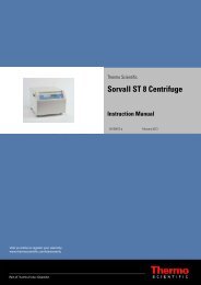
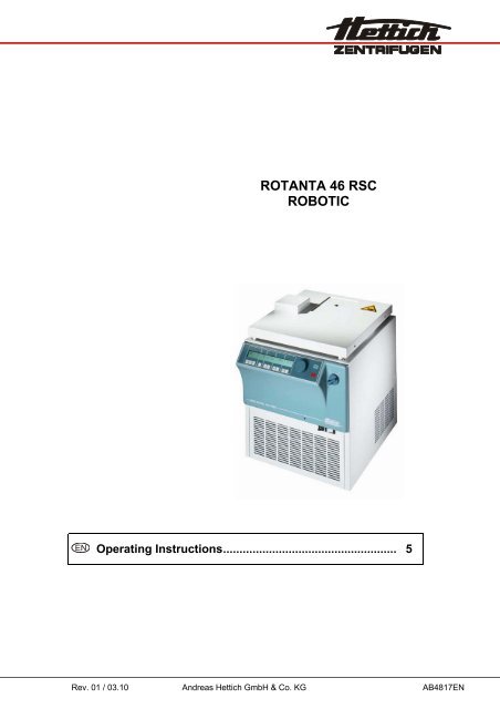
<strong>ROTANTA</strong> <strong>46</strong> <strong>RSC</strong><br />
<strong>ROBOTIC</strong><br />
EN Operating Instructions..................................................... 5<br />
Rev. 01 / 03.10 Andreas Hettich GmbH & Co. KG AB4817EN
A<br />
Fig. 1<br />
STOP 22 200<br />
4000 120:30<br />
PC LOCK1<br />
Fig. 2<br />
2/60
EG-Konformitätserklärung<br />
EC Conformity Declaration<br />
Déclaration de conformité CE<br />
Dichiarazione di conformità alle norme CEE<br />
Andreas Hettich GmbH & Co. KG • Föhrenstraße 12 • D-78532 Tuttlingen • Germany<br />
Das bezeichnete Gerät, inklusive Zubehör entspricht den aufgeführten EG-Richtlinien und Normen.<br />
The denoted device, including accessories corresponds to the listed EC guidelines and standards.<br />
L'appareil désigné, y compris les accessoires, correspond aux directives CE et aux normes énumérées.<br />
L'apparecchio designato, compresi gli accessori, è conforme alle direttive CE e alle norme citate.<br />
Geräteart, Type of device, Type d'appareil, Tipo di apparecchio:<br />
Laborzentrifuge mit Zubehör, Laboratory centrifuge with accessories, Centrifugeuse de<br />
laboratoire avec des accessoires, Centrifuga da laboratorio con accessori<br />
Typenbezeichnung, Type designation, Désignation de modèle, Contrassegno tipo:<br />
<strong>ROTANTA</strong> <strong>46</strong> <strong>RSC</strong> <strong>ROBOTIC</strong><br />
EG-Richtlinien/Normen, EC guidelines/standards, Directives CE/Normes, Direttive/Norme CEE:<br />
2006/95/EG, EN 61010-1:2001, EN 61010-2-020:2006<br />
2004/108/EG, EN 61326-1:2006<br />
2006/42/EG, EN ISO 12100-1:2004, EN ISO 12100-2:2004<br />
98/79/EG<br />
Tuttlingen, 28.09.2009<br />
H. Eberle<br />
Geschäftsführer, Manager,<br />
Directeur, Gerente<br />
3/60
Andreas Hettich GmbH & Co. KG<br />
Föhrenstraße 12, D-78532 Tuttlingen / Germany<br />
Phone +49 (0)7<strong>46</strong>1 / 705-0<br />
Fax +49 (0)7<strong>46</strong>1 / 705-125<br />
info@hettichlab.com, service@hettichlab.com<br />
www.hettichlab.com<br />
© 2007 by Andreas Hettich GmbH & Co. KG<br />
All rights reserved. No part of this publication may be reproduced without the prior written permission of the copyright<br />
owner.<br />
Modifications reserved!<br />
AB4817EN / Rev. 01 / 03.10<br />
4/60
EN<br />
Contents<br />
1 Use according to specification ................................................................................................................................8<br />
2 Residual risks .........................................................................................................................................................8<br />
3 Technical specifications..........................................................................................................................................8<br />
4 Notes on safety.....................................................................................................................................................10<br />
5 Symbol meanings .................................................................................................................................................11<br />
6 Delivery checklist ..................................................................................................................................................12<br />
7 Unpacking the centrifuge ......................................................................................................................................13<br />
8 Initial operation .....................................................................................................................................................13<br />
9 Opening and closing the lid...................................................................................................................................13<br />
9.1 Opening the lid ..............................................................................................................................................13<br />
9.2 Closing the lid ................................................................................................................................................13<br />
10 Installation and removal of the rotor ..................................................................................................................14<br />
11 Loading the rotor ...............................................................................................................................................14<br />
12 Control and display devices...............................................................................................................................14<br />
12.1 Status symbols...........................................................................................................................................14<br />
12.2 Control knob...............................................................................................................................................15<br />
12.3 Keys and set-up options.............................................................................................................................15<br />
13 Entering centrifugation parameters ...................................................................................................................16<br />
13.1 Running time..............................................................................................................................................16<br />
13.1.1 Time selection.....................................................................................................................................16<br />
13.1.2 Continuous running.............................................................................................................................16<br />
13.2 Speed (RPM) .............................................................................................................................................16<br />
13.3 Relative centrifugal force (RCF/RZB).........................................................................................................16<br />
13.4 Run-up and run-down parameters .............................................................................................................16<br />
13.4.1 Run-up step ........................................................................................................................................16<br />
13.4.2 Run-up time ........................................................................................................................................16<br />
13.4.3 Braking step........................................................................................................................................16<br />
13.4.4 Run-down time....................................................................................................................................16<br />
13.4.5 Brake de-energisation speed ..............................................................................................................17<br />
13.5 Radius/Temperature ..................................................................................................................................17<br />
13.5.1 Radius.................................................................................................................................................17<br />
13.5.2 Temperature (for centrifuges with cooling only) ..................................................................................17<br />
13.6 Automatic buffer.........................................................................................................................................17<br />
14 Programming.....................................................................................................................................................17<br />
14.1 Entering / modifying programs ...................................................................................................................17<br />
14.2 Calling up programs...................................................................................................................................17<br />
15 Centrifugation....................................................................................................................................................17<br />
15.1 Centrifugation with time selection ..............................................................................................................18<br />
15.2 Continuous running....................................................................................................................................18<br />
16 Changing settings during the centrifugation run. ...............................................................................................18<br />
17 Integral RCF (∫RCF) ..........................................................................................................................................18<br />
18 Displaying the maximum speed of the rotor ......................................................................................................18<br />
5/60
EN<br />
19 Displaying the maximum RCF of the rotor.........................................................................................................18<br />
20 Emergency stop ................................................................................................................................................18<br />
21 Audible signal....................................................................................................................................................19<br />
22 Interrogating the operating hours ......................................................................................................................19<br />
23 Setting the date and time ..................................................................................................................................19<br />
24 Centrifugation data displayed after switching on. ..............................................................................................19<br />
25 Immediate display of the centrifugation data after switching on ........................................................................19<br />
26 Key-operated switch (for centrifuges with key-operated switch only). ...............................................................20<br />
27 Program linking (for centrifuges with program linking only). ..............................................................................20<br />
27.1 Linking programs .......................................................................................................................................20<br />
27.2 Changing program links .............................................................................................................................20<br />
27.3 Centrifugation run with program linking......................................................................................................20<br />
27.4 Deleting program linking ............................................................................................................................21<br />
28 Cooling (only in centrifuges with cooling) ..........................................................................................................21<br />
28.1 Standby-cooling .........................................................................................................................................21<br />
28.2 Pre-cooling the rotor ..................................................................................................................................21<br />
29 Heating (only on centrifuges with heating/cooling option) .................................................................................21<br />
30 Relative centrifugal force (RCF) ........................................................................................................................21<br />
31 Centrifugation of materials or mixtures of materials with a density higher than 1.2 kg/dm 3 ...............................22<br />
32 Rotor Identification ............................................................................................................................................22<br />
33 Emergency release ...........................................................................................................................................22<br />
34 Maintenance and servicing................................................................................................................................22<br />
34.1 Centrifuge (housing, lid and centrifuging chamber)....................................................................................23<br />
34.1.1 Surface cleaning and care ..................................................................................................................23<br />
34.1.2 Surface disinfection ............................................................................................................................23<br />
34.1.3 Removal of radioactive contaminants .................................................................................................23<br />
34.2 Rotors and Attachments ............................................................................................................................23<br />
34.2.1 Cleaning and care...............................................................................................................................23<br />
34.2.2 Disinfection .........................................................................................................................................24<br />
34.2.3 Removal of radioactive contaminants .................................................................................................24<br />
34.2.4 Trunnions............................................................................................................................................24<br />
34.2.5 Rotors and accessories with limited service lives ...............................................................................24<br />
34.3 Autoclaving ................................................................................................................................................24<br />
34.4 Centrifuge containers.................................................................................................................................25<br />
35 Faults ................................................................................................................................................................25<br />
36 Description for Robotic......................................................................................................................................26<br />
36.1 Operational modes.....................................................................................................................................26<br />
36.1.1 Normal robotic operation.....................................................................................................................26<br />
36.1.2 Adjusting and initializing operation respectively handling of the centrifuge without serial interface ....26<br />
36.2 Introduction for serial operation..................................................................................................................27<br />
36.2.1 HETTICH Centrifuge-BUS ..................................................................................................................27<br />
36.2.2 Used telegrams:..................................................................................................................................27<br />
36.3 Time behaviour for serial operation............................................................................................................28<br />
36.3.1 Time for one ENQUIRY-Telegram ......................................................................................................28<br />
36.3.2 Time for one SELECT-Telegram ........................................................................................................28<br />
6/60
EN<br />
36.4 Address of the Centrifuge ..........................................................................................................................30<br />
36.5 Principle for serial communication .............................................................................................................30<br />
36.6 Summary of centrifuge parameter..............................................................................................................31<br />
36.7 General format of parameter content .........................................................................................................32<br />
36.8 Introduction in the most important parameters for serial drive of the centrifuge.........................................33<br />
36.8.1 Parameter for positioning (00640):......................................................................................................33<br />
36.8.2 Parameter for centrifuge state (00634) ...............................................................................................34<br />
36.8.3 Control commands for centrifugation ..................................................................................................35<br />
36.8.4 Special functions: ACK, NAK and SIOF..............................................................................................35<br />
36.9 Description of PARAMETER......................................................................................................................36<br />
36.10 Additional informations...............................................................................................................................49<br />
36.10.1 Serial communication and displaying..................................................................................................49<br />
36.10.2 Content of serial parameter ................................................................................................................49<br />
36.10.3 Software-Lock.....................................................................................................................................50<br />
36.10.4 Checking values for validity ................................................................................................................50<br />
36.10.5 Limitations...........................................................................................................................................50<br />
36.10.6 Query of actual values ........................................................................................................................50<br />
36.10.7 Set bit of the modification....................................................................................................................50<br />
36.11 Example for enquiry and command............................................................................................................50<br />
36.11.1 Open the hatch ...................................................................................................................................51<br />
36.11.2 Go to position 1 and check the reached position ................................................................................51<br />
36.11.3 Go to position 2 and check the reached position ................................................................................52<br />
36.11.4 Go to position 3 and check the reached position ................................................................................52<br />
36.11.5 Go to position 4 and check the reached position. ...............................................................................52<br />
36.11.6 Close the hatch...................................................................................................................................53<br />
36.11.7 Start the centrifuge!.............................................................................................................................53<br />
36.11.8 STOP per PC = Emergency stop ........................................................................................................53<br />
36.11.9 Cancel Software-lock LOCK 4 or LOCK 5 ..........................................................................................53<br />
36.11.10 Change the Nominal Values in stand still or during the run.............................................................54<br />
36.11.11 Recall (RCL) a program stored in the control panel, ready to start..................................................54<br />
36.11.12 Change the values of a stored program and read out via serial interface .......................................55<br />
36.11.13 The PC writes an new program which will be stored in the control panel........................................56<br />
36.11.14 Enquiry for program ID ....................................................................................................................57<br />
36.11.15 Centrifuging report after standstill....................................................................................................57<br />
37 Acceptance of the centrifuges for repair............................................................................................................58<br />
38 Disposal ............................................................................................................................................................58<br />
39 Anhang / Appendix ............................................................................................................................................59<br />
39.1 Rotoren und Zubehör / Rotors and accessories.........................................................................................59<br />
7/60
EN<br />
1 Use according to specification<br />
The machine presented here is a medical product (laboratory centrifuge) according to the IVD guideline 98/79/EG.<br />
The centrifuge is used to separate substances or substance mixtures with a density of max. 1.2 kg/dm³. This also<br />
includes substances and substance mixtures of human origin. The centrifuge is only intended to be used for this<br />
purpose. A different use or application over and above this is deemed not in accordance with the specifications. The<br />
company Andreas Hettich GmbH & Co. KG undertakes no liability for damages resulting therefrom.<br />
Belonging to the application according to specification is also the observance of all references contained in the<br />
Instruction Manual and compliance with the inspection and maintenance works.<br />
2 Residual risks<br />
The machine is constructed according to the state of the art and the recognized technical safety regulations.<br />
Improper use and handling can result in dangers to life and limb of the user or third parties and impairments to the<br />
machine or to other material assets. The machine is only to be used for the specified applications and only in an<br />
impeccable technical safety condition.<br />
Disturbances that can interfere with the safety are to be immediately rectified.<br />
3 Technical specifications<br />
Manufacturer<br />
Andreas Hettich GmbH & Co. KG<br />
D-78532 Tuttlingen<br />
Model<br />
<strong>ROTANTA</strong> <strong>46</strong> <strong>RSC</strong> <strong>ROBOTIC</strong><br />
4817,<br />
4817-RS232,<br />
4817-10,<br />
4817-08,<br />
4817-08-RS232,<br />
4817-18,<br />
4817-05,<br />
4817-05-RS232,<br />
4817-15,<br />
4817-01,<br />
4817-01-RS232,<br />
4817-11,<br />
4817-04,<br />
4817-04-RS232,<br />
4817-14,<br />
4817-10-RS232, 4817-18-RS232, 4817-15-RS232, 4817-11-RS232, 4817-14-RS232,<br />
Type<br />
4817-30-A, 4817-38-A, 4817-35-A, 4817-31-A, 4817-34-A,<br />
4817-30-D,<br />
4817-40,<br />
4817-50<br />
4817-38-D,<br />
4817-48,<br />
4817-58<br />
4817-35-D,<br />
4817-45,<br />
4817-55<br />
4817-31-D,<br />
4817-41,<br />
4817-51,<br />
4817-34-D,<br />
4817-44,<br />
4817-54<br />
Mains voltage (± 10%) 230-240 V 1∼ 200-220 V 1∼ 127 V 1∼ 110-120 V 1∼ 100 V 1∼<br />
Mains frequency<br />
50-60 Hz<br />
Connected load<br />
max. 2000 VA<br />
Cooling medium<br />
R 404A<br />
Max. capacity<br />
4 x 750 ml<br />
Allowed density 1.2 kg/dm 3<br />
Speed (RPM) 7500<br />
Force (RCF) 10062<br />
Kinetic energy<br />
50000 Nm<br />
Obligatory inspection (BGR 500)<br />
yes<br />
Ambient conditions (EN / IEC 61010-1)<br />
− Set-up site<br />
− Altitude<br />
Indoors only<br />
Up to 2000 m above sea level<br />
− Ambient temperature 5°C to 35°C<br />
− Humidity<br />
− Excess-voltage category<br />
(IEC 60364-4-443)<br />
Maximum relative humidity 80% for temperatures up to 31°C, linearly<br />
decreasing to 50% relative humidity at 40°C.<br />
− Pollution degree 2<br />
Device protection class<br />
Ι<br />
Not suitable for use in explosion-endangered areas.<br />
EMC<br />
− Emitted interference,<br />
Interference immunity<br />
Noise level (dependent on rotor)<br />
Dimensions<br />
− Width<br />
− Depth<br />
− Height<br />
Weight<br />
ΙΙ<br />
EN / IEC 61326-1, Class B;<br />
FCC Class A<br />
≤ 62 dB(A)<br />
548 mm<br />
684 / 748* mm (* with cables connected)<br />
684 mm<br />
approx. 156 kg<br />
8/60
EN<br />
Manufacturer<br />
Andreas Hettich GmbH & Co. KG<br />
D-78532 Tuttlingen<br />
Model<br />
<strong>ROTANTA</strong> <strong>46</strong> <strong>RSC</strong> <strong>ROBOTIC</strong><br />
Type 4817-70 4817-78 4817-75 4817-71 4817-74<br />
Mains voltage (± 10%) 230-240 V 1∼ 200-220 V 1∼ 127 V 1∼ 110-120 V 1∼ 100 V 1∼<br />
Mains frequency<br />
50-60 Hz<br />
Connected load<br />
max. 2000 VA<br />
Cooling medium<br />
R 404A<br />
Max. capacity<br />
4 x 750 ml<br />
Allowed density 1.2 kg/dm 3<br />
Speed (RPM) 7500<br />
Force (RCF) 10062<br />
Kinetic energy<br />
50000 Nm<br />
Obligatory inspection (BGR 500)<br />
yes<br />
Ambient conditions (EN / IEC 61010-1)<br />
− Set-up site<br />
− Altitude<br />
Indoors only<br />
Up to 2000 m above sea level<br />
− Ambient temperature 5°C to 35°C<br />
− Humidity<br />
− Excess-voltage category<br />
(IEC 60364-4-443)<br />
Maximum relative humidity 80% for temperatures up to 31°C, linearly<br />
decreasing to 50% relative humidity at 40°C.<br />
− Pollution degree 2<br />
Device protection class<br />
Ι<br />
Not suitable for use in explosion-endangered areas.<br />
EMC<br />
− Emitted interference,<br />
Interference immunity<br />
Noise level (dependent on rotor)<br />
Dimensions<br />
− Width<br />
− Depth<br />
− Height<br />
Weight<br />
ΙΙ<br />
EN / IEC 61326-1, Class B;<br />
FCC Class A<br />
≤ 62 dB(A)<br />
548 mm<br />
684 / 748* mm (* with cables connected)<br />
723 mm<br />
approx. 156 kg<br />
9/60
EN<br />
4 Notes on safety<br />
No claim of warranty will be considered by the manufacturer unless ALL instructions in this manual<br />
have been followed.<br />
• The centrifuge should be installed on a good, stable base.<br />
• Before using the centrifuge absolutely check the rotor for firm placement.<br />
• When the centrifuge is running, according to EN / IEC 61010-2-020, no persons, dangerous<br />
substances or objects may be within the safety margin of 300 mm around the centrifuge.<br />
• Rotors, suspensions and accessories that possess traces of corrosion or mechanical damage or<br />
if their term of use has expired may not be used any longer.<br />
• The centrifuge may no longer be put into operation when the centrifuging chamber has safetyrelated<br />
damages.<br />
• With swing-out rotors the trunnions must be regularly lubricated (Hettich Lubricating Grease No.<br />
4051) in order to ensure consistent swinging out of the hangers.<br />
• Before the initial operation of your centrifuge you should read and pay attention to the operating<br />
instructions. Only personnel that has read and understood the operating instructions are allowed to<br />
operate the device.<br />
• If the <strong>ROTANTA</strong> <strong>46</strong> <strong>RSC</strong> <strong>ROBOTIC</strong> is not already part of a complete workstation supplied ready for use, a<br />
software specialist is required to integrate the centrifuge into the workstation.<br />
The operating manual is therefore divided into one section with general operating and safety instructions for this<br />
centrifuge model, and another section with software information (see chapter "Description for Robotic“) for<br />
program creation.<br />
• Along with the operating instructions and the legal regulations on accident prevention, you should also follow the<br />
recognised professional regulations for working in a safe and professional manner. These operating instructions<br />
should be read in conjunction with any other instructions concerning accident prevention and environmental<br />
protection based on the national regulations of the country where the device is to be used.<br />
• This centrifuge is a state-of-the-art piece of equipment which is extremely safe to operate. However, it can lead to<br />
danger for users or others if used by untrained staff, in an inappropriate way or for a purpose other than that it<br />
was designed for.<br />
• The centrifuge must not be moved or knocked during operation.<br />
• In case of fault or emergency release, never touch the rotor before it has stopped turning.<br />
• To avoid damage due to condensate, when changing from a cold to a warm room the centrifuge must either heat<br />
up for at least 3 hours in the warm room before being connected to the mains, or run hot for 30 minutes in the<br />
cold room.<br />
• Only the rotors and accessories approved by the manufacturer for this device may be used (see section<br />
"Anhang/Appendix, Rotoren und Zubehör/Rotors and accessories").<br />
• The centrifuge rotor may only be loaded in accordance with the chapter "Loading the rotor".<br />
• When centrifuging with maxim revolutions per minute the density of the materials or the material mixtures may not<br />
exceed 1.2 kg/dm 3 .<br />
• The centrifuge may only be operated when the balance is within the bounds of acceptability.<br />
• The centrifuge may not be operated in explosion-endangered areas.<br />
• The centrifuge must not be used with:<br />
− inflammable or explosive materials<br />
− materials that react with one another producing a lot of energy.<br />
• If users have to centrifuge hazardous materials or compounds contaminated with toxic, radioactive or pathogenic<br />
micro-organisms, they must take appropriate measures.<br />
For hazardous substances centrifuge containers with special screw caps must strictly be used. In addition to the<br />
screw cap centrifuge containers, for materials in hazard category 3 and 4 a biosafety system must be used (see<br />
the World Health Organisation’s “Laboratory Biosafety Manual”).<br />
In a biosafety system, droplets and aerosols are prevented from escaping by a bioseal (packing ring).<br />
10/60
EN<br />
If the hanger of a biosafety system is used without the lid, the packing ring must be removed from the hanger in<br />
order to prevent the packing ring from being damaged during the centrifugation run. Damaged packing rings must<br />
not be used to seal the biosafety system.<br />
Without the use of a biosafety system the centrifuge is not microbiologically sealed in the sense of the<br />
EN / IEC 610101-2-020 standard.<br />
• The centrifuge must not be operated with highly corrosive substances which could impair the mechanical integrity<br />
of rotors, hangers and accessories.<br />
• Repairs must only be carried out by personnel authorised to do so by the manufacturer.<br />
• Only original spare parts and original accessories licensed by the Andreas Hettich GmbH & Co. KG company are<br />
allowed to be utilised.<br />
• The following safety regulations apply:<br />
EN / IEC 61010-1 and EN / IEC 61010-2-020 as well as their national deviations.<br />
• The safe operation and reliability of the centrifuge can only be guaranteed if:<br />
− the centrifuge is operated in accordance with the operating instructions,<br />
− the electrical installation on the site where the centrifuge is installed conforms to the demands of EN / IEC<br />
stipulations,<br />
− prescribed tests to BGV A1, BGR 500 are carried out by an expert.<br />
• With centrifuges for robotic use please pay attention the notes of the key operated switch.<br />
5 Symbol meanings<br />
Symbol on the machine:<br />
Attention, general hazard area.<br />
Before using the centrifuge implicitly read the operating instructions and pay attention to the safety<br />
relevant references!<br />
Symbol in this document:<br />
Attention, general hazard area.<br />
This symbol refers to safety relevant warnings and indicates possibly dangerous situations.<br />
The non-adherence to these warnings can lead to material damage and injury to personal.<br />
Symbol on the machine and in this document:<br />
Beware of hot surface.<br />
Nonobservance of this warning can lead to material damage and personal injury.<br />
Symbol on the machine:<br />
Beware of squeezing the hands.<br />
Symbol in this document:<br />
This symbol refers to important circumstances.<br />
Symbol on the machine and in this document:<br />
Symbol for the separate collection of electric and electronic devices according to the guideline<br />
2002/96/EG (WEEE). The device belongs to Group 8 (medical devices).<br />
Applies in the countries of the European Union, as well as in Norway and Switzerland.<br />
11/60
EN<br />
6 Delivery checklist<br />
Centrifuge type 4817,<br />
4817-08,<br />
4817-10,<br />
4817-18,<br />
4817-50,<br />
4817-58<br />
4817-01,<br />
4817-04,<br />
4817-05,<br />
4817-11,<br />
4817-14,<br />
4817-15,<br />
4817-51,<br />
4817-54,<br />
4817-55<br />
4817-30-A,<br />
4817-31-A,<br />
4817-34-A,<br />
4817-35-A,<br />
4817-38-A,<br />
4817-30-D,<br />
4817-31-D,<br />
4817-34-D,<br />
4817-35-D,<br />
4817-38-D<br />
4817-40,<br />
4817-41,<br />
4817-44,<br />
4817-45,<br />
4817-48<br />
4817-RS232<br />
4817-01-RS232<br />
4817-04-RS232<br />
4817-05-RS232<br />
4817-08-RS232<br />
4817-10-RS232<br />
4817-11-RS232<br />
4817-14-RS232<br />
4817-15-RS232<br />
4817-18-RS232<br />
4817-70,<br />
4817-71,<br />
4817-74,<br />
4817-75,<br />
4817-78<br />
Qty. Designation Cat. no. Cat. no. Cat. no. Cat. no. Cat. no.<br />
1 * German connecting cable,<br />
length 2,5 m<br />
E979 E979 ---- E979 E979 E979<br />
Swiss connecting cable,<br />
length 4 m<br />
E2036 E2036 ---- ---- ---- ----<br />
UK connecting cable, length 4 m E2038 E2038 ---- ---- ---- ----<br />
US connecting cable,<br />
length 2,5 m<br />
E1737 E1737 ---- E1737 E1737 E1737<br />
1 US connecting cable, length 4 m ---- ---- E1771 ---- ---- ----<br />
1 Release pin E003 E003 E003 E003 E003 E003<br />
1 Hex. pin driver (5 mm) E613-2 E613-2 E613-2 E613-2 E613-2 E613-2<br />
1 Cranked hex. pin driver (2.5 mm) E2403 E2403 E2403 E2403 E2403 E2403<br />
1 Torx-offset screwdriver (size T10) ---- ---- ---- ---- ---- E1869<br />
1 Opto-data-box E1203 E1826 ---- ---- ---- ----<br />
1 Fiber optic cable, length 5 m E1<strong>46</strong>4 E1<strong>46</strong>4 ---- ---- ---- ----<br />
1 Demo programme Robot E1211 E1211 E1211 E1211 E1211 E1211<br />
1 Connecting cable, 9 pole,<br />
length 2 m<br />
---- ---- ---- E2<strong>46</strong>0 ---- ----<br />
1 Connecting cable, 9 pole,<br />
length 3 m<br />
---- ---- ---- ---- E3156 ----<br />
1 Connecting cable, 9 pole,<br />
length 3 m<br />
---- ---- X ---- ---- ----<br />
1 Angled adapter for RS232<br />
interface<br />
---- ---- ---- ---- E3169 ----<br />
2 Key for key-operated switch X X X X X X<br />
1 Lubricating grease for trunnions 4051 4051 4051 4051 4051 4051<br />
2 Label for voltage and frequency E2909 E2909 E2909 E2909 E2909 E2909<br />
1 Manufacturing protocol ---- ---- ---- ---- ---- 204.210.04.00<br />
1 Notes on adjusting rotor position 1 AH4815XX AH4815XX AH4815XX AH4815XX AH4815XX AH4815XX<br />
1 Notes on moving the equipment<br />
safely<br />
AH4817XX AH4817XX AH4817XX AH4817XX AH4817XX AH4817XX<br />
1 Operating instructions AB4817 AB4817 AB4817 AB4817 AB4817 AB4817<br />
* The connecting cable is included in the delivery as ordered.<br />
The rotor(s) and associated accessories are included in the delivery in the quantity ordered.<br />
12/60
EN<br />
7 Unpacking the centrifuge<br />
• Lift the carton upward and remove the padding.<br />
• Do not lift by the front panel.<br />
Observe the weight of the centrifuge, refer to chapter "Technical specifications".<br />
With a suitable number of helpers, hold the centrifuge on both sides and lift down from the pallet.<br />
8 Initial operation<br />
• According to the laboratory instrument standards EN / IEC 61010-2-020 an emergency switch to separate power<br />
supply in the event of a failure must be installed in the building electrical system.<br />
This switch has to be placed remote from the centrifuge, preferred outside of the room in which the centrifuge is<br />
installed or near by the exit of this room.<br />
• Position the centrifuge in a stable and level manner in a suitable place. During set-up, the required safety<br />
margin of 300 mm around the centrifuge is to be kept according to EN / IEC 61010-2-020.<br />
When the centrifuge is running, according to EN / IEC 61010-2-020, no persons, dangerous<br />
substances or objects may be within the safety margin of 300 mm around the centrifuge.<br />
• Do not place any object in front of the ventiduct.<br />
Keep a ventilation area of 300 mm around the ventiduct.<br />
• Check whether the mains voltage tallies with the statement on the type plate.<br />
• Connect the centrifuge with the connection cable to a standard mains socket. For connection ratings refer to<br />
Chapter "Technical specification".<br />
• Turn on the mains switch. Switch position "Ι".<br />
The following display follows:<br />
1. Type of centrifuge, 2. The last rotor code detected by the rotor identification and the maximum speed of the<br />
rotor (n-max-Rotor), 3.The programme version, 4. The last utilised programme or programme 1.<br />
• Open the lid.<br />
• Remove the transport safety device (see instruction sheet on “Moving the equipment safely”).<br />
9 Opening and closing the lid<br />
9.1 Opening the lid<br />
The lid can only be opened when the centrifuge is switched on and the rotor is at rest. If it cannot be<br />
opened under these circumstances, see the section on “Emergency release”.<br />
• Rotate the turning handle on the front panel to the left. On the display, symbol is changing into .<br />
• Open the lid.<br />
9.2 Closing the lid<br />
Do not bang the lid shut.<br />
• Place the lid and lightly press down the front edge of the lid.<br />
• Turn the handle on the front panel to the right. On the display, symbol is changing into .<br />
13/60
EN<br />
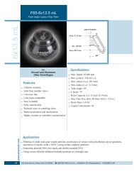
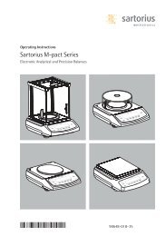
10 Installation and removal of the rotor<br />
A<br />
C<br />
D<br />
B<br />
• Clean the motor shaft (C) and the rotor drilling (A), and lightly grease the motor shaft<br />
afterwards. Dirt particles between the motor shaft and the rotor hinder a perfect seating<br />
of the rotor and cause an irregular operation.<br />
• Place the rotor vertically on the motor shaft. The motor shaft dog (D) has to fit in the<br />
rotor slot (B). The alignment of the groove is labelled on the rotor.<br />
• Tighten the rotor tension nut with the supplied wrench by turning in a clockwise<br />
direction.<br />
• Check the rotor for firm seating.<br />
• Loosening the rotor: Loosen the tension nut by turning in a counter clockwise direction,<br />
and turning until the working point for lifting. After passing the working point for lifting<br />
the rotor is loosened from the motor shaft cone. Turn the tension nut until the rotor is<br />
able to be lifted from the motor shaft.<br />
11 Loading the rotor<br />
Standard centrifuge containers of glass will not stand RCF values exceeding 4000 (DIN 58970, pg. 2).<br />
• Check the rotor for firm seating.<br />
With swing-out rotors all rotor positions must be lined with identical hangers. Certain hangers are marked with<br />
the number of the rotor position. These hangers may only be used in the respective rotor position. Hangers that<br />
are marked with a set number (e.g. S001/4) may only be used in the set.<br />
• The rotors and hangers may only be loaded symmetrically. The centrifuge containers have to be distributed<br />
evenly on all rotor positions. For authorised combinations see Chapter "Anhang/Appendix, Rotoren und<br />
Zubehör/Rotors and accessories".<br />
In the case of angle rotors all possible rotor positions must be loaded, see chapter "Anhang/Appendix, Rotoren<br />
und Zubehör/Rotors and accessories".<br />
Rotor is evenly loaded<br />
Not permitted!<br />
Rotor is not evenly loaded<br />
• On certain hangers, the weight of the maximum load or the weight of the maximum load and the maximum<br />
weight of the completely loaded hanger is specified. This weight may not be exceeded. In case of exception, see<br />
chapter " Centrifugation of materials or mixtures of materials with a density higher than 1.2 kg/dm 3 ".The weight<br />
specified for the maximum loading includes the total weight of adapter, frame, centrifuging container and content.<br />
• In containers with rubber inserts, the same number of rubber inserts must always be among the centrifuge<br />
containers.<br />
• Always fill the centrifuge containers outside of the centrifuge.<br />
• No liquid should be allowed to enter the centrifugal chamber during filling and swinging out of the hangers.<br />
• The maximum filling quantity for the centrifuge containers specified by the manufacturer must not be exceeded.<br />
• In order to maintain the weight differences within the centrifuge container as marginal as possible, a consistent<br />
fill level in the containers is to be heeded.<br />
12 Control and display devices<br />
See figure on page 2.<br />
Fig. 2:<br />
Display and operating panel<br />
12.1 Status symbols<br />
Lid open.<br />
Lid closed.<br />
14/60
EN<br />
Rotation indicator. The indication appears while the centrifuge is running as long as the rotor is turning.<br />
STOP<br />
LOCK 1,<br />
LOCK 2<br />
LOCK 4,<br />
LOCK 5<br />
PC, PC<br />
Centrifugation run stopped or finished. Indication after completion of the centrifugation run as long as the<br />
rotor is turning. The indicator flashes following an emergency stop.<br />
Keyswitch position (for centrifuges with keyswitch only).<br />
Program interlocking when serial communication provided (for centrifuges with serial communication only).<br />
Serial communication (for centrifuges with serial communication only).<br />
Operating errors or faults that occur are shown symbolically in the display (see Chapter "Faults").<br />
12.2 Control knob<br />
For setting the individual parameters.<br />
Turning anticlockwise reduces the value. Turning clockwise increases the value.<br />
12.3 Keys and set-up options<br />
t<br />
RCF<br />
Running time, parameter t/min:sec<br />
1. Parameter t/min: Adjustable from 1 - 999 min, in 1 min steps.<br />
2. Parameter t/ :sec Adjustable from 1 - 59 s, in 1 second steps.<br />
3. Continuous running "---:--"<br />
Interrogation of the integral RCF, parameter ∫RCF.<br />
n<br />
RCF<br />
1. Speed, parameter RPM<br />
A numerical value from 50 RPM up to the maximum speed of the rotor (n-max-Rotor) can be set. Maximum<br />
speed of the rotor, see Chapter "Anhang/Appendix, Rotoren und Zubehör/Rotors and accessories".<br />
Adjustable in steps of 10.<br />
2. Interrogation of the maximum speed of the rotor, parameter n-max-Rotor.<br />
1. Relative centrifugal force, parameter RCF/RZB<br />
A numerical value can be set, which gives a speed between 50 RPM and the maximum speed of the rotor<br />
(n-max-Rotor). Adjustable in steps of 1.<br />
2. Interrogation of the maximum RCF of the rotor, parameter RCF-max-Rotor.<br />
Run-up parameters<br />
1. Run-up steps, parameter 1-9. Step 9 = shortest run-up time, ... Step 1 = longest run-up time.<br />
2. Run-up time, parameter t min:sec. The time range that can be set is dependent upon the set speed.<br />
Run-down parameters<br />
1. Braking steps, parameter 0-9. R = linear braking curve, B = similar to an exponential braking curve.<br />
Step R9, B9 = short run-down time, ... Step R1, B1 = long run-down time, Step R0 = unbraked run-down.<br />
2. Run-down time, parameter<br />
t min:sec<br />
3. Brake de-energisation speed, parameter n (•) /RPM<br />
After reaching this speed, unbraked run-down occurs.<br />
. The time range that can be set is dependent upon the set speed.<br />
1. Temperature setpoint, parameter T/°C (for centrifuges with cooling only). Adjustable from -20°C to +40°C,<br />
in 1°C steps (heating/cooling option settable between -20°C and +60°C / +90°C). The lowest temperature<br />
that can be achieved is dependent upon the rotor (see Chapter "Anhang/Appendix, Rotoren und<br />
Zubehör/Rotors and accessories").<br />
2. Centrifuging radius, parameter r/mm. Entry in mm. Centrifuging radius, see Chapter "Anhang/Appendix,<br />
Rotoren und Zubehör/Rotors and accessories“.<br />
START<br />
1. Start centrifugation run. The rotation indicator appears.<br />
2. Acceptance of changes during the centrifugation run.<br />
STOP<br />
PROG<br />
Stop centrifugation run.<br />
The rotor decelerates with the preset run-down parameters. Pressing the key twice will initiate an emergency<br />
stop.<br />
Select program location, parameter PROG-Nr.<br />
RCL<br />
Calling up of programs.<br />
STO<br />
Saving of programs.<br />
89 programs can be saved (program locations 1 to 89). Note: The program locations "----" and 90 to 99 are<br />
used as automatic buffers (see Chapter "Automatic buffer"). No programs can be saved in these program<br />
locations.<br />
15/60
EN<br />
13 Entering centrifugation parameters<br />
It is only possible to enter a parameter when the input field is displayed inversely (dark background). An<br />
inverse input field will go off automatically after 10 seconds.<br />
13.1 Running time<br />
13.1.1 Time selection<br />
• Press the t key repeatedly until the parameter t/min: or t/ :sec is displayed. The input field will be displayed<br />
inversely.<br />
• Set the desired value by means of the control knob .<br />
13.1.2 Continuous running<br />
• Select the parameters t/min: and t/ :sec one after the other (see Chapter "Time selection"), and set both to zero<br />
using the control knob . "---:--" will be displayed in the input field.<br />
13.2 Speed (RPM)<br />
• Press the n key repeatedly until the parameter RPM is displayed and the input field is shown inversely.<br />
• Set the desired value by means of the control knob .<br />
13.3 Relative centrifugal force (RCF/RZB)<br />
• Press the RCF key repeatedly until the parameter RCF/RZB is displayed and the input field is shown inversely.<br />
• Set the desired value by means of the control knob .<br />
The centrifuging radius indicator will flash while the adjustment is being made.<br />
13.4 Run-up and run-down parameters<br />
The run-up and run-down parameters that have been set are displayed.<br />
x<br />
PROFIL<br />
y<br />
x: 1-9 = run-up step, t = run-up time<br />
y: R1-R9, B1-B9 = braking step, R0 = unbraked run-down, t = run-down time, n (•) = brake deenergisation<br />
speed<br />
13.4.1 Run-up step<br />
• Press the key repeatedly until the parameter 1-9 or t is displayed. The input field will be displayed<br />
inversely.<br />
• Set the desired step by means of the control knob .<br />
13.4.2 Run-up time<br />
min:sec<br />
• Press the key repeatedly until the parameter t is displayed. The input field will be displayed inversely.<br />
• Set the desired value by means of the control knob .<br />
If a run-up time is set that is longer than the running time, the centrifugation run will end before the set speed is<br />
reached.<br />
13.4.3 Braking step<br />
• Press the key repeatedly until the parameter 0-9 or<br />
t<br />
is displayed. The input field will be displayed<br />
inversely.<br />
• Set the desired step by means of the control knob .<br />
B-braking steps can only be set for special rotors.<br />
13.4.4 Run-down time<br />
If a brake de-energisation speed has been set, it is not possible to set a run-down time.<br />
• Press the key repeatedly until the parameter<br />
t min:sec is displayed. The input field will be displayed inversely.<br />
• Set the desired value by means of the control knob .<br />
16/60
EN<br />
13.4.5 Brake de-energisation speed<br />
• Press the key repeatedly until the parameter n (•) /RPM is displayed. The input field will be displayed inversely.<br />
• Set the desired value by means of the control knob .<br />
13.5 Radius/Temperature<br />
13.5.1 Radius<br />
• Press the key repeatedly until the parameter r/mm is displayed and the input field is shown inversely.<br />
• Set the desired value by means of the control knob .<br />
The value of the RCF/RZB adapts automatically when the radius is changed; this is shown by the indication flashing.<br />
13.5.2 Temperature (for centrifuges with cooling only)<br />
• Press the key repeatedly until the parameter T/°C is displayed and the input field is shown inversely.<br />
• Set the desired value by means of the control knob .<br />
13.6 Automatic buffer<br />
The buffer comprises the program locations "----" and 90 to 99. Every time a centrifugation run is started, modified<br />
centrifugation data are automatically stored in program location "----". The modified centrifugation data for the last 11<br />
centrifugation runs are stored in the buffer and can be called up (see Chapter "Calling up programs").<br />
14 Programming<br />
14.1 Entering / modifying programs<br />
• Set the desired parameters (see Chapter "Entering centrifugation parameters").<br />
• Press the PROG key in order to select the parameter PROG-Nr. The input field will be displayed inversely.<br />
• Set the desired program location by means of the control knob .<br />
If the program location indicator flashes, then this program location has already had centrifugation data assigned<br />
to it. In this case, set a free program location or overwrite the centrifugation data by continuing.<br />
• Press the STO key once to save the settings in the desired program location.<br />
Press the STO key twice to overwrite centrifugation data already stored.<br />
14.2 Calling up programs<br />
• Press the PROG key in order to select the parameter PROG-Nr. The input field will be displayed inversely.<br />
• Set the desired program location by means of the control knob .<br />
• Press the RCL key. The centrifugation data for the selected program location will be displayed.<br />
15 Centrifugation<br />
When the centrifuge is running, according to EN / IEC 61010-2-020, no persons, dangerous substances or<br />
objects may be within the safety margin of 300 mm around the centrifuge.<br />
If the permissible weight difference within the rotor loading has been exceeded, the drive shuts down during<br />
the start-up, and IMBALANCE / UNWUCHT is displayed.<br />
If the speed in the selected program is higher than the maximum speed of the rotor (n-max-Rotor), it will not<br />
be possible to start a centrifugation run. The message N > ROTOR MAX 96 will be displayed (see Chapter<br />
"Faults").<br />
A centrifugation run can be stopped at any time by pushing the key STOP .<br />
It is possible to switch over between RPM and RCF display at any time using the n and RCF keys. When<br />
working with the RCF display, it is necessary to enter the centrifuging radius.<br />
If OPEN OEFFNEN is displayed, a further operation of the centrifuge is only possible after opening the lid<br />
once.<br />
If R xx n-max xxxxx is displayed, then no centrifugation run has taken place as the rotor was changed<br />
beforehand, refer to Chapter " Rotor Identification ".<br />
• Switch on the mains supply switch. Switch position Ι.<br />
• Load the rotor and close the centrifuge lid.<br />
17/60
EN<br />
15.1 Centrifugation with time selection<br />
• Set the time or call up a program with a pre-set time (see Chapter "Entering centrifugation parameters" or<br />
"Calling up programs").<br />
• Press the START key. The rotation indicator will appear as long as the rotor is turning.<br />
• When the time has expired or if the centrifugation run is interrupted by pressing the STOP key, run-down will take<br />
place with the selected run-down parameters. When the rotor comes to a stop, the symbol will flash in the<br />
display until the lid is opened.<br />
During the centrifugation run, the speed of the rotor or the RCF value resulting from this, the sample temperature (for<br />
centrifuges with cooling only) and the remaining time will be displayed.<br />
15.2 Continuous running<br />
• Select the ---:-- symbol or call up a continuous running program (see Chapter "Entering centrifugation<br />
parameters" or "Calling up programs").<br />
• Press the START key. The rotation indicator will appear as long as the rotor is turning. The time count starts<br />
from 00:00.<br />
• Press the STOP key to stop the centrifugation run. Run-down will take place with the selected run-down<br />
parameters. When the rotor comes to a stop, the symbol will flash in the display until the lid is opened.<br />
During the centrifugation run, the speed of the rotor or the RCF value resulting from this, the sample temperature (for<br />
centrifuges with cooling only) and the time run will be displayed.<br />
16 Changing settings during the centrifugation run.<br />
The running time, the speed, the relative centrifugal force (RCF/RZB), the run-up and run-down parameters as well<br />
as the temperature (for centrifuges with cooling only) can be changed while the centrifuge is running.<br />
The parameters can only be changed one at a time and in succession.<br />
• Select the desired parameter and change the value using the control knob (see Chapter "Entering<br />
centrifugation parameters").<br />
• Press the START key. The modified setting will be stored in program location "----" (see Chapter "Automatic<br />
buffer"). The original program will not be overwritten.<br />
17 Integral RCF (∫RCF)<br />
The integral RCF (∫RCF) is a measure for the sedimentation effect (∫ n 2 dt). This numerical value is used to compare<br />
centrifugation runs. To interrogate the integral RCF, press and hold the RCF key.<br />
18 Displaying the maximum speed of the rotor<br />
• Press the n key repeatedly until the parameter RPM is displayed and the input field is shown inversely.<br />
• Press the n key once more and hold it pressed; the maximum speed of the rotor (n-max-Rotor) will be displayed.<br />
19 Displaying the maximum RCF of the rotor<br />
• Press the RCF key repeatedly until the parameter RCF/RZB is displayed and the input field is shown inversely.<br />
• Press the RCF key once more and hold it pressed; the maximum RCF of the rotor (RCF-max-Rotor) will be<br />
displayed.<br />
20 Emergency stop<br />
• Press the STOP key twice. The STOP symbol will flash in the display.<br />
In the case of an emergency stop, run-down takes place with braking step R9 (shortest run-down time). If braking<br />
step R0 was selected, the run-down time will be longer than with braking step R9 for technical reasons.<br />
18/60
EN<br />
21 Audible signal<br />
The audible signal sounds in accordance with the following philosophy:<br />
OFF • at 2 s intervals on the occurrence of a fault<br />
ON1 • at 2 s intervals on the occurrence of a fault<br />
• at 30 s intervals on completion of a centrifugation run and the rotor coming to rest.<br />
ON2 • at 2 s intervals on the occurrence of a fault<br />
• at 30 s intervals on completion of a centrifugation run and the rotor coming to rest.<br />
• every time a key is pressed<br />
The audible signal is silenced by opening the lid or pressing any key.<br />
The signal can be set as follows when the rotor is at standstill.<br />
• Open the lid.<br />
• Press and hold the t key for 8 seconds.<br />
After 8 seconds SOUND / BELL XXX will be displayed.<br />
• Set the desired function (OFF, ON1, ON2) by means of the control knob .<br />
• Press the START key to save the setting.<br />
∗∗∗ ok ∗∗∗ will be displayed briefly as a confirmation.<br />
22 Interrogating the operating hours<br />
It is only possible to interrogate the operating hours when the rotor is at standstill.<br />
• Open the lid.<br />
• Press and hold the t key for 8 seconds.<br />
After 8 seconds SOUND / BELL XXX will be displayed.<br />
• Press the t key once more.<br />
The operating hours (CONTROL: ) for the centrifuge will be displayed.<br />
The operating hours display will go off automatically after 10 seconds.<br />
23 Setting the date and time<br />
It is only possible to set the date and time when the rotor is at standstill.<br />
• Open the lid.<br />
• Press and hold the t key for 8 seconds.<br />
After 8 seconds SOUND / BELL XXX will be displayed.<br />
• Press the t key twice more.<br />
The date and time will be displayed (a: year, mon: month, d: day, h: hours, min: minutes).<br />
• Press the key repeatedly until the input field for the desired parameter is shown inversely.<br />
• Set the desired value by means of the control knob .<br />
• Press the START key to save the setting.<br />
∗∗∗ ok ∗∗∗ will be displayed briefly as a confirmation.<br />
• To exit the date and time set-up, press any key apart from the , t and START keys.<br />
24 Centrifugation data displayed after switching on.<br />
After switching on, the centrifugation data for program 1 or for the program last used will be displayed. This can be<br />
set as follows:<br />
• Open the lid.<br />
• Switch the mains supply switch off and on again. Switch position Ι.<br />
• Press the STOP key when the first visual change appears in the display (inverse display).<br />
PROGRAM 1, LAST PROGRAM will be displayed.<br />
• Set the desired function by means of the control knob .<br />
• Press the START key to save the setting.<br />
∗∗∗ ok ∗∗∗ will be displayed briefly as a confirmation.<br />
25 Immediate display of the centrifugation data after switching on<br />
• Switch on the mains supply switch. Switch position Ι.<br />
• Press any key apart from the STOP key when the first visual change appears in the display (inverse display). The<br />
centrifugation data will be displayed immediately.<br />
19/60
EN<br />
26 Key-operated switch (for centrifuges with key-operated switch only).<br />
The following program interlocks can be set by the key-operated switch:<br />
Left key position: LOCK 1 will be displayed.<br />
Programs can be called up but not changed.<br />
Right key position:<br />
Middle key position:<br />
LOCK 2 will be displayed.<br />
No programs can be called up or changed.<br />
no status display.<br />
No program interlock. Programs can be called up and changed.<br />
27 Program linking (for centrifuges with program linking only).<br />
Several centrifugation runs can be linked together with the help of the program linking function.<br />
27.1 Linking programs<br />
Program linking is only possible with programs in which run-up and braking steps have been set.<br />
Before linking, the programs must be stored in the desired sequence either by entering the program or by<br />
calling up the program (see Chapter "Programming").<br />
The program locations must be consecutive (e.g. program locations 10+11+12).<br />
1. Press the PROG key in order to select the parameter PROG-Nr. The input field will be displayed inversely.<br />
2. Set the program location for the first program (XX+) by means of the control knob .<br />
3. Press the RCL key. The centrifugation data for the selected program location will be displayed.<br />
4. Press the PROG key twice in order to select the parameter PR-PART. The input field will be displayed inversely.<br />
5. Press the STO key twice. The program will be linked and the program number for the next program location<br />
(+XX+) will be displayed.<br />
6. Press the RCL key twice. The centrifugation data for the selected program location will be displayed.<br />
7. Press the STO key twice. The program will be linked and the program number for the next program location<br />
(+XX+) will be displayed.<br />
8. Keep repeating steps 6 and 7 until all programs have been linked.<br />
9. Press the PROG key to exit. The program number for the last program (+XX) will be displayed.<br />
27.2 Changing program links<br />
• Call up the desired program (see Chapter "Calling up programs"), change the desired parameters (see Chapter<br />
"Entering centrifugation parameters"), and save the modified centrifugation data to the same program location<br />
(see Chapter "Entering / modifying programs"). As a result of saving, the program linking will be removed.<br />
• Re-link the programs (see Chapter "Linking programs").<br />
27.3 Centrifugation run with program linking<br />
• Press the PROG key twice in order to select the parameter PR-PART. The input field will be displayed inversely.<br />
• Set the program location for the first program (XX+) by means of the control knob .<br />
• Press the RCL key. The centrifugation data for the selected program location will be displayed.<br />
• Press the START key. The rotation indicator will appear as long as the rotor is turning.<br />
The run-up and braking steps for the program linking will be displayed:<br />
x<br />
PR-PART<br />
First program (XX+)<br />
x: Run-up step for the first program<br />
x<br />
x<br />
PR-PART<br />
y<br />
PR-PART<br />
Next program (+XX+)<br />
x: Run-up step for the next program<br />
Last program (+XX)<br />
x: Run-up step for the last program<br />
y: Braking step for the last program<br />
• When the time in the last program has expired, run-down will take place with the braking step of the last<br />
program. If the centrifugation run is interrupted by pressing the STOP key, run-down will take place with the<br />
braking step of the program running at the time.<br />
20/60
EN<br />
27.4 Deleting program linking<br />
• Press the PROG key in order to display the parameter PROG-Nr. The input field will be displayed inversely.<br />
• Set the program location for the first program (XX+) by means of the control knob .<br />
• Press the RCL key. The centrifugation data for the selected program location will be displayed.<br />
• Press the PROG key twice in order to display the parameter PR-PART. The input field will be displayed inversely.<br />
• Press the STO key twice.<br />
• Press the PROG key.<br />
28 Cooling (only in centrifuges with cooling)<br />
The temperature set-point can be adjusted from -20°C to +40°C. The lowest obtainable temperature is dependent on<br />
the rotor (see Chapter "Anhang/Appendix, Rotoren und Zubehör/Rotors and accessories"). If the actual temperature<br />
and the set temperature deviate more than 5 °C, the temperature value in the display will start to flash on and off.<br />
28.1 Standby-cooling<br />
With rotor standstill and closed lid the centrifugal chamber is cooled to the pre-selected temperature. The<br />
temperature set-point is shown in the display.<br />
28.2 Pre-cooling the rotor<br />
For rapid pre-cooling of the unloaded rotor and the accessories, it is recommended that the centrifuge is run with the<br />
continuous running settings and a speed of ca. 20% of the maximum rotor speed.<br />
29 Heating (only on centrifuges with heating/cooling option)<br />
During operation of the centrifuge the centrifuge chamber can be heated as required to the preselected temperature.<br />
The heating is switched off when the rotor is stationary.<br />
Risk of burning! The surface temperature of the heating element in the centrifugal chamber of the centrifuge<br />
can reach 500°C / 932°F. Do not touch the heating element.<br />
30 Relative centrifugal force (RCF)<br />
The relative centrifugal force (RCF) is given as a multiple of the acceleration of gravity (g). It is a unit-free value and<br />
serves to compare the separation and sedimentation performance.<br />
These values are calculated using the formula below:<br />
2<br />
⎛ RPM ⎞<br />
RCF<br />
RCF = ⎜ ⎟ × r × 1,118 ⇒ RPM =<br />
× 1000<br />
1000 ⎠ r × 1,118<br />
⎝<br />
RCF = relative centrifugal force<br />
RPM = rotational speed (revolutions per minute)<br />
r = centrifugal radius in mm = distance from the centre of the turning axis to the bottom of the centrifuge.<br />
For more on the centrifugal radius see the chapter ” Anhang/Appendix,<br />
Rotoren und Zubehör/Rotors and accessories”.<br />
The relative centrifugal force (RCF) stands in relation to the revolutions per minute and the centrifugal<br />
radius.<br />
21/60
EN<br />
31 Centrifugation of materials or mixtures of materials with a density higher than 1.2 kg/dm 3<br />
When centrifuging with maxim revolutions per minute the density of the materials or the material mixtures may not<br />
exceed 1.2 kg/dm 3 .<br />
The speed must be reduced for materials or mixtures of materials with a higher density.<br />
The permissible speed can be calculated using the following formula:<br />
Reduced speed (nred)<br />
=<br />
1.2<br />
Greater density [kg/dm³]<br />
x maximum<br />
speed [RPM]<br />
e.g.: maximum speed RPM 4000, density 1.6 kg/dm 3<br />
nred =<br />
1.2 kg/dm³<br />
1.6 kg/dm³<br />
x 4000 RPM = 3<strong>46</strong>4 RPM<br />
In the exceptional case that the maximum loading indicated on the hanger is exceeded, the speed must also be<br />
reduced.<br />
The permissible speed can be calculated using the following formula:<br />
Reduced speed (nred)<br />
=<br />
maximum load [g]<br />
x maximum<br />
actual load [g]<br />
speed [RPM]<br />
e.g.: maximum speed RPM 4000, maximum load 300 g, actual load 350 g<br />
nred =<br />
300 g<br />
350 g<br />
x 4000 RPM = 3703 RPM<br />
If in doubt you should obtain clarification from the manufacturer.<br />
32 Rotor Identification<br />
After every start of a centrifugation run the rotor utilised is identified.<br />
After a change of rotor the drive switches off and the rotor code (R xx) as well as the maximum rotational speed<br />
(n-max=xxxxx) of the rotor are displayed.<br />
A further operation of the centrifuge is only possible after pressing the START key.<br />
If, following a rotor change, the maximum speed of the rotor is less than the set speed, the speed is limited to<br />
the maximum speed of the rotor.<br />
33 Emergency release<br />
The lid cannot be opened during power failure. An emergency release has to be executed by hand.<br />
For emergency release disconnect the centrifuge from the mains.<br />
Open the lid only during rotor standstill.<br />
Only the plastic release pin provided may be used for emergency release.<br />
See figure on page 2.<br />
• Switch off the mains switch (switch position "0").<br />
• Look through the window in the lid to be sure that the rotor has come to a standstill.<br />
• Insert the release pin (see scope of supply) horizontally into the hole (Fig. 1, A). Insert the release pin up to the<br />
point at which the turning knob can be rotated to the left when the pin is pushed downwards.<br />
• Open the lid.<br />
34 Maintenance and servicing<br />
Pull the mains plug before cleaning.<br />
Before any other cleaning or decontamination process other than that recommended by the manufacturer is<br />
applied, the user has to check with the manufacturer that the planned process does not damage the device.<br />
• Centrifuges, rotors and accessories must not be cleaned in rinsing machines.<br />
• They may only be cleaned by hand and disinfected with liquids.<br />
• The water temperature must be between 20 – 25°C.<br />
• Only detergents/disinfectants may be used which:<br />
− have a pH between 5 - 8<br />
− do not contain caustic alkalis, peroxides, chlorine compounds, acids and alkaline solutions<br />
22/60
EN<br />
• In order to prevent appearances of corrosion through cleaning agents or disinfectants, the application guide from<br />
the manufacturer of the cleaning agent or disinfectant are absolutely to be heeded.<br />
34.1 Centrifuge (housing, lid and centrifuging chamber)<br />
34.1.1 Surface cleaning and care<br />
• Clean the centrifuge housing and the centrifuging chamber regularly, using soap or a mild detergent and a damp<br />
cloth if required. For one thing, this services purposes of hygiene, and it also prevents corrosion through<br />
adhering impurities.<br />
• Ingredients of suitable detergents:<br />
soap, anionic tensides, non-ionic tensides.<br />
• After using detergents, remove the detergent residue by wiping with a damp cloth.<br />
• The surfaces must be dried immediately after cleaning.<br />
• In the event of condensation water formation, dry the centrifugal chamber by wiping out with an absorbent cloth.<br />
• Lightly rub the rubber seal of the centrifuge chamber with talcum powder or a rubber care product after each<br />
cleaning.<br />
• The centrifuging chamber is to be checked for damage once a year.<br />
If damage is found which is relevant to safety, the centrifuge may no longer be put into operation. In this<br />
case, notify Customer Service.<br />
34.1.2 Surface disinfection<br />
• If infectious materials penetrates into the centrifugal chamber this is to be disinfected immediately.<br />
• Ingredients of suitable disinfectants:<br />
ethanol, n-propanol, isopropyl alcohol, glutardialdehyde, quaternary ammonium compounds.<br />
• After using disinfectants, remove the disinfectant residue by wiping with a damp cloth.<br />
• The surfaces must be dried immediately after disinfecting.<br />
34.1.3 Removal of radioactive contaminants<br />
• The agent must be specifically labelled as being an agent for removing radioactive contaminants.<br />
• Ingredients of suitable agents for removing radioactive contaminants:<br />
anionic tensides, non-ionic tensides, polyhydrated ethanol.<br />
• After removing the radioactive contaminants, remove the agent residue by wiping with a damp cloth.<br />
• The surfaces must be dried directly after removing the radioactive contaminants.<br />
34.2 Rotors and Attachments<br />
34.2.1 Cleaning and care<br />
• In order to prevent corrosion and material changes, rotors and accessories must be cleaned regularly with soap<br />
or a mild detergent and a damp cloth. Cleaning is recommended at least once a week. Contaminants must be<br />
removed immediately.<br />
• Ingredients of suitable detergents:<br />
soap, anionic tensides, non-ionic tensides.<br />
• After using detergents, remove detergent residue by rinsing with water (only outside of the centrifuge) or wipe off<br />
with a damp cloth.<br />
• The rotors and accessories must be dried directly after cleaning.<br />
• Angle rotors, container and hanger made of aluminium are to be lightly greased after drying using acid-free<br />
grease, e.g. vaseline.<br />
• In order to prevent corrosion as a result of moisture between the rotor and the motor shaft, the rotor should be<br />
disassembled and cleaned at least once a month, and the motor shaft should be lightly greased.<br />
• The rotors and the accessory parts have to be checked on a monthly basis for wear and corrosion.<br />
For swing-out rotors, it is important to check the area of the lifting lugs, for hangers, the grooves and the base<br />
should be checked for cracks.<br />
Rotors and attachments may no longer be utilised upon indication of wear and tear or corrosion.<br />
• Check the firm seating of the rotor on a weekly basis.<br />
23/60
EN<br />
34.2.2 Disinfection<br />
• If infectious material should get on the rotors or accessories, they must be appropriately disinfected.<br />
• Ingredients of suitable disinfectants:<br />
glutaraldehyde, propanol, ethyl hexanol, anionic tensides, corrosion inhibitors.<br />
• After using disinfectants, remove disinfectant residue by rinsing with water (only outside of the centrifuge) or wipe<br />
off with a damp cloth.<br />
• The rotors and accessories must be dried directly after disinfection.<br />
34.2.3 Removal of radioactive contaminants<br />
• The agent must be specifically labelled as being an agent for the removal of radioactive contaminants.<br />
• Ingredients of suitable agents for removing radioactive contaminants:<br />
anionic tensides, non-ionic tensides, polyhydrated ethanol.<br />
• After removing the radioactive contaminants, remove agent residue by rinsing with water (only outside of the<br />
centrifuge) or wipe off with a damp cloth.<br />
• The rotors and accessories must be dried directly after removing the radioactive contaminants.<br />
34.2.4 Trunnions<br />
With swing-out rotors the trunnions must be regularly lubricated (Hettich Lubricating Grease No. 4051) in order to<br />
ensure consistent swinging out of the hangers.<br />
34.2.5 Rotors and accessories with limited service lives<br />
The use of certain rotors, hangers and accessory parts is limited by time.<br />
These are marked with the maximum permitted number of operating cycles or with an expiration date and the<br />
maximum permitted number of operating cycles or just with the expiration date; e.g.:<br />
- "einsetzbar bis Ende: ΙV. Quartal 2011 / usable until end of: ΙV. Quarter 2011" or<br />
"einsetzbar bis Ende Monat/Jahr: 10/2011 / usable until end of month/year: 10/2011"<br />
- "Max. Lauf Zyklen / max. cycles: 40000".<br />
For safety reasons, rotors, hangers and accessory parts may no longer be used if either the indicated<br />
maximum number of operating cycles or the indicated expiration date has been reached.<br />
34.3 Autoclaving<br />
Swing-out rotors, angle rotors made of aluminium, suspension made of metal, lids with bio-containment as well as<br />
stands and reductions can be autoclaved at 121° C / 250°F (20 mins).<br />
Otherwise you must ask the manufacturer.<br />
No statement can be made about the degree of sterility.<br />
The lids of the rotors and containers must be removed prior to autoclaving.<br />
Autoclaving accelerates the ageing process of plastics. In addition, autoclaving may discolour plastics.<br />
We recommend that the packing rings of the bio-safety system be replaced after autoclaving.<br />
24/60
EN<br />
34.4 Centrifuge containers<br />
• With leakiness or after the breakage of centrifuging containers broken container parts and leaked centrifugation<br />
material are to be completely removed.<br />
• The rubber inserts as well as the plastic sleeves of the rotors are to be replaced after a glass breakage.<br />
Remaining glass splitters cause further glass breakage!<br />
• If this concerns infectious material, a disinfection process is to be executed immediately.<br />
35 Faults<br />
If the fault cannot be eliminated with the help of the fault table, please inform Customer Service.<br />
Please specify the type of centrifuge and the serial number. Both numbers can be found on the name plate of the<br />
centrifuge.<br />
Perform a MAINS RESET:<br />
− Switch off the mains switch (switch position "0").<br />
− Wait at least 10 seconds and then switch on the mains switch again (switch position "Ι").<br />
Message / fault Cause Remedy<br />
No display --- No voltage.<br />
− Check supply voltage.<br />
Overvoltage protection tripped out. − Mains switch ON.<br />
TACHO - ERROR 01 Faulty speedometer.<br />
− Open the cover.<br />
02 No rotor installed.<br />
Defective motor, frequency converter or<br />
− Switch off the mains switch<br />
(switch position "0").<br />
drive.<br />
− Wait at least 10 seconds.<br />
− Turn the rotor vigorously by hand.<br />
− Switch on the mains switch again<br />
(switch position "Ι"). The rotor<br />
must turn during switch-on..<br />
IMBALANCE /<br />
(03) * The rotor is unevenly loaded. − Open lid.<br />
UNWUCHT<br />
− Check the loading of the rotor,<br />
see chapter "Loading the rotor".<br />
− Repeat the centrifugation run.<br />
CONTROL - ERROR 04, Error in lid locking or lid closure.<br />
06 - 09<br />
N > MAX 05 Rotation too fast<br />
− Perform a MAINS RESET.<br />
N < MIN 13 Rotation too slow<br />
ROTORCODE 10 Incorrect rotor coding<br />
MAINS INTERRUPT (11) * Power failure during the centrifugation run. − Open lid.<br />
(The centrifugation run was not finished.) − Push START button.<br />
− Repeat the centrifugation run if<br />
necessary.<br />
VERSIONS-ERROR 12 Mismatch between electronic components<br />
SER I/O - ERROR 30 - 38 Error / defective interface<br />
POS - ERROR 40 - <strong>46</strong> Error / defective positioning or hatch drive<br />
° C * - ERROR 50 – 56, Error / defective cooling<br />
58<br />
LOCK - ERROR 57 Error / defective program locking<br />
− Perform a MAINS RESET.<br />
FU / CCI - ERROR 60 - 83 Error / defective motor control<br />
CONTROL-ERROR 26,<br />
90 – 95,<br />
97 - 99<br />
Error / defective control unit<br />
N > ROTOR-MAX 96 Speed in the selected program greater than<br />
the maximum speed of the rotor (n-max-<br />
Rotor).<br />
* Error number do not appear in the display.<br />
All error numbers can be read out via parameter 00634.<br />
−<br />
Check the set speed.<br />
Reduce the set speed<br />
25/60
EN<br />
36 Description for Robotic<br />
The loading hatch is placed in the centrifuge lid.<br />
The centrifuge opens the hatch by a gear motor.<br />
The precision of each rotor position is better than 0,6 mm.<br />
36.1 Operational modes<br />
36.1.1 Normal robotic operation<br />
The key-operated switch has to be in position LOCK 2 (right key position) and the key must be pulled off.<br />
Additionaly in the complete arrangement the centrifuge has to be protected against unauthorized penetration and<br />
manipulation.<br />
36.1.2 Adjusting and initializing operation respectively handling of the centrifuge without serial interface<br />
It is only allowed for skilled maintenance staff to work in the adjusting and initializing operation.<br />
After the adjusting and initializing operation the key-operated switch has to be in position LOCK 2<br />
(right key position) and the key must be pulled off.<br />
To protect the key against unauthorized access keep it in a save place.<br />
This is depending to key-operated switch position.<br />
STOP<br />
The STOP key on the control panel is always active.<br />
START<br />
The START key on the control panel is normaly active.<br />
This key can be locked via the PC with LOCK 5 (see chapter "Description of PARAMETER", Parameter 00633).<br />
Close and open the hatch by using the gear motor<br />
Only possible in key-operated switch position LOCK 1 (left key position).<br />
OPEN the hatch<br />
CLOSE the hatch<br />
Press key RCL<br />
Press key STO<br />
Notice: The hatch drive acts as long as the key is pressed.<br />
26/60
EN<br />
36.2 Introduction for serial operation<br />
36.2.1 HETTICH Centrifuge-BUS<br />
Setting of serial interface<br />
- 9600 Bit/s<br />
- Format: - 1 Start-Bit<br />
- 7 Data bit<br />
- 1 Paritybit (even parity)<br />
- 1 Stop-Bit<br />
Used transmission control and abbreviations:<br />
STX = 02 hex: Start of text<br />
ETX = 03 hex: End of text<br />
EOT = 04 hex: End of transmission<br />
ENQ = 05 hex: Enquiry of data<br />
ACK = 06 hex: Acknowledge<br />
NAK = 15 hex: Not acknowledged<br />
ADR = Address of the centrifuge Range: 'A' to 'Z' and '[' , '\' and ']'<br />
C = CODE = Parameter-Address -> 5 Byte ASCII (always 5-digits)<br />
= = 3D hex: spacer between CODE and VAL<br />
V = VALUE (VAL) = Value -> 4 Byte ASCII (always 4-digits)<br />
BCC = Binary Code Check = Checksum of the relevant data in hex.<br />
(EXOR – summary of the with BCC mraked bytes)<br />
36.2.2 Used telegrams:<br />
36.2.2.1 ENQUIRY-Telegram = transmission request<br />
data link to the addressed centrifuge establishment to transmit the value ( V=VAL ) of the parameter (C=CODE)<br />
PC EOT ADR C C C C C ENQ<br />
BCC-base<br />
Centrifuge ADR STX C C C C C = V V V V ETX BCC<br />
PC<br />
EOT<br />
36.2.2.2 SELECT-Telegram = data-, or command transmission<br />
Data transmission of value V to the parameter C of the addressed centrifuges.<br />
BCC-base<br />
PC EOT ADR STX C C C C C = V V V V ETX BCC<br />
Centrifuge ADR ACK or ADR NAK<br />
PC<br />
EOT<br />
The characters are transmitted hexadecimal coded. For a better readability here these characters are always<br />
displayed as ASCII-Symbols!<br />
27/60
EN<br />
Additional explanation for the protocol:<br />
ADR<br />
= centrifuge-address (see also section "Address of the Centrifuge")<br />
C<br />
V<br />
= Parameter-Code (Parameter-Address)<br />
5 digit CODE, the first two HEX digits are always 0<br />
e.g.: Parameter-Address of the target speed<br />
0 0 6 0 3<br />
= Parameter-Value<br />
4-digits VAL, VALUE which displays the contents.<br />
e.g.: 500 RPM<br />
0 1 F 4<br />
Always only hexadecimal coded characters are transmitted!<br />
36.3 Time behaviour for serial operation<br />
36.3.1 Time for one ENQUIRY-Telegram<br />
ENQUIRY from<br />
PC<br />
Reaction time Answer of the centrifuge Reaction time PC END of<br />
transmission<br />
8<br />
digits<br />
14<br />
digits<br />
1<br />
digit<br />
approx. 9 ms 20...150 ms approx. 16 ms 15 ms approx. 1 ms<br />
PC<br />
Centrifuge<br />
36.3.2 Time for one SELECT-Telegram<br />
PC<br />
Command for PC Reaction time Answer Reaction time PC END by PC<br />
centrifuge centrifuge<br />
15<br />
digits<br />
2<br />
digits<br />
1<br />
digit<br />
approx. 17 ms 20...150 ms approx. 2 ms 15 ms approx. 1 ms<br />
Centrifuge<br />
The reaction time of the centrifuge depends on the respective working order.<br />
A busy control-panel µP, e.g. during a centrifugation, uses more computing time and so the reaction time is up to 150<br />
ms. If there is on answer from the centrifuge after 150 ms, it can be assumed that there is a serial Error.<br />
In case of an error the telegram should be repeated 2 to 3 times. If there is still no answer after the third transmission<br />
attempt, the telegram has to be cancelled to examine the cause of the Error.<br />
28/60
EN<br />
Example for an ENQUIRY-Telegram:<br />
PC transmit to address 29: content of parameter 00604 (actual speed) required.<br />
EOT ADR C C C C C ENQ schematic<br />
EOT ] 0 0 6 0 4 ENQ ASCII<br />
04 5D 30 30 36 30 34 05 HEX<br />
Centrifuge with address 29 answer: content of parameter 00604 (actual speed) = 500<br />
BCC<br />
ADR STX C C C C C = V V V V ETX BCC schematic<br />
] STX 0 0 6 0 4 = 0 1 F 4 ETX ASCII<br />
5D 02 30 30 36 30 34 3D 30 31 <strong>46</strong> 34 03 7F HEX<br />
End of telegram by PC:<br />
EOT schematic<br />
EOT<br />
ASCII<br />
04 HEX<br />
Example for SELECT-Telegram:<br />
PC transmit, to address 29, Parameter 00603; rated speed 1500 RPM:<br />
BCC<br />
EOT ADR STX C C C C C = V V V V ETX BCC schematic<br />
EOT ] STX 0 0 6 0 3 = 0 5 D C ETX BCC ASCII<br />
04 5D 02 30 30 36 30 33 3D 30 35 44 43 03 09 HEX<br />
Centrifuge answers:<br />
ADR ACK or ADR NAK schematic<br />
] ACK or ] NAK ASCII<br />
5D 06 or 5D 15 HEX<br />
End of telegram by PC:<br />
EOT schematic<br />
EOT<br />
ASCIII<br />
04 HEX<br />
29/60
EN<br />
36.4 Address of the Centrifuge<br />
Each centrifuge that is being communicated with has to have its own address.<br />
The PC uses this address to communicate with the centrifuge. This serial address can be compared with the name of<br />
a person.<br />
Each address in a system can only be given ONCE. In the Hettich-BUS system there can be managed up to 29<br />
centrifuges.<br />
Address range:<br />
1. Address A = 41 hex<br />
2. Address B = 42 hex<br />
to<br />
26. Address Z = 5A hex<br />
and<br />
27. Address [ = 5B hex<br />
28. Address \ = 5C hex<br />
29. Address ] = 5D hex<br />
The address set ex works is the last one ( ] = 29. address ). This address must be correctly set by the customer.<br />
Starting with address "A", each centrifuge has to get its own address in ascending order.<br />
The order of addresses should not be interrupted as the PC would waste time for the query of an address not given.<br />
If the rotor is at standstill and the lid is opened, the address can be set in the following manner:<br />
• Switch the mains switch on.<br />
• Press the STOP key when the first visual change appears in the display (inverse display, background gets dark).<br />
PROGRAM 1, LAST PROGRAM will be displayed.<br />
• Press the STOP key so often until ADRESS ] will be displayed.<br />
• Set the desired address by means of the control knob .<br />
• Press the START key to save the setting.<br />
∗∗∗ ok ∗∗∗ will be displayed briefly as a confirmation.<br />
• To exit the menu press any key apart from the STOP and START key.<br />
36.5 Principle for serial communication<br />
The PC requires an available RS 232 interface. The enclosed Opto Data Box converts the signal from RS 232 into<br />
light signals. All the data will be transmitted by an fiber optic cable. With this kind of cable data can by transmitted<br />
absolutely clear of strays via hundreds of meters.<br />
• The key-operated switch has to be in position LOCK 2 (right key position). The centrifuge obeys commands<br />
of a PC only in position LOCK 2 (Turn key clockwise to end-position; display shows LOCK 2). That means the<br />
centrifuge accepts only the START and STOP key of the control panel, all other keys are blocked.<br />
• Centrifuges are terminals (slaves), they answer only if they get an ENQURIY or SELECT telegram from the<br />
PC.<br />
• Rhythm of request: Interrogation sequence of the parameter 00634 and 00640 should be at least all 5 sec.<br />
• Time delay between sequential protocols:<br />
During the run:<br />
>= 500 ms, that means only 1 protocol per sec.<br />
Centrifuge is in standstill: >= 250 ms, that means max. 2 protocols per sec.<br />
Take care for this cycles between the protocols, because the centrifuge needs this time for internal operations.<br />
• Command for positioning:<br />
When using a 2-times rotor it is only allowed to go to position 1 and 3.<br />
After a positioning command ( Pos 1....Pos 4 ) the centrifuge acknowledges this command with ACK. Then this<br />
command is stored in the control panel.<br />
Only after executing this command the next positioning command can be stored.<br />
The centrifuge acknowledges an new positioning command with ACK but it ignorates this command and do not<br />
store it.<br />
• If one of above mentioned positioning commands is transmitted and the centrifuge accepts it with ACK. Do not<br />
repeat it because this can cause sporadic the Error POS-ERROR 40.<br />
• After each centrifugation (at standstill) the centrifuge will positioning the rotor automatically on Rotor position 1.<br />
• Each rotor position (1 ... 4) will be fixed by the magnetic brake.<br />
After 10 minutes the brake release automatically that means if the last position is needed, the command for this<br />
position has to be sent again (see also section 36.11.2 to 36.11.5).<br />
30/60
EN<br />
• Program-Lock via serial interface<br />
To avoid complication by parameter setting at the control panel, the software is applied with an additional<br />
software locking.<br />
LOCK 4<br />
LOCK 5<br />
corresponds to the program lock LOCK 2 only START and STOP key are active.<br />
also START key is locked, only the STOP key is active.<br />
The centrifuge has to be in LOCK 5 by control via the serial interface of the PC.<br />
Recommendation for "newcomer":<br />
All the used centrifugation programs should be stored in the control panel.<br />
The most convenient way to input these programs is the input directly on the control panel by using the keys and the<br />
control knob (see section "Entering centrifuging data").<br />
For programming on the control panel the key-operated switch has to be in middle position (no LOCK in the display).<br />
36.6 Summary of centrifuge parameter<br />
Parameter Content Access R = read<br />
R/W = read/write<br />
00601 nominal run-time R/W<br />
00602 actual run-time R<br />
00603 nominal speed R/W<br />
00604 actual speed R<br />
00605 maximum speed of rotor R<br />
00606 nominal-RCF R/W<br />
00607 actual-RCF R<br />
00608 maximum-RCF of rotor R<br />
00609 ∫ RCF/RZB-actual 1.word MSW R<br />
00610 ∫ RCF/RZB-actual 2.word LSW R<br />
00611 Run-up R/W<br />
00612 Run-down ( brake ) R/W<br />
00613 minimum Run-up time R<br />
00614 maximum Run-up time R<br />
00615 minimum Run-down time R<br />
00616 maximum Run-down time R<br />
00617 Brake switch off speed R/W<br />
00618 nominal value of temperature R/W<br />
00619 actual value of temperature R<br />
00620 Radius R/W<br />
00630 Program-Info R<br />
00631 Program-commands from PC R/W<br />
00632 Information about centrifuge R<br />
00633 Set-commands from PC R/W<br />
00634 State of centrifuge 1 R<br />
00635 State of centrifuge 2 R<br />
00636 Software-version of control panel R<br />
00639 Error reset and position 1 adjustment R/W<br />
00640 State of positioning<br />
Command for positioning<br />
R<br />
R/W<br />
00685 SIOF (Serial Input Output Failure)-state R<br />
31/60
EN<br />
36.7 General format of parameter content<br />
V V V V<br />
MSD LSD MSD LSD<br />
Bit 3...0 3...0 3...0 3...0 = 4 digit<br />
Bit 7....... ........0 7...... .........0 = 2 byte<br />
Bit 15............................... ....0 = 1 word<br />
byte 2 = LOW-byte = LSB<br />
byte 1 = HIGH-byte = MSB<br />
Explanation: V: VAL = Value<br />
MSD/LSD: Most/Least significant Digit (Digit = Nibble = half byte)<br />
MSB/LSB: Most/Least significant Byte<br />
MSb/LSb: Most/Least significant Bit<br />
Values are send or received in principle as 4 –digit characters.<br />
Each digit has a range: from 30 hex = ‘0’ to 39 hex = ‘9’<br />
and from 41 hex = ‘A’ to <strong>46</strong> hex = ‘F’.<br />
The information (VAL) of one parameter can cover the range 0000 hex to FFFF hex<br />
(0 up to 65535) with one transmission.<br />
The following parameter are hexadecimal coded:<br />
• Times 00601, 00602, 00613, 00614, 00615 and 00616<br />
• Speed 00603, 00604, 00605 and 00617<br />
• RCF 00606, 00607 and 00608<br />
• Radius 00620<br />
• Temperature 00618, 00619 (with scale, to prevent negative values)<br />
• Software-Version 00636<br />
Some informations are bit coded and / or numeral coded,<br />
e.g. Parameter 00630 and 00631:<br />
Byte 1 Byte 2<br />
7 1 = bit-coded 7 MSb numeral 2 Bit<br />
6 MSb numeral 7 Bit 6 LSb numeral 2 Bit<br />
5 numeral 7 Bit 5 1 = bit-coded<br />
4 numeral 7 Bit 4 1 = bit-coded<br />
3 numeral 7 Bit 3 1 = bit-coded<br />
2 numeral 7 Bit 2 1 = bit-coded<br />
1 numeral 7 Bit 1 1 = bit-coded<br />
0 LSb numeral 7 Bit 0 1 = bit-coded<br />
bit 7 bit 6 and bit 7<br />
bit-information<br />
numeral (2bit)<br />
bit 6 to Bit 0 range 0 ... 3<br />
numeral (7bit) bit 5 to bit 0<br />
range: 0 ... 127 (0 ... 7F hex )<br />
bit-Information<br />
Almost all functions offered by the control panel, can be called up via the interface.<br />
In the following chapter the most important commands and inquiries which are necessary for the positioning are<br />
presented:<br />
• START and STOP<br />
• Open and close the hatch<br />
• Move rotor to position 1 to 4<br />
• Call up stored programs<br />
32/60
EN<br />
36.8 Introduction in the most important parameters for serial drive of the centrifuge<br />
(This chapter shows only a short introduction.) All details will be described in the following chapter "Description of<br />
PARAMETER". In chapter "Example for enquiry and command" procedures and examples for serial operation are<br />
mentioned.<br />
36.8.1 Parameter for positioning (00640):<br />
Commands (Byte 2)<br />
7 MSb Lid control-bit 3<br />
6 Lid control-bit 2<br />
5 Lid control-bit 1<br />
4 LSb Lid control-bit 0<br />
3 1 = Go to position 4<br />
2 1 = Go to position 3<br />
1 1 = Go to position 2<br />
0 1 = Go to position 1<br />
• Open the hatch<br />
In Byte 2 are used Bit 4-7<br />
SELECT-Command to 00640 with 0060 hex<br />
Lid control-bit 1 and 2 set = Bit 5 and Bit 6 ( 6 hex )<br />
The lid control-bits will be reset , after command execute.<br />
• Close the hatch<br />
In Byte 2 are used Bit4-7<br />
SELECT-command to 00640 with 0070 hex<br />
Lid control-bits 0, 1 and 2 are set = Bit 4, Bit 5 and Bit 6 ( 7 hex )<br />
The lid control-bits will be reset , after command execute.<br />
• Go to position<br />
In byte 2 are used bit (0 –3)<br />
Position 1 Bit0 set = 1 hex → SELECT-command for: 00640 with 0001 hex<br />
Position 2 Bit1 set = 2 hex → SELECT-command for: 00640 with 0002 hex<br />
Position 3 Bit2 set = 4 hex → SELECT-command for: 00640 with 0004 hex<br />
Position 4 Bit3 set = 8 hex → SELECT-command for: 00640 with 0008 hex<br />
When using a 2-times rotor it is only allowed to go to position 1 and 3.<br />
State-Informations (Byte 1)<br />
7 1 = Magnetic brake is active<br />
6 1 = Hatch is open (from Software version 4.006)<br />
5 1 =<br />
4 1 = Hatch is closed<br />
3 1 = Rotor in position 4<br />
2 1 = Rotor in position 3<br />
1 1 = Rotor in position 2<br />
0 1 = Rotor in position 1<br />
The state bits from the control panel are set as long as the status is active<br />
From software version 4.006:<br />
hatch is open<br />
00634 Byte 2<br />
00640 Byte 1 Bit 6 = 1<br />
hatch is closed<br />
Bit 0 = 0<br />
&& Bit 4 = 1<br />
Up to software version 4.005:<br />
00634 Byte 2<br />
00640 Byte 1<br />
00640 Byte 2<br />
hatch is open<br />
Bit 4 = 0<br />
&& Bit 5 = 0<br />
&& Bit 6 = 0<br />
If the hatch is complete open, the command bits will be reset.<br />
hatch is closed<br />
Bit 0 = 0<br />
&& Bit 4 = 1<br />
33/60
EN<br />
36.8.2 Parameter for centrifuge state (00634)<br />
Byte 1:<br />
7 1 = Centrifuge Error (Error-no. in bit 0...6)<br />
6 MSb<br />
5 7-bit digit:<br />
4 − Centrifuge-Error no. (when bit 7 = 1),<br />
3 or<br />
2 − just called program number, shown in display,<br />
1 if no Error (bit 7 = 0)<br />
0 LSb<br />
Byte 2:<br />
7 1 = State has changed<br />
6 MSb Program-ID (see 00631)<br />
5 LSb Program-ID (see 00631)<br />
4 1 = Run-down<br />
3 1 = Centrifugation<br />
2 1 = Run-up<br />
1 1 = Stand still<br />
0 1 = Lid open<br />
• Lid and hatch is closed (machine is closed)<br />
Byte 2 Bit 0 is reset.<br />
Bit is reset, if the lid and the hatch is closed.<br />
• Lid or hatch is open (machine is open)<br />
Byte 2 Bit 0 is set.<br />
Bit is set, as soon as the lid or hatch is open. This bit corresponds to the lid indication on the control panel.<br />
• Standstill of centrifuge, lid or hatch can be opened<br />
Byte 2 Bit 1 is set.<br />
• Centrifuge in run-up<br />
Byte 2 Bit 2 is set.<br />
• Centrifuge in run, nominal speed reached<br />
Byte 2 Bit 3 is set.<br />
• Centrifuge in run-down<br />
Byte 2 Bit 4 is set.<br />
• Program-ID<br />
Byte 2 Bit 5 and 6 (binary coded, range 0 – 3)<br />
0: "normal" centrifuging-program<br />
1-3: ID for program sequence (PR-PART)<br />
1 = Start of program<br />
2 = Middle part of program<br />
3 = End of program<br />
e.g: One program sequence which consists of 4 program parts<br />
1. Part<br />
= 1<br />
Middle-Part<br />
= 2<br />
Middle-Part<br />
= 2<br />
End-Part<br />
= 3<br />
34/60
EN<br />
• Modification<br />
Parameter 00634 Byte 2, Bit 7<br />
This bit is set by the centrifuge, when recognising the following:<br />
1. Rotor changed<br />
2. Hardware-Lock (Key-operated-switch) changed<br />
3. Centrifuge started by a user using the control panel.<br />
4. Centrifuge stopped by a user using the control panel.<br />
5. Control panel recognises standstill after a centrifugation<br />
6. Centrifuge stopped with an error message<br />
After reading parameter 00634 by PC, this bit is cleared automatically by the control panel.<br />
• Numerical Information<br />
Parameter 00634 Byte 1, Bit 0 to 6<br />
The information is binary coded only bit 0 to bit 6 within a range up to<br />
127 = FF HEX.<br />
Either the actual program no. (bit 7 = 0) or the centrifuge error number is stored (bit 7 = 1).<br />
If it is a program or an error number depends on bit 7 (see next item).<br />
• Program-, or Error-Information<br />
If bit 7 is cleared, the current program number is set in same byte in bit 0 to bit 6.<br />
If bit 7 is set, the centrifuge stops with an error message. Bit 0 to 6 contain the current error number.<br />
36.8.3 Control commands for centrifugation<br />
The following commands are available via parameter 00633.<br />
• START<br />
SELECT-Command on parameter: 00633 with 0042 hex (set Start-bit and LOCK 4-bit).<br />
• STOP<br />
SELECT-Command on parameter: 00633 with 0001 hex (set Stop-bit).<br />
Only in case of emergency or in continuous run- mode the centrifuge should be stopped using the serial<br />
interface. In run-time the centrifuge stopped at end of running time.<br />
• RCL Program<br />
This correspond to press the RCL key on the control panel (an already stored program is recalled into the display,<br />
so that user is able to start it).<br />
1. Write to the parameter 00631 Byte 1, Bit 0 to Bit 6 the program number (pp). Possible program numbers 0 to<br />
99 and 100 (100 = program “----“).<br />
2. Set Parameter 00631 Byte 2, Bit 2.<br />
→ SELECT-command on parameter: 00631 with program number (pp)04 hex .<br />
36.8.4 Special functions: ACK, NAK and SIOF<br />
• If one centrifuge is answering with NAK to a telegram, the SIOF parameter (00685) has to read –out. The<br />
enclosed Info-bit will be reset with the read-out of the parameter.<br />
• Only with deleted bits in SIOF, the centrifuge will accept an order by SELECT.<br />
• SIOF-Bits will be set:<br />
• after switch on the centrifuge (mains reset)<br />
• by ENQUIRY a non existent parameter<br />
• by SELECT a non existent parameter<br />
• by SELECT a "read only" parameter<br />
• by SELECT non vaild values<br />
• by SELECT to parameter 00631, in case of overwriting an existing program (safety procedure).<br />
• With read-out SIOF:<br />
• a serial interface Error can be detected.<br />
• enable serial interface for SELECT-telegrams. With SIOF-enquiry all SIOF-Error-bit will be reset by the<br />
centrifuge.<br />
35/60
EN<br />
36.9 Description of PARAMETER<br />
Parameter-No.: 00601 Set run-time Access Read/Write<br />
Structure:<br />
MSD LSD MSD LSD<br />
time LSB<br />
time MSB<br />
Input:<br />
Range:<br />
Seconds<br />
0 = continuos run, time run = 1 up to 59,999 sec (999min:59sec)<br />
Parameter-No.: 00602 Actual run-time Access Read<br />
Structure:<br />
MSD LSD MSD LSD<br />
time LSB<br />
time MSB<br />
Display:<br />
Range:<br />
Seconds<br />
0 up to 59,999 sec (999 min:59 sec)<br />
Parameter-No.: 00603 Set-speed Access Read/Write<br />
Structure:<br />
MSD LSD MSD LSD<br />
Input: RPM = revolutions per minute<br />
Range: 50 up to max. Rotor-speed (see parameter 00605)<br />
Nominal speed LSB<br />
Nominal speed MSB<br />
Parameter-No.: 00604 Actual-speed Access Read<br />
Structure:<br />
MSD LSD MSD LSD<br />
Actual speed LSB<br />
Actual speed MSB<br />
Display:<br />
Range:<br />
RPM = Revolution Per Minute<br />
50 up to 20,000 RPM<br />
Parameter-No: 00605 Maximum rotor speed Access Read<br />
Structure:<br />
MSD LSD MSD LSD<br />
max. speed LSB<br />
max. speed MSB<br />
Display:<br />
Range:<br />
RPM = Revolutions Per Minute<br />
This value depends on the used rotor<br />
50 up to 20,000 RPM<br />
36/60
EN<br />
Parameter-No.: 00606 Set RCF/RZB Access Read/Write<br />
Structure:<br />
MSD LSD MSD LSD<br />
Input: RCF; Number without dimensions (multiple gravity)<br />
Range: 1 up to max. Rotor-RCF (see Parameter 00608)<br />
RCF LSB<br />
RCF MSB<br />
RCF-Formula:<br />
RCF ≈ 1,118×<br />
r ×<br />
⎛<br />
⎜<br />
⎝<br />
n<br />
1000<br />
⎟ ⎠<br />
⎞<br />
2<br />
r = radius in mm<br />
n = speed in RPM<br />
Parameter-No.: 00607 Actual-RCF/RZB Access Read<br />
Structure:<br />
MSD LSD MSD LSD<br />
RCF LSB<br />
RCF MSB<br />
Display:<br />
Range:<br />
Number without dimensions (multiple gravity)<br />
1 up to 30,000 RCF<br />
Parameter-No.: 00608 Maximum Rotor-RCF Access Read<br />
Structure:<br />
MSD LSD MSD LSD<br />
RCF LSB<br />
RCF MSB<br />
Display: Number without dimensions (multiple gravity)<br />
The value depends on the used rotor (max. rotor speed 00605) and radius 00620<br />
Range: 1 up to 30,000<br />
Description: ∫ RCF/RZB : float-number Format according to IEEE-754-Standard<br />
(width = 32 Bit)<br />
The complete information has to be determined by two parameters<br />
Parameter-No.: 00609 ∫ RCF/RZB 1.Word MSW Access Read<br />
Structure:<br />
MSD LSD MSD LSD<br />
31--------------------Bit-------------------16<br />
RCF LSB<br />
RCF MSB<br />
37/60
EN<br />
Parameter-No.: 00610 ∫ RCF/RZB 2.Word LSW Access Read<br />
Structure:<br />
MSD LSD MSD LSD<br />
RCF LSB<br />
RCF MSB<br />
15---------------------Bit--------------------0<br />
!! There are only values, therefore bit 31 is always 0 !!<br />
Bit 31 : sign ( 0 = positive, 1=negativ )<br />
Bit 30...23 : Exponent ( two’s complement with offset 127 dezimal )<br />
Bit 23 = 2 0<br />
Bit 24 = 2 1<br />
Bit 25 = 2 2<br />
Bit 26 = 2 3<br />
Bit 27 = 2 4<br />
Bit 28 = 2 5<br />
Bit 29 = 2 6<br />
Bit 30 = 2 7<br />
Bit 22...0 : normalised mantissa ( range 1...2 )<br />
Number 1 always exist and is not stored as a Bit.<br />
Bit 22 = 2 -1 = 0.5<br />
Bit 21 = 2 -2 = 0.25<br />
Bit 20 = 2 -3 = 0.125<br />
Bit 19 = 2 -4 = 0.0625<br />
etc<br />
Bit 0 = 2 -23<br />
Commutation formula: X = (-1) sign Exponent -127<br />
* Mantissa * 2<br />
38/60
EN<br />
Parameter-No.: 00611 Run-up Access Read/Write<br />
Structure:<br />
MSD LSD MSD LSD<br />
Byte 1<br />
7 1= level 0= time<br />
6 MSB ( Bit 14 )<br />
5<br />
4<br />
3 7-bit digit MSB<br />
2<br />
1<br />
0<br />
Byte 2<br />
7<br />
6<br />
5<br />
4 8-bit digit LSB<br />
3<br />
2<br />
1<br />
0 Lsb ( Bit 0 )<br />
Run-up parameter Byte 2<br />
Run-up parameter Byte 1<br />
1. Possibility: Run-up-level<br />
Run-up level, if Byte 1 -Bit 7- =1<br />
Range: 1 up to 9<br />
2. Possibility: Run-up time<br />
Run-up time, if Byte 1 -Bit 7- =0<br />
Time in second<br />
range: 1 up to 5,999 seconds ( 99 min : 59 sec )<br />
Values out of minimum or maximum are automatically set to the minimum or maximum<br />
value.<br />
Minimum- / maximum-value: see parameter 00613 and 00614<br />
Conversion from level to the corresponding time or reverse:<br />
Here is a table necessary to allocate level and time to each centrifuge and each rotor.<br />
39/60
EN<br />
Parameter-No.: 00612 Run-down Access Read/Write<br />
Structure:<br />
MSD LSD MSD LSD<br />
Run-down parameter Byte 2<br />
Run-down parameter Byte 1<br />
Byte 1<br />
7 1= Level 0= Time<br />
6 Msb ( Bit 14 )<br />
5<br />
4<br />
3 7-bit digit MSB<br />
2<br />
1<br />
0<br />
Byte 2<br />
7<br />
6<br />
5<br />
4 8-bit digit LSB<br />
3<br />
2<br />
1<br />
0 Lsb ( Bit 0 )<br />
1. Possibility: run-down level<br />
run-down level, if Byte 1 -Bit 7- =1<br />
range: 0 up to 9<br />
2. possibility: run-down time<br />
run-down time, if Byte 1 -Bit 7- =0<br />
time in second<br />
range: 1 up to 5,999 second ( 99 min : 59 sec )<br />
Values out of minimum or maximum are automatically set to the minimum or maximum<br />
value.<br />
Minimum- / maximum-value: see parameter 00615 and 00616<br />
Conversion from level to the corresponding time or reverse:<br />
Here is a table necessary to allocate level and time to each centrifuge and each rotor.<br />
40/60
EN<br />
Parameter-No.: 00613 Minimum run-up-time Access Read<br />
Parameter-No.: 00614 Maximum run-up-time Access Read<br />
Parameter-No.: 00615 Minimum run-down-time Access Read<br />
Parameter-No.: 00616 Maximum run-down-time Access Read<br />
Structure:<br />
MSD LSD MSD LSD<br />
Byte 1<br />
7 1= ( not used )<br />
6 Msb ( Bit 14 )<br />
5<br />
4<br />
3 7-bit digit MSB<br />
2<br />
1<br />
0<br />
Byte 2<br />
7<br />
6<br />
5<br />
4 8-bit digit LSB<br />
3<br />
2<br />
1<br />
0 Lsb ( Bit 0 )<br />
Time LSB<br />
Time MSB<br />
Display: Time in seconds<br />
Range: 1 up to 5,999 seconds ( 99 min : 59 sec )<br />
Parameter-No.: 00617 Brake-switch-off-speed Access Read/Write<br />
Structure:<br />
MSD LSD MSD LSD<br />
speed LSB<br />
speed MSB<br />
Display:<br />
Range:<br />
Speed (RPM), at which the centrifuge runs down without braking.<br />
50 up to Nominal-Speed (00603) (max. 20,000 RPM)<br />
Only values lower than the nominal speed have to be transferred via the interface.<br />
Parameter-No.: 00618 Set -Temperature Access Read/Write<br />
Structure:<br />
MSD LSD MSD LSD<br />
Input: Temperature in degree Celsius<br />
Range: Cooled centrifuges: -20 up to +40 °C<br />
Heated/Cooled centrifuges: -20 up to +60 °C<br />
Format: Data is transmitted standardised: with offset 25° (T min = 25)<br />
see also 00619 actual temperature<br />
Formula: transmitted data = (Nominal value + T min ) *2<br />
Nominal temperature<br />
always 00<br />
41/60
EN<br />
Parameter-No: 00619 Temperature-actual value Access Read<br />
Structure:<br />
MSD LSD MSD LSD<br />
Display: Temperature value in Celsius<br />
Range: -25 up to +102 °C<br />
Format: Data is transmitted standardised: with offset 25° (T min = 25)<br />
see also 00619 actual temperature<br />
Formula: transmitted data = (Nominal value - T min<br />
) *2<br />
actual temperature<br />
always 00<br />
e.g.:<br />
-25°C = 0X00<br />
-10°C = 0X1E<br />
+40°C = 0X82<br />
+102°C = 0XFE<br />
Parameter-No.: 00620 Radius Access Read/Write<br />
Structure:<br />
MSD LSD MSD LSD<br />
Range: 1 up to 500<br />
Radius (LSB)<br />
Radius (MSB)<br />
The range of the radius is not checked by the centrifuge. The correct radius has to be limited by the PC: Maximum<br />
radius <strong>ROTANTA</strong> <strong>46</strong> = 220 mm<br />
Parameter-No.: 00630 Program-Info Access Read<br />
Structure:<br />
MSD LSD MSD LSD<br />
Program-Info<br />
Program-Number (0 up to 99)<br />
Byte 1<br />
7 1 = (not used)<br />
6 MSb<br />
5<br />
4<br />
3 7-bit digit, which indicates the program-number,<br />
2<br />
1<br />
0 LSb<br />
Byte 2 Information from control panel (centrifuge)<br />
7 MSb Programm-ID<br />
6 LSb Program-ID<br />
5 1 =<br />
4 1 = PROG already exists (security bit)<br />
3 1 = Program stored (STO)<br />
2 1 = Program recalled (RCL)<br />
1 1 =<br />
0 1 = PROG written to serial parameter<br />
42/60
EN<br />
Parameter-No.: 00631 Program-command from PC Access Read/Write<br />
Structure:<br />
MSD LSD MSD LSD<br />
Program-command<br />
Program-number (0 up to 99)<br />
Byte 1<br />
7 1 = (not used)<br />
6 MSb<br />
5<br />
4<br />
3 7-bit digit, which indicates the program number,<br />
2<br />
1<br />
0 LSb<br />
Byte 2 Program-command from PC<br />
7 MSb Program-ID<br />
6 LSb Program-ID<br />
5 1 =<br />
4 1 = PROG overwrite (overwrite confirmation)<br />
3 1 = STO Program<br />
2 1 = RCL Program<br />
1 1 = Hand over program-ID<br />
0 1 = Write program in serial parameter<br />
Bit 7 Bit 6 Program-ID:<br />
0 0 Profile (standalone)<br />
0 1 Sequential program first part<br />
1 0 Sequential program middle part<br />
1 1 Sequential program last part<br />
Parameter-No: 00632 Centrifuge-ID Access Read<br />
Structure:<br />
MSD LSD MSD LSD<br />
Code plug Byte 2<br />
Code plug Byte 1<br />
Byte 1<br />
7 MSb Jumper A7 Machine Bit 3<br />
6 Jumper A6 Machine Bit 2<br />
5 Jumper A5 Machine Bit 1<br />
4 LSb Jumper A4 Machine Bit 0<br />
3 1 = Jumper A3<br />
2 MSb Jumper A2 Cooling Bit 2<br />
1 Jumper A1 Cooling Bit 1<br />
0 LSb Jumper A0 Cooling Bit 0<br />
Byte 2<br />
7 1 = Jumper B7<br />
6 1 = Jumper B6 Sequential programs possible<br />
5 1 = Jumper B5<br />
4 1 = Jumper B4 Serial communication PC to Centrifuge<br />
3 1 = Jumper B3<br />
2 1 = Jumper B2 Service-Mode 3<br />
1 1 = Jumper B1 Service-Mode 2<br />
0 1 = Jumper B0 Service-Mode 1<br />
For <strong>ROTANTA</strong> <strong>46</strong> <strong>RSC</strong> <strong>ROBOTIC</strong>: The result of the telegram has to be as the following:<br />
ADR STX 0 0 6 3 2 = 3 1 1 X ETX BCC<br />
or with sequential program:<br />
ADR STX 0 0 6 3 2 = 3 1 5 X ETX BCC<br />
(X : Value can depends to the set service jumpers)<br />
43/60
EN<br />
Parameter-No: 00633 Control-command Access Read/Write<br />
Structure:<br />
MSD LSD MSD LSD<br />
Control-command<br />
Command for Report<br />
Byte 1<br />
7 1 = Report requested<br />
6 1 = Report terminated<br />
5 1 =<br />
4 1 =<br />
3 1 =<br />
2 1 =<br />
1 1 =<br />
0 1 =<br />
Bit "Report desired" has a static function, i.e. it is set by the PC, it has to be waited after each centrifugation for bit<br />
"terminated". Then the centrifuge can be restarted again.<br />
Byte 2 Control-Command<br />
7 1 = LOCK 5 (Input locked, excluding STOP)<br />
6 1 = LOCK 4 (Input locked = LOCK 2)<br />
5 1 =<br />
4 1 =<br />
3 1 = Modification of nominal value is required<br />
2 1 =<br />
1 1 = START<br />
0 1 = STOP<br />
Parameter-No: 00634 State of centrifuge 1 Access Read<br />
Structure:<br />
MSD LSD MSD LSD<br />
State of centrifuge / control panel<br />
Error of program-number<br />
Byte 1:<br />
7 1 = Centrifuge Error (Error no. in Bit 0...6)<br />
6 MSb<br />
5 7-bit digit:<br />
4 − Centrifuge-Error (Bit 7 = 1),<br />
3 or<br />
2 − just called program no. is indicated in display,<br />
1 if no Error (Bit 7 = 0)<br />
0 LSb<br />
Byte 2 Status Centrifuge / control panel<br />
7 1 = State has changed<br />
6 MSb Program-ID (see 00631)<br />
5 LSb Program-ID (see 00631)<br />
4 1 = Run-down<br />
3 1 = Centrifugation<br />
2 1 = Run-up<br />
1 1 = Stand still<br />
0 1 = Lid or/and hatch open<br />
44/60
EN<br />
Parameter-No.: 00635 State of centrifuge 2 Access Read<br />
Structure:<br />
MSD LSD MSD LSD<br />
State of centrifuge<br />
Byte 1<br />
7 1 =<br />
6 1 =<br />
5 1 =<br />
4 1 =<br />
3 1 =<br />
2 1 =<br />
1 1 =<br />
0 1 =<br />
Byte 2 State of centrifuge<br />
7 MSb Rotor code Bit 3<br />
6 Rotor code Bit 2<br />
5 Rotor code Bit 1<br />
4 LSb Rotor code Bit 0<br />
3 1 =<br />
2 MSb Lock-state Bit 2<br />
1 Lock-state Bit 1<br />
0 LSb Lock-state Bit 0<br />
Lock-state:<br />
1 = LOCK 1<br />
2 = LOCK 2<br />
3 = LOCK 3<br />
4 = LOCK 4<br />
5 = LOCK 5<br />
Rotor code:<br />
Rotor code 0<br />
Rotor code 1<br />
up to<br />
Rotor code 15<br />
Parameter-No.: 00636 Software-Version Access Read<br />
Structure:<br />
MSD LSD MSD LSD<br />
Example:<br />
Software-Version 1.234 is stored as follows: Byte 1: 12, Byte 2: 34<br />
Software-Vers. Byte 2<br />
Software-Vers. Byte 1<br />
45/60
EN<br />
Parameter-Nr: 00639<br />
ERROR RESET<br />
and<br />
POSITION 1 ADJUSTMENT<br />
ACCESS Read/Write<br />
ERROR RESET via serial interface<br />
A SELECT-Telegramm to Parameter 00639 with "0815" = " 30 38 31 35 " resets an error message.<br />
Requirements: Rotor is in standstill.<br />
Only the following error messages can be reset:<br />
ERROR 01 up to inclusive ERROR 11 (MAINS-INTERRUPT)<br />
ERROR 13<br />
ERROR 26<br />
ERROR 30 up to inclusive ERROR 37<br />
ERROR 40 up to inclusive ERROR <strong>46</strong><br />
ERROR 51 up to inclusive ERROR 55<br />
ERROR 57<br />
ERROR 58<br />
All the other errors messages are either important for the safety (e.g. VERSIONS-ERROR 12) or will be reset by the<br />
hardware during a mains reset. There is no direct software access to the hardware.<br />
The following error messages can be reset by the serial protocol. But if the problem is caused by a hardware fault the<br />
error will come up again by the cyclic detection of the control panel:<br />
ERROR 30 up to inclusive ERROR 37<br />
ERROR 51 up to inclusive ERROR 55<br />
The following error messages have to be reset by a mains reset:<br />
ERROR 12<br />
ERROR 60<br />
ERROR 60 up to ERROR 69<br />
ERROR 90 up to ERROR 99<br />
Before and after write commands (SELECT-Telegrams) to parameter 00639 (Error reset and activating<br />
POS-MENUE 3) an ENQUIRY-Telegram has to be sent to parameter 00685 (Clear SIOF bits).<br />
When reseting the error take care about the described sequence.<br />
1. ENQUIRY-Telegram to parameter 00685 (Clear SIOF bits).<br />
PC EOT ADR 0 0 6 8 5 ENQ<br />
Cent ADR STX 0 0 6 8 5 = 0 0 X X ETX BCC<br />
PC EOT<br />
2. SELECT-Telegram to parameter 00639=0815hex (Error reset)<br />
PC EOT ADR STX 0 0 6 3 9 = 0 8 1 5 ETX BCC<br />
Cent ADR ACK<br />
PC EOT<br />
3. ENQUIRY-Telegram to parameter 00685 (Clear SIOF bits) (Without the ENQUIRY-Telegram the<br />
next SELECT-Telegram will be answered with NAK)<br />
PC EOT ADR 0 0 6 8 5 ENQ<br />
Cent ADR STX 0 0 6 8 5 = 0 0 X X ETX BCC<br />
PC EOT<br />
Adjust Position 1 and store it in the control unit via serial protocol<br />
POSITION-MODE: The POS-MENUE 3 "Adjust Position 1 and store it in the control unit" can also be done via<br />
software.<br />
Advantage: It's possible to adjust Position 1 without removing the cover and without setting the service jumpers.<br />
Requirements: Key-operated switch is in position LOCK 2 (right key position). Otherwise the centrifuge<br />
answers to every SELECT command with "NAK"<br />
<strong>46</strong>/60
EN<br />
Sequence:<br />
Before and after write commands (SELECT-Telegrams) to parameter 00639 (Error reset and activating<br />
POS-MENUE 3) an ENQUIRY-Telegram has to be sent to parameter 00685 (Clear SIOF bits).<br />
Take care about the described sequence.<br />
1. Call up menue: SELECT to Parameter 00639 with "0100".<br />
The display shows POSITION-MODE.<br />
1.1 ENQUIRY-Telegram to parameter 00685 (Clear SIOF bits).<br />
PC EOT ADR 0 0 6 8 5 ENQ<br />
Cent ADR STX 0 0 6 8 5 = 0 0 X X ETX BCC<br />
PC EOT<br />
1.2 SELECT-Telegram to parameter 00639=0100hex (Call up POSITIONING MENUE)<br />
PC EOT ADR STX 0 0 6 3 9 = 0 1 0 0 ETX BCC<br />
Cent ADR ACK<br />
PC EOT<br />
1.3 ENQUIRY-Telegram to parameter 00685 (Clear SIOF bits) (Without the ENQUIRY-Telegram the<br />
next SELECT-Telegram will be answered with NAK)<br />
PC EOT ADR 0 0 6 8 5 ENQ<br />
Cent ADR STX 0 0 6 8 5 = 0 0 X X ETX BCC<br />
PC EOT<br />
2. Turn the rotor to position 1.<br />
The rotor must be within a range of 45° to position 0.<br />
3. Store this position by a SELECT telegram to Parameter 00639 with "0101".<br />
3.1 SELECT-Telegram to parameter 00639=0101hex (Store position)<br />
PC EOT ADR STX 0 0 6 3 9 = 0 1 0 1 ETX BCC<br />
Cent ADR ACK<br />
PC EOT<br />
3.2 ENQUIRY-Telegram to parameter 00685 (Clear SIOF bits) (Without the ENQUIRY-Telegram the<br />
next SELECT-Telegram will be answered with NAK)<br />
PC EOT ADR 0 0 6 8 5 ENQ<br />
Cent ADR STX 0 0 6 8 5 = 0 0 X X ETX BCC<br />
PC EOT<br />
4. End the menue: SELECT to Parameter 00639 with "0102".<br />
4.1 SELECT-Telegram to parameter 00639=0102hex (Exit POSITIONING MENUE)<br />
PC EOT ADR STX 0 0 6 3 9 = 0 1 0 2 ETX BCC<br />
Zent ADR ACK<br />
PC EOT<br />
4.2 ENQUIRY-Telegram to parameter 00685 (Clear SIOF bits) (Without the ENQUIRY-Telegram the<br />
next SELECT-Telegram will be answered with NAK)<br />
PC EOT ADR 0 0 6 8 5 ENQ<br />
Zent ADR STX 0 0 6 8 5 = 0 0 X X ETX BCC<br />
PC EOT<br />
After this procedure the centrifuge changes back to the normal operating mode.<br />
Note: Within the procedure the machine is completely locked, that means before the menue has not finished (00639<br />
with "0102") the centrifuge answers to all other serial commands with "NAK".<br />
47/60
EN<br />
From software version V 4.050 or higher an assistant for correct programming of position 1 is included. The rotor<br />
position 1 now can only be stored within an "appropriate" range.<br />
This assistant is active as long as "POS-MENUE 3" is selected. For rotor position 1 a certain range is approved. That<br />
means, if the user wants to store position 1, the rotor has to be in the range of 10° to 80° distance to position 0. This<br />
distance is measured in the Hettich direction of rotation (anticlockwise). When trying to program the position 1 in the<br />
invalid range the command will not be accepted.<br />
• If the programming is done via the Control Panel with button STO the display shows: IMPOSSIBLE.<br />
• If the programming is done via the PC (with a SELECT command “00639 = 0101”) the command is not accepted<br />
and the serial answer is a "NAK" (no error message appears in the display). After the NAK the parameter 00685<br />
(SIOF) has to be enquired via ENQUIRY-Telegramm.<br />
The answer will be: ">ADR< STX 0 0 6 8 5 = 0 0 A 0 ETX >BCC
EN<br />
Parameter-No: 00685<br />
Serial Input Output Failure<br />
Structure:<br />
State-Byte SIOF<br />
Error state of serial interface<br />
MSD LSD MSD LSD<br />
Access Read<br />
SIOF from Server<br />
filled with 00<br />
Byte 2 SIOF PC<br />
7 1 = improper value<br />
6 1 = Modification not permitted (read only)<br />
5 1 = Parameter unknown<br />
4 1 =<br />
3 1 =<br />
2 1 =<br />
1 1 =<br />
0 1 = Power On (after Reset)<br />
If the control panel answers with NAK (0X15), the SIOF-parameter has to be enquired, before another ENQUIERY –<br />
or SELECT telegram can be sent.<br />
After reading the SIOF – Error bits are cleared.<br />
Reaction to a ENQUIRY-Telegram:<br />
- Parameter is known: Answer according to the protocol.<br />
- Parameter is unknown: Answer with NAK.<br />
Reaction to a SELECT-Telegram:<br />
- Parameter and value are OK, take over of the value or perform of command<br />
ACK will be send.<br />
- Parameter is not a write parameter, parameter is unknown,<br />
Value is out of range or preceding reset of the Answer with NAK.<br />
The control panel modify the following SIOF bits after a NAK answer:<br />
- After a mains reset of the centrifuge Bit 0 = 1.<br />
- If the PC will access to not existing parameter Bit 5 = 1.<br />
- If the PC will access to a READ-only parameter with SELECT Bit 6 = 1.<br />
- If the value is out of range Bit 7 = 1.<br />
36.10 Additional informations<br />
36.10.1 Serial communication and displaying<br />
Serial communication is only possible, if jumper B4 on the supply board is set.<br />
If the PC communicates continuously every 10 sec, the display shows the symbol for PC-communication.<br />
If the PC does not report within 10 sec, the symbol is crossed until the next communication.<br />
During a malfunction of the serial communication, the control panel proceeds with the actual program.<br />
36.10.2 Content of serial parameter<br />
The control panel writes the same values to the serial parameter, as they are shown on the display.<br />
49/60
EN<br />
36.10.3 Software-Lock<br />
Some commands need a software-lock.<br />
Hardware-Lock<br />
Software-Lock<br />
LOCK 1 > not possible<br />
LOCK 2 > LOCK 4<br />
not possible > LOCK 5<br />
LOCK 5: All keys except STOP key are locked.<br />
If a software-lock is active by the PC, the display shows LOCK 4 or LOCK 5.<br />
If there is a crash of the serial communication and the software-lock is activated, the centrifuge proceeds with the<br />
current program.<br />
The locked keys can only be reactivated by doing a mains reset.<br />
36.10.4 Checking values for validity<br />
The control panel checks the values-received from the PC – immediately for validity.<br />
Desired nominal values which are not in a valid won’t be accepted.<br />
After a wrong value the respective bit (non-valid value) in parameter SIOF is set and a NAK is sent.<br />
36.10.5 Limitations<br />
• Only during standstill a program can be<br />
− read,<br />
− modified,<br />
− stored (STO)<br />
− recalled (RCL) from the memory of the control panel.<br />
• Only the program which is shown on the display can be started<br />
• Nominal values can also be modified during run-time (not during run down). However only one nominal values<br />
can be modified per procedure.<br />
• Enquiry of information about the centrifuge (00632) is only permitted in standstill<br />
36.10.6 Query of actual values<br />
The actual values during centrifuge-mode<br />
- Run-up<br />
- centrifuging<br />
- Run-down (brake)<br />
can be queried.<br />
A delay time of 50 ms between the individual ENQUIRY-telegrams is necessary.<br />
36.10.7 Set bit of the modification<br />
The modification bit is found in parameter "State of centrifuge1"<br />
Parameter-No: 00634 byte 2, bit7<br />
Modifications during run-time of a centrifuge can be recognised by continuous querying of this parameter.<br />
This bit is set by the control panel, when the centrifuge recognises one of the following modifications:<br />
1. Rotor was changed<br />
2. Hardware-lock was changed<br />
3. Centrifuge was started by user at the control panel<br />
4. Centrifuge was stopped by user at the control panel<br />
5. A new program no. (new PR-PART) was indicated within program in sequence<br />
6. Control panel recognises standstill after centrifugation<br />
7. Centrifuge stopped with Error message<br />
After enquiring parameter "State of centrifuge 1" -with set bit- by the PC, the modification bit is cleared by the control<br />
panel.<br />
36.11 Example for enquiry and command<br />
Note: The locking of user inputs (LOCK 4) is not necessary with all of the following commands, but it is recommended<br />
to activate a software lock (LOCK 4) to avoid a conflict between user input at the centrifuge and PC-Input.<br />
50/60
EN<br />
36.11.1 Open the hatch<br />
SELECT: Open the hatch !<br />
PC EOT ADR STX 0 0 6 4 0 = 0 0 6 0 ETX BCC<br />
Cent ADR ACK<br />
PC EOT<br />
ENQUIRY: Hatch open (If necessary repeat)<br />
PC EOT ADR 0 0 6 4 0 ENQ<br />
Cent ADR STX 0 0 6 4 0 = V V V V ETX BCC<br />
PC EOT<br />
Evaluation of VAL, if hatch open or closed:<br />
From software version 4.006<br />
Evaluation of VAL in C<br />
if ( 00640-byte1_bit6==1 )<br />
{ hatch is completely open }<br />
Up to software version 4.005<br />
The command bits are cleared by the centrifuge, if the order command is excuted.<br />
If the hatch is approx. 10 % open the bit 4 of parameter 00640 is cleared. the command bits in byte 2 remain in set<br />
position till the hatch is complete open.<br />
Note: In the meantime it is not allowed to send a SELECT telegram to parameter 00640.<br />
Example in C:<br />
Enquiry: is the hatch complete open:<br />
if ( ( 00640_byte1_bit4 == 0 )<br />
&& ( 00640_byte2_bit5 == 0 )<br />
&& ( 00640_byte2_bit6 == 0 ) )<br />
{ hatch is completely open }<br />
36.11.2 Go to position 1 and check the reached position<br />
Note: After standstill the centrifuge position the rotor to position1 automatically.<br />
SELECT: Go to position 1.<br />
PC EOT ADR STX 0 0 6 4 0 = 0 0 0 1 ETX BCC<br />
Cent ADR ACK<br />
PC EOT<br />
ENQUIRY to parameter 00640 (if necessary repeat)<br />
PC EOT ADR 0 0 6 4 0 ENQ<br />
Cent ADR STX 0 0 6 4 0 = V V V V ETX BCC<br />
PC EOT<br />
Evaluation of VAL in C:<br />
if ( ( 00640_byte1_bit0 == 1 )<br />
&& ( 00640_byte1_bit7 == 1 ) )<br />
{ rotor in position 1 }<br />
51/60
EN<br />
36.11.3 Go to position 2 and check the reached position<br />
When using a 2-times rotor it is only allowed to go to position 1 and 3.<br />
SELECT: Go to position 2<br />
PC EOT ADR STX 0 0 6 4 0 = 0 0 0 2 ETX BCC<br />
Cent ADR ACK<br />
PC EOT<br />
ENQUIRY to parameter 00640 (if necessary repeat)<br />
PC EOT ADR 0 0 6 4 0 ENQ<br />
Cent ADR STX 0 0 6 4 0 = V V V V ETX BCC<br />
PC EOT<br />
Evaluation of VAL in C:<br />
if ( ( 00640_byte1_bit1 == 1 )<br />
&& ( 00640_byte1_bit7 == 1 ) )<br />
{ rotor in position 2 }<br />
36.11.4 Go to position 3 and check the reached position<br />
SELECT: Go to position 3<br />
PC EOT ADR STX 0 0 6 4 0 = 0 0 0 4 ETX BCC<br />
Cent ADR ACK<br />
PC EOT<br />
ENQUIRY to parameter 00640 (if necessary repeat)<br />
PC EOT ADR 0 0 6 4 0 ENQ<br />
Cent ADR STX 0 0 6 4 0 = V V V V ETX BCC<br />
PC EOT<br />
Evaluation of VAL in C:<br />
if ( ( 00640_byte1_bit2 == 1 )<br />
&& ( 00640_byte1_bit7 == 1 ) )<br />
{ rotor in position 3 }<br />
36.11.5 Go to position 4 and check the reached position.<br />
When using a 2-times rotor it is only allowed to go to position 1 and 3.<br />
SELECT: Go to position 4<br />
PC EOT ADR STX 0 0 6 4 0 = 0 0 0 8 ETX BCC<br />
Cent ADR ACK<br />
PC EOT<br />
ENQUIRY to parameter 00640 (if necessary repeat)<br />
PC EOT ADR 0 0 6 4 0 ENQ<br />
Cent ADR STX 0 0 6 4 0 = V V V V ETX BCC<br />
PC EOT<br />
Evaluation of VAL in C:<br />
if ( ( 00640_byte1_bit3 == 1 )<br />
&& ( 00640_byte1_bit7 == 1 ) )<br />
{ rotor in position 4 }<br />
Attention: After the rotor has reached a position (1...4) the control panel switch off the magnetic brake after 10 min<br />
and the positioning is lost. if this position is needed an new command has to be set.<br />
52/60
EN<br />
36.11.6 Close the hatch<br />
SELECT: Close the hatch!<br />
PC EOT ADR STX 0 0 6 4 0 = 0 0 6 0 ETX BCC<br />
Cent ADR ACK<br />
PC EOT<br />
ENQUIRY: Is the hatch closed (if necessary repeat)<br />
PC EOT ADR 0 0 6 4 0 ENQ<br />
Cent ADR STX 0 0 6 4 0 = V V V V ETX BCC<br />
PC EOT<br />
ENQUIRY: Is the lid closed (if necessary repeat)<br />
PC EOT ADR 0 0 6 3 4 ENQ<br />
Cent ADR STX 0 0 6 3 4 = V V V V ETX BCC<br />
PC EOT<br />
Evaluation of VAL, if hatch is closed:<br />
For secure it is meaningful to include the State 1.<br />
Example in C:<br />
Enquiry, if the hatch is closed completely:<br />
if ( ( 00640_byte1_bit4 == 1 )<br />
&& ( 00634_byte2_bit0 == 0 ) )<br />
{ Hatch is closed and centrifuge can be started }<br />
36.11.7 Start the centrifuge!<br />
SELECT: to 00633 with LOCK 4<br />
PC EOT ADR STX 0 0 6 3 3 = 0 0 4 2 ETX BCC<br />
Cent ADR ACK<br />
PC EOT<br />
ENQUIRY to Parameter 00634 (enquiry until standstill is indicated)<br />
PC EOT ADR 0 0 6 3 4 ENQ<br />
Cent ADR STX 0 0 6 3 4 = V V V V ETX BCC<br />
PC EOT<br />
Evaluation of VAL:<br />
if ( 00634_byte2_bit1 == 1 )<br />
{ standstill of centrifuge }<br />
else<br />
{ Centrifuge in run, no standstill, query the parameter 00634 again }<br />
additional evaluation of safety:<br />
if ( 00634_byte1_bit7 == 0 )<br />
{ centrifuge without Error; OK }<br />
else<br />
{ centrifuge stopped with Error, calculate the Error-No. in byte1 bit0...bit6 }<br />
36.11.8 STOP per PC = Emergency stop<br />
SELECT: to 00633<br />
PC EOT ADR STX 0 0 6 3 3 = 0 0 0 1 ETX BCC<br />
Cent ADR ACK<br />
PC EOT<br />
36.11.9 Cancel Software-lock LOCK 4 or LOCK 5<br />
SELECT: to 00633<br />
PC EOT ADR STX 0 0 6 3 3 = 0 0 0 0 ETX BCC<br />
Cent ADR ACK<br />
PC EOT<br />
53/60
EN<br />
36.11.10 Change the Nominal Values in stand still or during the run<br />
(only possible if Program-LOCK 5 is active)<br />
Only one parameter can be modified per procedure.<br />
1. Lock user-input: SELECT to 00633 (set Byte 2, Bit 7)<br />
PC EOT ADR STX 0 0 6 3 3 = 0 0 8 0 ETX BCC<br />
Cent ADR ACK<br />
PC EOT<br />
2. Write an new nominal parameter:<br />
006XX = 00601, 00603, 00606, 00611, 00612, 00617, 00618 or 00620<br />
PC EOT ADR STX 0 0 6 x x = V V V V ETX BCC<br />
Cent ADR ACK<br />
PC EOT<br />
3. Next: SELECT: execute the change of the nominal value and still leave LOCK 5.<br />
PC EOT ADR STX 0 0 6 3 3 = 0 0 8 8 ETX BCC<br />
Cent ADR ACK<br />
PC EOT<br />
Is the nominal value out of the input-range, in SIOF (00685) bit 7 will be set and the centrifuge answers with:<br />
Cent ADR NAK<br />
then enquiry is necessary:<br />
ENQUIRY to parameter 00685<br />
PC EOT ADR 0 0 6 8 5 ENQ<br />
Cent ADR STX 0 0 6 8 5 = V V V V ETX BCC<br />
PC EOT<br />
This Error bit is erased after call up of SIOF and the centrifuge can be input again by SELECT.<br />
Note: If a program was used before, the centrifuge stores the modification under program 100 (corresponds to the<br />
display indication: Program "----").<br />
36.11.11 Recall (RCL) a program stored in the control panel, ready to start<br />
(only possible with Program LOCK 5)<br />
1. Lock user input: SELECT to 00633 (set Byte 2, Bit 7)<br />
PC EOT ADR STX 0 0 6 3 3 = 0 0 8 0 ETX BCC<br />
Cent ADR ACK<br />
PC EOT<br />
2. Write Program-No. in 00631 Byte 1, Bit 0...Bit 6 (xx) and set in byte 2, bit 2.<br />
PC EOT ADR STX 0 0 6 3 1 = x x 0 4 ETX BCC<br />
Program exists:<br />
Cent Program and program-no will be write in the display<br />
Cent Program no. and program ID will be registered in parameter 00630. Confirmation bit 2 is set in byte 2<br />
Cent Delete contents of 00631<br />
Cent Update of parameter 00634<br />
Cent ADR ACK<br />
PC EOT<br />
If the program is not available, bit 5 of SIOF (00685) will be set and the contents of 00631 will be deleted and the<br />
centrifuge answers with:<br />
Cent ADR NAK<br />
PC EOT<br />
54/60
EN<br />
36.11.12 Change the values of a stored program and read out via serial interface<br />
1. Lock user-input: SELECT to 00633 (set Byte 2, Bit 7)<br />
PC EOT ADR STX 0 0 6 3 3 = 0 0 8 0 ETX BCC<br />
Cent ADR ACK<br />
PC EOT<br />
2. Write program-no. in 00631 Byte 1, Bit 0...Bit 6 (xx) and set Byte 2, Bit 0.<br />
PC EOT ADR STX 0 0 6 3 1 = x x 0 1 ETX BCC<br />
Program exists:<br />
Cent Program-values will be writen in serial parameter 00601, 00603, 00606, 00611, 00612, 00617,<br />
00618 and 00620.<br />
Cent Program no and program ID will be registered in parameter 00630. Confirmation bit 0 is set in<br />
byte 2.<br />
Cent ADR ACK<br />
PC EOT<br />
Values can be read-out by ENQUIRY telegrams to the above mentioned parameter (CC).<br />
PC EOT ADR 0 0 6 C C ENQ<br />
Cent ADR STX 0 0 6 C C = V V V V ETX BCC<br />
PC EOT<br />
etc<br />
Important: The PC have to delete the contents of 00631 with an SELECT-telegram.<br />
PC EOT ADR STX 0 0 6 3 1 = 0 0 0 0 ETX BCC<br />
Cent ADR ACK<br />
PC EOT<br />
If the program is not existing, in SIOF (00685) bit 5 will be set and the centrifuge answers with:<br />
Cent ADR NAK<br />
PC EOT<br />
Important: Delete the contents of 00631 with an SELECT afterwards.<br />
PC EOT ADR STX 0 0 6 3 1 = 0 0 0 0 ETX BCC<br />
Cent ADR ACK<br />
PC EOT<br />
55/60
EN<br />
36.11.13 The PC writes an new program which will be stored in the control panel<br />
1. Lock the user input: SELECT to 00633 (set Byte 2, Bit 7)<br />
PC EOT ADR STX 0 0 6 3 3 = 0 0 8 0 ETX BCC<br />
Cent ADR ACK<br />
PC EOT<br />
2. Write the values (VVVV) of the program by SELECT into the different parameters (CC): 00601, 00603, 00606,<br />
00611, 00612, 00617, 00618 and 00620.<br />
PC EOT ADR STX 0 0 6 C C = V V V V ETX BCC<br />
Cent ADR ACK<br />
PC EOT<br />
3. Fill in the program no. (XX) and the program ID (Y) in 00631 and set bit 3 of byte 2.<br />
PC EOT ADR STX 0 0 6 3 1 = x x Y 8 ETX BCC<br />
Program not existing (empty):<br />
Cent Store the program values in the corresponding program<br />
Cent Program no. and program ID will be registered in parameter 00630. For confirmation bit 2 is set in<br />
byte 3.<br />
Cent ADR ACK<br />
PC EOT<br />
Important: The PC have to delete the contents of 00631 with an SELECT-telegram afterwards.<br />
PC EOT ADR STX 0 0 6 3 1 = 0 0 0 0 ETX BCC<br />
Cent ADR ACK<br />
PC EOT<br />
Program is already existing:<br />
Cent The program number and program ID will be written in parameter 00630, for secure the bit 4 of<br />
byte 2 will be set.<br />
Cent Bit 6 of SIOF is set..<br />
Cent ADR NAK<br />
PC EOT<br />
Possibility 1: the old program remains “survives”<br />
Important: The PC have to delete the contents of 00631 with an SELECT-telegram.<br />
PC EOT ADR STX 0 0 6 3 1 = 0 0 0 0 ETX BCC<br />
Cent ADR ACK<br />
PC EOT<br />
Possibility 2: Old program will be overwrite with new parameters:<br />
The PC writes the program no. (XX), the program ID (Y), the command bit (byte 2, bit 3) and additional the overwriteconfirmation-bit<br />
(Byte 2, Bit 4, i.e. Y+1) by SELECT to the parameter 00631.<br />
PC EOT ADR STX 0 0 6 3 1 = x x Y+1 8 ETX BCC<br />
Cent ADR ACK<br />
PC EOT<br />
Important: The PC have to delete the contents of 00631 with an SELECT-telegram.<br />
PC EOT ADR STX 0 0 6 3 1 = 0 0 0 0 ETX BCC<br />
Cent ADR ACK<br />
PC EOT<br />
56/60
EN<br />
36.11.14 Enquiry for program ID<br />
For programming of programs in sequence the knowledge of already stored programs are important. The sequence<br />
of the single programs which together will form a program in sequence have to be uninterrupted. If not the program in<br />
sequence will be deleted.<br />
1. Lock the user input: SELECT to 00633 (set Byte 2, Bit 7)<br />
PC EOT ADR STX 0 0 6 3 3 = 0 0 8 0 ETX BCC<br />
Cent ADR ACK<br />
PC EOT<br />
2. Fill the program no.(XX) in 00631 and set the bit 1 of byte 2 as a command.<br />
PC EOT ADR STX 0 0 6 3 1 = x x 0 2 ETX BCC<br />
Program is existing:<br />
Cent Fill in the program no. and the program ID in parameter 00630.<br />
Cent ADR ACK<br />
PC EOT<br />
The info can be read-out via the parameter 00630.<br />
PC EOT A 0 0 6 3 0 ENQ<br />
Cent ADR STX 0 0 6 3 0 = V V V V ETX BCC<br />
PC EOT<br />
Program is not existing:<br />
Cent Bit 5 in SIOF will be set.<br />
Cent ADR NAK<br />
PC EOT<br />
Cent Contents of 00631 will be delete.<br />
36.11.15 Centrifuging report after standstill<br />
The control panel keeps following actual values in the corresponding parameters for reporting the centrifugation (until<br />
the next start):<br />
00602 actual run-time at STOP<br />
(run-time which was shown in the display at beginning of braking)<br />
At continuous run: actual-value at STOP<br />
At end of time: time from START to STOP<br />
00604 actual-speed at STOP<br />
(The speed which was shown in the display before STOP)<br />
00609 and 00610 ∫RCF-Value at standstill<br />
(The RCF which was shown in the display before STOP)<br />
00619 actual-temperature<br />
If reporting is demanded (parameter 00633 byte 1, bit 7 is set) these values have to be read by the PC, before<br />
restarting the centrifuge.<br />
1. Set protocol bit: SELECT to 00633 (set Byte 1, Bit 7)<br />
PC EOT ADR STX 0 0 6 3 3 = 8 0 0 0 ETX BCC<br />
Cent ADR ACK<br />
PC EOT<br />
2. Enquiry to parameter 00634, if standstill is recognised. At standstill the centrifuge is setting the standstill bit and<br />
the modification bit.<br />
With the set protocol bit the display will show REPORT after centrifugation (at standstill).<br />
Then the centrifuge is completely locked.<br />
If the communication brakes down (PC will not set bit 6) the REPORT mode will quit after 60 seconds<br />
automatically and again the Nominal value-menu will be shown in the display. Afterwards the centrifuge can be<br />
started.<br />
All of these correspond to SELELCT with 00C0 hex. The bit "Report required" remains set.<br />
57/60
EN<br />
3. This state kept for maximum 60 s. During this time the PC have to enquire the wished actual values by ENQUIRY<br />
to the relevant parameters (XX).<br />
PC EOT ADR 0 0 6 X X ENQ<br />
Cent ADR STX 0 0 6 X X = V V V V ETX BCC<br />
PC EOT<br />
etc<br />
4. If the PC has got all requested data it has to inform the centrifuge that the recording has been finished. At the<br />
same time the PC has to determine the recording for the next centrifugation:<br />
Set bit "Recording finished" and let the bit "Recording requested" set: Select telegram on 00633 with 00C0hex.<br />
PC EOT ADR STX 0 0 6 3 3 = C 0 0 0 ETX BCC<br />
Cent ADR ACK<br />
PC EOT<br />
5. The centrifuge finished the REPORT-mode immediately , delete the command bit "protocol finished" and shows<br />
the nominal values in the display.<br />
The centrifuge can be started.<br />
6. If another protocol no more required, the PC has to delete the bit "protocol required" (00633 Byte 1, Bit 7).<br />
PC EOT ADR STX 0 0 6 3 3 = 0 0 0 0 ETX BCC<br />
Cent ADR ACK<br />
PC EOT<br />
With an Mains Reset (switch off and on the centrifuge) the REPORT-mode can also be deleted.<br />
37 Acceptance of the centrifuges for repair<br />
If the centrifuge is returned to the manufacturer for repair, it must be decontaminated and cleaned to protect persons,<br />
environment and material.<br />
We reserve the right to accept contaminated centrifuges.<br />
Costs incurred for cleaning and disinfection are to be charged to the customer.<br />
We ask for your understanding in this matter.<br />
38 Disposal<br />
Before disposal, the device must be decontaminated and cleaned to protect people, the environment and property.<br />
When you are disposing of the device, the respective statutory rules must be observed.<br />
Pursuant to guideline 2002/96/EC (WEEE), all devices supplied after August 13, 2005 may not be disposed as part of<br />
domestic waste. The device belongs to group 8 (medical devices) and is categorized in the business-to-business<br />
field.<br />
The icon of the crossed-out trash can shows that the device may not be disposed as part of domestic<br />
waste.<br />
The waste disposal guidelines of the individual EC countries might vary. If necessary, contact your<br />
supplier.<br />
58/60
DE EN<br />
39 Anhang / Appendix<br />
39.1 Rotoren und Zubehör / Rotors and accessories<br />
4444 4412-R 4426-R 4428-R 4<strong>46</strong>4-R 4<strong>46</strong>7-R<br />
Ausschwingrotor 4-fach /<br />
Swing out rotor 4-times<br />
90°<br />
Verwendungsdauer / service life<br />
Jahre /<br />
years<br />
5<br />
Max. Laufzyklen / max. cycles 80000 200000 80000 200000<br />
Max. Beladung / max. load g 800 700 800 700<br />
Drehzahl / speed RPM 4500<br />
RZB / RCF<br />
2)<br />
4<strong>46</strong>0 <strong>46</strong>18 4302 4392 4369<br />
Radius / radius mm 3) 197 204 190 194 193<br />
9 (97%) sec 78<br />
9 sec 75<br />
Temperatur / temperature °C 1) 6<br />
5624 5628-R SK 33.05<br />
Ausschwingrotor 4-fach /<br />
Swing out rotor 4-times<br />
90°<br />
Verwendungsdauer / service life<br />
Jahre /<br />
years<br />
5<br />
Max. Laufzyklen / max. cycles 80000<br />
Max. Beladung / max. load g 4) 800<br />
Drehzahl / speed RPM <strong>46</strong>00<br />
RZB / RCF<br />
2)<br />
4258<br />
Radius / radius mm 3) 180<br />
9 (97%) sec 90<br />
9 sec 95<br />
Temperatur / temperature °C 1) 10<br />
1) Tiefste erreichbare Temperatur bei maximaler Drehzahl, 1 h<br />
Laufzeit und 20°C Raumtemperatur<br />
1) Lowest possible temperature during maximum speed, 1 h running time<br />
and 20°C ambient temperature<br />
2) Zentrifugiergefäße aus Glas nur belastbar bis RZB 4000 2) Centrifuge containers of glass will not stand RCF values exceeding 4000<br />
3) Maximaler Radius, gemessen bis zum Gehängeboden 3) Maximum radius, measured to the bottom of the hanger<br />
4) Maximal zulässige Beladung je Gehänge 4) Maximum permissible load per hanger<br />
59/60
DE EN<br />
<strong>46</strong>20 <strong>46</strong>23-R SK 32.05<br />
Ausschwingrotor 4-fach /<br />
Swing out rotor 4-times<br />
90°<br />
Verwendungsdauer / service life<br />
Jahre /<br />
years<br />
5<br />
Max. Laufzyklen / max. cycles 80000<br />
Max. Beladung / max. load g 4) 500<br />
Drehzahl / speed RPM 6200<br />
RZB / RCF<br />
2)<br />
5845<br />
Radius / radius mm 3) 136<br />
9 (97%) sec 38<br />
9 sec 40<br />
Temperatur / temperature °C 1) 12<br />
1) Tiefste erreichbare Temperatur bei maximaler Drehzahl, 1 h<br />
Laufzeit und 20°C Raumtemperatur<br />
1) Lowest possible temperature during maximum speed, 1 h running time<br />
and 20°C ambient temperature<br />
2) Zentrifugiergefäße aus Glas nur belastbar bis RZB 4000 2) Centrifuge containers of glass will not stand RCF values exceeding 4000<br />
3) Maximaler Radius, gemessen bis zum Gehängeboden 3) Maximum radius, measured to the bottom of the hanger<br />
4) Maximal zulässige Beladung je Gehänge 4) Maximum permissible load per hanger<br />
60/60