Beamforming for Antenna Arrays BEE2 vs DSP Processors - CASPER
Beamforming for Antenna Arrays BEE2 vs DSP Processors - CASPER
Beamforming for Antenna Arrays BEE2 vs DSP Processors - CASPER

You also want an ePaper? Increase the reach of your titles
YUMPU automatically turns print PDFs into web optimized ePapers that Google loves.
<strong>Beam<strong>for</strong>ming</strong> <strong>for</strong> <strong>Antenna</strong> <strong>Arrays</strong><br />
<strong>BEE2</strong> <strong>vs</strong> <strong>DSP</strong> <strong>Processors</strong><br />
Vinayak Nagpal, Terry Filiba<br />
May 11, 2007<br />
Abstract<br />
We present an architecture <strong>for</strong> highly scalable and reusable time domain beam <strong>for</strong>mers<br />
using general-purpose FPGA boards. We also present a comparable architecture <strong>for</strong> the<br />
same using <strong>DSP</strong> processors. The FPGA design is based on the <strong>BEE2</strong>[2] plat<strong>for</strong>m. System<br />
generality and reusability is the focus of our design, which assumes very little about<br />
the target antenna array and avoids any sort of tight coupling between subsystems. Our<br />
FPGA prototype, which we call BEEm<strong>for</strong>mer is being deployed at the Allen Telescope Array<br />
(ATA)[8] in July 2007.<br />
At the core of our system is a single all-purpose design, which becomes a recurring<br />
motif replicated on all FPGAs across the system. On a single <strong>BEE2</strong> board we provide a<br />
phasing engine <strong>for</strong> signals having up to 200MHz bandwidth from 32 antennas while <strong>for</strong>ming<br />
3 simultaneous beams. Multiple boards are connected together to further scale the system<br />
arbitrarily in bandwidth, polarization channels, number of simultaneous beams and up to a<br />
maximum of 256 antennas, which too is only a soft limit. The connection topology can be<br />
modified <strong>for</strong> any desired configuration on the fly with software control. All communication<br />
between subsystems is asynchronous and uses hot-swappable high-speed serial links using<br />
industry standard protocols[7]. The globally asynchronous packet processing approach also<br />
obviates the need <strong>for</strong> frequency locked clock distribution.<br />
In addition to the above, we have conceptually worked out an architecture <strong>for</strong> the same<br />
instrument using the TMS320C6455, a state of the art <strong>DSP</strong> processor[1]. <strong>DSP</strong> processors<br />
provide an attractive alternative to FPGAs due to the ease of programming and simulation.<br />
We evaluated the per<strong>for</strong>mance and data bandwidth of the chip to draw comparisons between<br />
the <strong>DSP</strong> <strong>vs</strong>. FPGA approaches.<br />
1 Introduction<br />
Large antenna arrays are being used <strong>for</strong> radio astronomy, positioning (Geodetic VLBI) as well<br />
as communication applications (e.g. NASA’s Deep Space Network (DSN) array to communicate<br />
with distant space probes). Very often these arrays need to operate in phased array or beam<br />
<strong>for</strong>ming mode. The size of arrays being built today are approaching hundreds of antennas (Allen<br />
Telescope Array (ATA), Atacama Large Millimeter Array (ALMA) etc.) and receiver bandwidths<br />
have scaled into the tens of GHz ranges (DSN, ATA etc.). Even though correlators are algorithmically<br />
far more complex than beam<strong>for</strong>mers, the calibration requirements of beam<strong>for</strong>ming make<br />
their design very challenging[6][3][4][5]. Beam<strong>for</strong>mers of this scale haven’t been built be<strong>for</strong>e. In<br />
this project, we have worked on a digital architecture <strong>for</strong> beam<strong>for</strong>ming an arbitrary number<br />
of antennas with a large number of simultaneous beams. We have tried to include safeguards<br />
to simplify instrument calibration, but rigorous calibration of the instrument has not yet been<br />
addressed and is considered outside the scope of this work.<br />
1
Phased array processors are usually classified into frequency domain and time domain with<br />
both approaches having their merits. Architecturally frequency domain beam <strong>for</strong>mers are more<br />
robust; signals from all antennas are frequency channelized and any delay compensation is done<br />
by complex multiply operations to get desired phase shift in any bin. The system designer has<br />
more leeway in terms of not having to calibrate many instrumental delays because instrumental<br />
delay effects are easy to measure and correct in the frequency domain. The obvious disadvantage<br />
of frequency domain beam <strong>for</strong>ming is seen when a time domain phased signal is needed at the<br />
output. Converting a frequency spectrum back to time samples is both computationally expensive<br />
and also re-introduces all the instrument delay calibration problems that had relaxed because<br />
of spectral processing. Time domain beam <strong>for</strong>mers still remain popular despite the challenges<br />
involved in their design because most systems require a time domain signal output.<br />
In section 2 we describe the system level architecture of BEEm<strong>for</strong>mer in limited detail. In<br />
section 3 we describe a conceptual system equivalent to BEEm<strong>for</strong>mer built using <strong>DSP</strong> processors.<br />
Though we haven’t done extensive simulations to prove the correctness of our concept, we have<br />
drawn per<strong>for</strong>mance estimates analytically to compare with BEEm<strong>for</strong>mer. The conclusions are<br />
discussed in section 4.<br />
2 BEEm<strong>for</strong>mer<br />
2.1 Instrument specifications<br />
The ATA requires its beam<strong>for</strong>mer to be able to handle at least 100MHz chunks of bandwidth<br />
at a time. The demonstration prototype should support 30 antennas dual polarization and scale<br />
to 150 in the final instrument. We need 16 simultaneous beams in the final instrument and at<br />
least 3 in the prototype. The beam<strong>for</strong>mer must be able to interface with the ATA IF processing<br />
engine which is based on iBOB and iADC boards. Each iBOB in the IF processor processes<br />
4 antennas single polarization data. Sampling frequency is 800Msamples/sec and after digital<br />
down-conversion complex samples are available per antenna at the rate of 100MHz. The physical<br />
interface is through XAUI links with a maser locked 1 pulse per second out of band framing.<br />
System output should be available over XAUI links as well.<br />
2.2 Top Level Architecture<br />
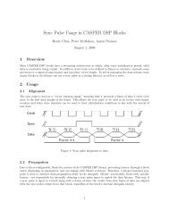
Fig. 1 shows the system level architecture of BEEm<strong>for</strong>mer. 1 <strong>BEE2</strong> supports 32 antennas single<br />
polarization data from 8 iBOBs of the ATA IF processor. It can process 3 beams with support<br />
<strong>for</strong> additional beams by cascading. As shown in the figure the total input data rate per <strong>BEE2</strong> is<br />
6.4Gbps*8+3*3.2Gbps=60.8Gbps.<br />
2.2.1 Communication between boards<br />
Beam<strong>for</strong>mers are very un<strong>for</strong>giving of any data sample slips or undetermined timing variations<br />
in clocks or communication links. Any non-determinable delay could correspond to a π radian<br />
phase shift and cause destructive phasing, thereby severely damaging the system per<strong>for</strong>mance<br />
at that frequency. To ensure predictability, usually beam<strong>for</strong>mers are designed with globally<br />
synchronous approaches with maser locked clock trees going to every board in the system. We<br />
however have tried to use a globally asynchronous but locally synchronous design paradigm, to<br />
allow <strong>for</strong> greater scaling. The iBOBs and iADC based IF processor are fed by a tree of maser<br />
locked clocks to make sure all samplers are frequency locked. The sampled and down-converted<br />
data are communicated to the BEEm<strong>for</strong>mer over asynchronous serial links and the <strong>BEE2</strong> boards<br />
2
Ant 1<br />
Ant 2<br />
Ant 3<br />
Ant 4<br />
ADC<br />
ADC<br />
iBOB<br />
iBOB<br />
ADC<br />
ADC<br />
Ant 9<br />
Ant 10<br />
Ant 11<br />
Ant 12<br />
Ant 5<br />
Ant 6<br />
Ant 7<br />
Ant 8<br />
ADC<br />
ADC<br />
iBOB<br />
iBOB<br />
ADC<br />
ADC<br />
Ant 13<br />
Ant 14<br />
Ant 15<br />
Ant 16<br />
Each iBOB per<strong>for</strong>ms<br />
Digital Down Conversion<br />
and Band Pass Filtering<br />
To Next <strong>BEE2</strong><br />
<strong>BEE2</strong><br />
From Previous <strong>BEE2</strong><br />
Ant 17<br />
Ant 18<br />
Ant 19<br />
Ant 20<br />
ADC<br />
ADC<br />
iBOB<br />
16 bits Real<br />
16 bits Imaginary<br />
at Avg: 100MHz<br />
=32Gbps<br />
iBOB<br />
ADC<br />
ADC<br />
Ant 25<br />
Ant 26<br />
Ant 27<br />
Ant 28<br />
Ant 21<br />
Ant 22<br />
Ant 23<br />
Ant 24<br />
ADC<br />
ADC<br />
iBOB<br />
Each Link<br />
4 <strong>Antenna</strong>s<br />
8 bits Real<br />
8 bits Imaginary<br />
Total 16x4=64bits at<br />
100Mhz=6.4Gbps<br />
iBOB<br />
ADC<br />
ADC<br />
Ant 29<br />
Ant 30<br />
Ant 31<br />
Ant 32<br />
Figure 1: System level architecture.<br />
3
Next board 3<br />
Next board 2<br />
Ant 9 to 16<br />
Prev board 2<br />
FPGA 2 FPGA 1<br />
Ant 1 to 8<br />
Prev board 1<br />
Ant 17 to 24 Ant 25 to 32<br />
FPGA 3<br />
FPGA 4<br />
Prev board 3<br />
Prev board 4<br />
Next board 4<br />
Next board 1<br />
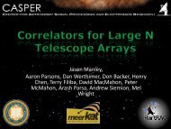
Figure 2: Board Level Architecture: Every FPGA plays the role of START <strong>for</strong> one beam, END<br />
<strong>for</strong> one beam and MID <strong>for</strong> the third beam.<br />
derive their clock from local crystal oscillators. If data transmit and recieve rates on the serial<br />
links are the same, any frequency offsets between the maser and crystal can cause the XAUI<br />
FIFOs to overflow temporarily destroying the sample number and time continuity. To avoid<br />
this scenario we run the <strong>BEE2</strong> boards much faster than they need to. The <strong>BEE2</strong> boards are<br />
fed a 200MHz clock from the crystal as opposed to the iBOB transmit rate of 100MHz, which<br />
ensures that any frequency drifts do not overflow the link FIFOs. The signal processing chain is<br />
designed to work with data bursts rather than a continuous stream to accommodate this unique<br />
architecture.<br />
2.3 Board Level Architecture<br />
Fig. 2 shows the design at the board level. Each FPGA plays the role of the first FPGA of 1 beam<br />
(START), the last FPGA of another beam (END) and an intermediate FPGA of a third beam<br />
(MID). For all 3 beams each FPGA processes 8 antennas, it receives 16 bits per sample (8 real,<br />
8 imaginary) <strong>for</strong> 4 antennas per XAUI link from 2 links coming from 2 different iBOBs. It sums<br />
up these 8 antennas via programmable delay lines to get a 32 bit sum (16 real, 16 imaginary) the<br />
4
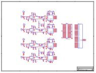
Figure 3: Chip Level Architecture: The orange blocks are replicated three times.<br />
additional bits are kept to allow upto 256 antennas in the array. In addition to these 8 antennas<br />
the beam START gets a 32 bit sum (16 Re, 16 Im) from the previous <strong>BEE2</strong> in the daisy chain<br />
over a XAUI link. MID and END use another 32 bit sum from the previous FPGA on the<br />
same board over inter-chip links. END outputs its final sum to the next <strong>BEE2</strong> in the chain over<br />
XAUI. START and MID relay their final sums to the next FPGA over inter-chip links. This<br />
architecture is used because it makes optimal use of the 4 XAUI links per FPGA available on<br />
the <strong>BEE2</strong>. 2 XAUIs are used to get data from iBOBs, 1 <strong>for</strong> getting data from previous <strong>BEE2</strong><br />
and 1 <strong>for</strong> sending data to next <strong>BEE2</strong>. Every board handles 3 simultaneous beams so START<br />
and END of 3 beams are spread across to 3 separate FPGAs.<br />
2.4 Chip Level Architecture<br />
Fig. 3 shows the BEEm<strong>for</strong>mer architecture at the level of 1 FPGA. The orange blocks are<br />
replicated thrice. The delay line consists of a FIFO based coarse delay and an FIR based fine<br />
interpolation delay. The FIR filter has demand loading of coefficients to allow delay tracking as<br />
shown in Fig.4.<br />
5
SHIFT REGISTER<br />
BRAM<br />
UPDATE<br />
C1 C2 C3 C4<br />
Delay FIFO<br />
X X X X<br />
+ +<br />
+<br />
Figure 4: Delay Architecture: 4 tap FIR filter with demand loading of coefficients and double<br />
buffering to allow smooth changes.<br />
6
2.5 BEEm<strong>for</strong>mer Status<br />
An initial prototype of BEEm<strong>for</strong>mer was designed by us this semester, it is currently being<br />
finalized by ATA engineers and scheduled <strong>for</strong> testing and deployment in late June 2007.<br />
3 <strong>DSP</strong> Processor based Beam<strong>for</strong>mer<br />
FPGA chips provide a good plat<strong>for</strong>m <strong>for</strong> designing beam <strong>for</strong>mers, but incur a high development<br />
cost. Development time could be lowered by using a microprocessor and programming the<br />
algorithm in a software language. In order to provide good per<strong>for</strong>mance, it is necessary to use<br />
an architecture that can sustain the output both in processing and in I/O bandwidth without<br />
being too costly.<br />
3.1 <strong>DSP</strong> Chip<br />
We have analyzed how the TMS320C6455, a fixed point <strong>DSP</strong> chip developed by Texas Instruments,<br />
can be used to build a beam <strong>for</strong>mer similar to the one that is described in Section 2. This<br />
processor provides a dual data path very long instruction word (VLIW) architecture. Each data<br />
path has 32 registers and four functional units. Two of the functional units execute logical, arithmetic,<br />
and branching instructions, one is used <strong>for</strong> accessing memory like loads and stores, and<br />
the last functional unit is dedicated to multiply-accumulate operations (MACs). Each multiplyaccumulate<br />
unit is capable of per<strong>for</strong>ming four 8 bit by 8 bit multiply and accumulate operations<br />
per cycle. The chip can operate at 1GHz, af<strong>for</strong>ding 8 MACs each nanosecond.<br />
The architecture provides many channels <strong>for</strong> I/O. The memory interface can move 64 bits of<br />
data at 133MHz, giving a data rate of over 8 Gbps. Interchip communication is supported with<br />
separate I/O links that run at 3.125 Gbps, full-duplex. Four of these are provided on each chip<br />
giving a communication bandwidth of over 12 Gbps.<br />
3.2 <strong>DSP</strong> Design<br />
In order to compare the plat<strong>for</strong>ms, it is necessary to see how many antennas a single <strong>DSP</strong> can<br />
process. This analysis describes what can be done on a single datapath, in order to minimize<br />
the amount of data that needs to be moved between the two register files. We explored what it<br />
would take to implement a system with single polarization 100MHz inputs and real FIR filters<br />
(with 6 taps and 8 bit data) to <strong>for</strong>m a single beam using the TMS320C6455.<br />
Approaching the design in a similar way as the FPGA architecture, many antennas could be<br />
processed in parallel. The whole sample delay is implemented by addressing memory with an<br />
offset. To interpolate between samples, the FIR filter is implemented in software. This approach<br />
is limited by the number of registers available in the datapath. Each antenna requires 12 registers<br />
total <strong>for</strong> storing the 6 FIR coefficients as well as the 6 partial sums from each FIR. Accounting<br />
<strong>for</strong> additional looping data, such as loop counters and data pointers, results in a maximum of<br />
24 registers that can be dedicated to FIR in<strong>for</strong>mation, or a maximum of 2 antennas that can be<br />
processed in parallel.<br />
Each antenna will require 6 MACs to be per<strong>for</strong>med each time a new sample comes in. A new<br />
sample is produced every 10ns. With this algorithm 12 MACs will be per<strong>for</strong>med every 10 ns<br />
while the datapath is capeable of supporting 10ns * 4 MACs/ns = 40MACs. Most of the cycles<br />
will be wasted waiting <strong>for</strong> the next value to be produced and the MAC units will only be used<br />
at 30% utilization.<br />
7
Queue 1000 samples <strong>for</strong> antenna 1<br />
Queue 1000 samples <strong>for</strong> antenna 2<br />
Queue 1000 samples <strong>for</strong> antenna 3<br />
Queue 1000 samples <strong>for</strong> antenna 4<br />
Process queued data<br />
Ant 1 Ant 2 Ant 3 Ant 4<br />
0ns<br />
1000ns<br />
Time<br />
2000ns<br />
Figure 5: Time multiplexing 4 antennas on 1 datapath<br />
<strong>for</strong>(i=0; i
To minimize additional cycles spent on adding, we will utilize the multiply accumulate from<br />
the beginning of the FIR. Referring to the loop in figure 6, calculating output[i+5] requires a<br />
multiply but no add. At this point the result from a previous antenna could be added to fully<br />
utilize the multiply accumulate. Moving the partial sums between the chips will make use of the<br />
interchip communication paths. Each chip will produce a 16 bit sample every 2 ns that needs<br />
to be transferred to an adjacent chip. This communication only requires 8 Gbps, which is much<br />
less than what is af<strong>for</strong>ded by the on chip communication.<br />
From this, it is clear that the system will be I/O limited. In the 2 ns it takes to load the<br />
data, only 6 out of a possible 8 multiplies will be calculated. This algorithm has significantly<br />
improved over the naive alternative since makes 75% utilization of the multipliers.<br />
To process 1,000 samples of data it will take 2,000 ns plus additional latency to switch between<br />
antennas. When switching between antennas, it is necessary to load the new FIR coefficients<br />
and begin preloading the cache. In 10,000 ns, at most 4 antennas can be processed on a data<br />
path. Overall, the entire chip can process the real part of 8 antennas. To do the entire complex<br />
calculation, 2 chips are necessary <strong>for</strong> processing 8 antennas.<br />
4 Conclusions<br />
We have successfully demonstrated the suitability of the <strong>BEE2</strong> plat<strong>for</strong>m <strong>for</strong> building highly<br />
scalable antenna array beam <strong>for</strong>mers. In addition our comparison with <strong>DSP</strong> processors has shown<br />
us that though correlators map very well to FPGAs alone, beam <strong>for</strong>mers can have alternative<br />
and equally viable <strong>DSP</strong> processor implementations.<br />
References<br />
[1] TMS320C6455 fixed-point digital signal processor. Technical report, Texas Instruments, 2007.<br />
[2] Chen Chang, John Wawrzynek, and Robert W. Brodersen. <strong>BEE2</strong>: A high-end reconfigurable<br />
computing system. IEEE Design and Test, 22(2), 2005.<br />
[3] R. D’Addario. ATA memo 27: Notes on delay and phase tracking <strong>for</strong> the ATA. Technical<br />
report, Radio Astronomy Labs, UC Berkeley, 2001.<br />
[4] R. D’Addario. ATA memo 43: Digital processing architecture of the ATA. Technical report,<br />
Radio Astronomy Labs, UC Berkeley, 2002.<br />
[5] G.R. Harp. ATA memo 51: Customized beam <strong>for</strong>ming at the allen telescope array. Technical<br />
report, Radio Astronomy Labs, UC Berkeley, 2002.<br />
[6] Vinayak Nagpal. An FPGA based phased array processor <strong>for</strong> the sub-millimeter array, 2006.<br />
[7] Aaron Parsons, Donald Backer, Chen Chang, Daniel Chapman, Henry Chen, Patrick Crescini,<br />
Christina de Jesus, Chris Dick, Pierre Droz, David MacMahon, Kirsten Meder, Jeff Mock,<br />
Vinayak Nagpal, Borivoje Nikolic, Arash Parsa, Brian Richards, Andrew Siemion, John<br />
Wawrzynek, Dan Werthimer, and Melvyn Wright. Petaop/second FPGA signal processing<br />
<strong>for</strong> SETI and radio astronomy. Proceedings of the Asilomar Conference on Signals, Systems,<br />
and Computers., 2006.<br />
[8] M.C.H. Wright. ATA memo 1: Astronomical imaging with the one hectare telescope. Technical<br />
report, Radio Astronomy Labs, UC Berkeley, 1998.<br />
9