SR-30 Small Turbojet Engine Laboratory - Turbine Technologies
SR-30 Small Turbojet Engine Laboratory - Turbine Technologies SR-30 Small Turbojet Engine Laboratory - Turbine Technologies
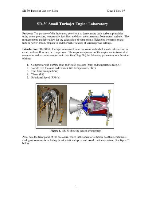
SR-30 Turbojet Lab ver 4.doc Due: 1 Nov 07 SR-30 Small Turbojet Engine Laboratory Purpose: The purpose of this laboratory exercise is to demonstrate basic turbojet principles using actual pressure, temperature, fuel flow and thrust measurements from a small turbojet. The measurements available allow for the calculation of component efficiencies, compressor and turbine power, thrust, propulsive and thermal efficiency at various power settings. Introduction: The SR-30 Turbojet is mounted in an enclosure with a bell mouth inlet section to create uniform flow into the compressor. The major components of the engine are instrumented to measure and record to an electronic data file (*.log file) the following parameters as a function of time: 1. Compressor and Turbine Inlet and Outlet pressure (psig) and temperature (deg. C) 2. Nozzle Exit Pressure and Exhaust Gas Temperature (EGT) 3. Fuel flow rate (gal/hour) 4. Thrust (lbf) 5. Rotational Speed (RPM’s) Figure 1. SR-30 showing sensor arrangement Also, note the front panel of the enclosure, which is the operator’s station, has three continuous analog measurements including thrust, rotational speed and nozzle exit temperature. See figure 2 below. 1
- Page 2 and 3: SR-30 Turbojet Lab ver 4.doc Due: 1
- Page 4: SR-30 Turbojet Lab ver 4.doc Due: 1
<strong>SR</strong>-<strong>30</strong> <strong>Turbojet</strong> Lab ver 4.doc Due: 1 Nov 07<br />
<strong>SR</strong>-<strong>30</strong> <strong>Small</strong> <strong>Turbojet</strong> <strong>Engine</strong> <strong>Laboratory</strong><br />
Purpose: The purpose of this laboratory exercise is to demonstrate basic turbojet principles<br />
using actual pressure, temperature, fuel flow and thrust measurements from a small turbojet. The<br />
measurements available allow for the calculation of component efficiencies, compressor and<br />
turbine power, thrust, propulsive and thermal efficiency at various power settings.<br />
Introduction: The <strong>SR</strong>-<strong>30</strong> <strong>Turbojet</strong> is mounted in an enclosure with a bell mouth inlet section to<br />
create uniform flow into the compressor. The major components of the engine are instrumented<br />
to measure and record to an electronic data file (*.log file) the following parameters as a function<br />
of time:<br />
1. Compressor and <strong>Turbine</strong> Inlet and Outlet pressure (psig) and temperature (deg. C)<br />
2. Nozzle Exit Pressure and Exhaust Gas Temperature (EGT)<br />
3. Fuel flow rate (gal/hour)<br />
4. Thrust (lbf)<br />
5. Rotational Speed (RPM’s)<br />
Figure 1. <strong>SR</strong>-<strong>30</strong> showing sensor arrangement<br />
Also, note the front panel of the enclosure, which is the operator’s station, has three continuous<br />
analog measurements including thrust, rotational speed and nozzle exit temperature. See figure 2<br />
below.<br />
1
<strong>SR</strong>-<strong>30</strong> <strong>Turbojet</strong> Lab ver 4.doc Due: 1 Nov 07<br />
Figure 2. <strong>SR</strong>-<strong>30</strong> front panel and data acquisition system<br />
The data acquisition system is provided using a PC and software allowing continuous display of<br />
measurements from the <strong>SR</strong>-<strong>30</strong> as well as a data logging feature, placing parameters in a flat file<br />
such as “filename.log”. This file is easily imported to Microsoft Excel or Matlab for later<br />
analysis of the data. The data-acquisition software operation is relatively simple and will be<br />
reviewed at the beginning of the lab.<br />
Safety: During operations of the <strong>SR</strong>-<strong>30</strong> all personnel are required to wear hearing protection and<br />
skylarking is strictly forbidden. The faculty and <strong>SR</strong>-<strong>30</strong> operator will provide further system<br />
safety guidance as required. Some other safety issues are enumerated below from<br />
http://kahuna.sdsu.edu/~bjones<br />
WARNING<br />
Make sure that neither you nor any of your belongings are placed in front of the intake or<br />
the exhaust sections of the <strong>SR</strong>-<strong>30</strong> engine while it is operating.<br />
Ear protection must be worn while the <strong>SR</strong>-<strong>30</strong> engine is operating.<br />
The <strong>SR</strong>-<strong>30</strong> engine rotates at very high speeds. Stay as far from the test bench as practical<br />
to avoid injury if the engine malfunctions.<br />
<br />
Make sure the engine low-oil-pressure light extinguishes immediately after engine startup.<br />
If the light stays illuminated or lights at any time during engine operation turn off the<br />
fuel flow to the <strong>SR</strong>-<strong>30</strong> engine immediately.<br />
Observe the vibration sensor indicator on the far right side of the control panel. If the<br />
indicator voltage increases at any time during engine operation turn off the fuel flow to<br />
the <strong>SR</strong>-<strong>30</strong> engine immediately.<br />
If at any time you suspect the <strong>SR</strong>-<strong>30</strong> engine is not operating properly immediately turn off<br />
the fuel flow and shut down the engine.<br />
Upon engine start, if the engine starts but does not increase to idle speed (40,000 rpm)<br />
turn the air start back on until the engine reaches <strong>30</strong>,000 rpm. Then turn the air-start off.<br />
2
<strong>SR</strong>-<strong>30</strong> <strong>Turbojet</strong> Lab ver 4.doc Due: 1 Nov 07<br />
Procedure: The sequence of events for the <strong>SR</strong>-<strong>30</strong> laboratory are as follows:<br />
1. Prior to start-up of the engine students will review the data acquisition software<br />
operations, obtain hearing protection and record start of lab ambient conditions. The data<br />
acquisition mode should be “fast” and data-logging should be “on”. Also any physical<br />
measurements should be made at this time – atmospheric conditions, nozzle/inlet<br />
geometry.<br />
2. The operator will start the <strong>SR</strong>-<strong>30</strong> and allow it to remain at idle RPM (about 48,000) while<br />
the components warm up to a steady state conditions (about 5 minutes). Students should<br />
record the analog readings from the operators console after the system reaches steady<br />
state. Trends can be observed by watching the traces in the data acquisition software<br />
window.<br />
Figure 3. Sample data acquisition screen showing data traces/trends<br />
3. This procedure will be repeated for 60,000, 70,000 and 80,000 RPM as well as full<br />
throttle (about 86,600 RPM) allowing time for temperatures to come to a quasi-steady<br />
state value. The engine will then be returned to an idle throttle setting for one final set of<br />
readings and shut down.<br />
4. The *.log file must be extracted onto disk or flash memory for later use.<br />
All figures obtained from: http://bookitec.co.kr/avionics.htm<br />
Purpose: The purpose of this laboratory is to examine the performance of <strong>SR</strong>-<strong>30</strong> <strong>Turbojet</strong>.<br />
From this exercise, you should be able to evaluate important component parameters that<br />
contribute to the performance of the turbojet system. This exercise will combine analysis of <strong>SR</strong>-<br />
<strong>30</strong> data with the use of GASTURB10.<br />
Results: Work on this laboratory in groups of two (2) to complete the calculations listed below.<br />
Sample calculations should be provided for at least one power setting, which will serve to<br />
indicate your calculation procedure and assumptions. Do the calculations by hand and summarize<br />
in tables and plots I can read!<br />
1. Estimate of turbine inlet temperature if required. Describe the process used to make this<br />
estimate. You should assume variable gas properties for all calculations (c p , and R gas )<br />
3
<strong>SR</strong>-<strong>30</strong> <strong>Turbojet</strong> Lab ver 4.doc Due: 1 Nov 07<br />
2. Compressor and turbine work rate (hp and kW) and estimate of mechanical efficiency<br />
3. Compressor and turbine efficiencies<br />
4. Estimate engine mass flow rate (lb/sec, kg/sec)<br />
5. Estimate engine exit velocity (ft/sec, m/sec) – what is the inlet velocity Can you<br />
estimate it<br />
6. Describe the state of the nozzle; converging only, choked, not choked. What is the exit<br />
Mach number Please make sure you get the proper dimensions for the nozzle and inlet.<br />
7. Estimate thrust using the thermodynamic data and relationships from Chapter 5 of our<br />
class handout and compare to measured values (lbf, N)<br />
8. Determine TSFC (lbm/lbf-hr, kg/N-hr)<br />
9. <strong>SR</strong>-<strong>30</strong> thermal efficiency. What is the propulsive efficiency Can it be determined<br />
Discussion questions: Answer the following discussion questions to form the basis for your<br />
discussion and conclusions.<br />
1. In order to complete the above calculations you had to make some assumptions. Please<br />
comment on these and any other workarounds required to determine engine parameters.<br />
2. The <strong>SR</strong>-<strong>30</strong> operated at various power settings during this lab. Did <strong>SR</strong>-<strong>30</strong> operate at the<br />
maximum power or efficiency condition(s) during this lab (look at pressure ratio) or<br />
something else What is the maximum thrust pressure ratio ( c *) and what would the<br />
net thrust, TSFC and thermal efficiency of <strong>SR</strong>-<strong>30</strong> be at maximum thrust pressure ratio<br />
3. Plot experimental values of c , thrust and thermal efficiency versus RPM Describe the<br />
relationship between these three and RPM.<br />
4. How would you characterize the <strong>SR</strong>-<strong>30</strong> in terms of performance How would you<br />
describe this engine to someone who was looking at it for a real application<br />
Now using GASTURB10 do the following:<br />
5. Plot specific thrust, TSFC and core efficiency as function of c using the T max /T min ratio<br />
for 80,000 RPMs. Do this for three flight Mach numbers on a single plot and then<br />
another Thrust/TSFC versus c plot with three different altitudes. Make selections that<br />
indicate the variation with Mach number and altitude.<br />
6. Create a turbojet map for the <strong>SR</strong>-<strong>30</strong> by plotting TSFC (lb/lbf-hr) versus Specific Thrust<br />
(lbf-sec/lb) between pressure ratios of 2-3 and turbine inlet temperatures of 900K to<br />
1050K. This will be a contour map of c and T t4 . Adjust values to create a meaningful<br />
map.<br />
Deliverables: Perform all the tasks above in a very professional manner. Please note this is not a<br />
formal laboratory write-up, but an informal format might be a good compromise. I do not need a<br />
description of the set-up or any long-winded description of the importance of turbojets to the<br />
Navy or the universe at large. Just a description of what you did, how you did it and a clear<br />
demonstration that you understand turbojet calculations!<br />
4


