470 Mast Deflection Procedure - North Sails - One Design
470 Mast Deflection Procedure - North Sails - One Design
470 Mast Deflection Procedure - North Sails - One Design

You also want an ePaper? Increase the reach of your titles
YUMPU automatically turns print PDFs into web optimized ePapers that Google loves.
<strong>470</strong> <strong>Mast</strong> <strong>Deflection</strong> <strong>Procedure</strong><br />
Overview<br />
There are multiple methods for deflecting a given mast. At <strong>North</strong> <strong>Sails</strong> <strong>One</strong> <strong>Design</strong>, we believe the<br />
following procedure will best indicate the bend properties of your masts (stiff or soft; where is the bend<br />
concentrated, etc.). <strong>Mast</strong> deflection procedures often vary from sailor to sailor. It is important to dedicate<br />
the time and tools needed for a proper mast deflection. Otherwise, the data may be compromised. It is<br />
also critical to follow the steps in order and deflect each of your masts with the same exact procedure. As<br />
you continue to deflect masts, your ability to run through the procedure will become more efficient;<br />
however, skipping or rushing steps will affect your data. Keep in mind that the data requires concentration<br />
to the millimeter, so improper procedure can nullify your data set.<br />
Components/Tools<br />
1) Reliable, easy-to-see string. We recommend using Marlow 4oz Whipping Twine or a similar<br />
product. Most sailors have whipping twine in their toolbox, so it is often easy to secure. The line<br />
is easy to see and does not break under load.<br />
2) A 0.5Kg weight (or weight in similar range. 1lbs will do)<br />
3) 15Kg weight (33.07lbs)<br />
4) Short piece of line to attach the 15Kg weight to the mast. This can include a hook to make the<br />
procedure easier. Please subtract the weight of the line and hook from the 15Kg max.<br />
5) 2x sawhorses, or stable platform with similar height.<br />
6) 2x angled edges (such as a piece of angled aluminum extrusion or piece of wood).<br />
7) 2x large C-clamps (to secure the mast butt to the saw horse, if need be)<br />
8) Metric ruler (30cm).<br />
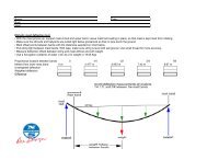
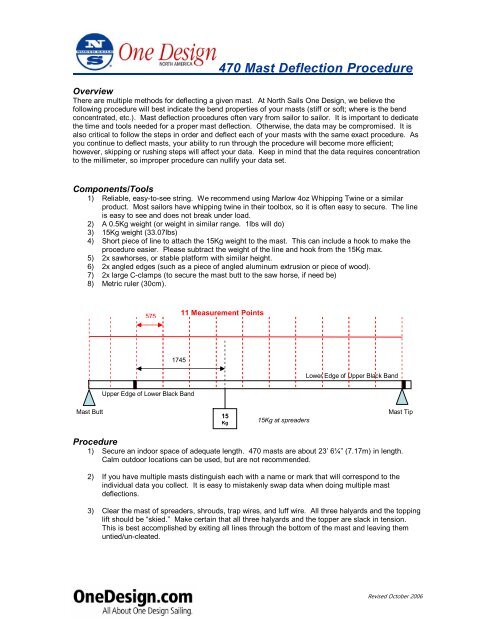
575<br />
11 Measurement Points<br />
1745<br />
Lower Edge of Upper Black Band<br />
Upper Edge of Lower Black Band<br />
<strong>Mast</strong> Butt<br />
15<br />
Kg<br />
15Kg at spreaders<br />
<strong>Mast</strong> Tip<br />
<strong>Procedure</strong><br />
1) Secure an indoor space of adequate length. <strong>470</strong> masts are about 23’ 6¼” (7.17m) in length.<br />
Calm outdoor locations can be used, but are not recommended.<br />
2) If you have multiple masts distinguish each with a name or mark that will correspond to the<br />
individual data you collect. It is easy to mistakenly swap data when doing multiple mast<br />
deflections.<br />
3) Clear the mast of spreaders, shrouds, trap wires, and luff wire. All three halyards and the topping<br />
lift should be “skied.” Make certain that all three halyards and the topper are slack in tension.<br />
This is best accomplished by exiting all lines through the bottom of the mast and leaving them<br />
untied/un-cleated.<br />
Revised October 2006
<strong>470</strong> <strong>Mast</strong> <strong>Deflection</strong> <strong>Procedure</strong><br />
4) With the track facing up, lay the mast horizontally such that the tip and butt rest on the saw<br />
horses (or other mounts of equal height). Total height needs to be in the meter-plus range so that<br />
the deflection weights do not touch the ground when loaded on the mast. Drop the excess<br />
halyards to the ground.<br />
5) Beginning with top edge of the lower black band (measurement band) mark the mast with marker<br />
every 575mm. The top edge of the lower band is the “0”. If done correctly, the bottom edge of the<br />
upper black band should intersect one of the 575mm increments at exactly 5750mm. Continue<br />
below the “0” another 575mm and make a final mark. At this point, the mast should be divided<br />
into 12 segments (11 equal segments of 575mm and one 480mm segment).<br />
6) Place one angled aluminum (or similar piece) under the mast tip such that the point is focused on<br />
the lower edge of the black band. Place the second piece under the mast butt such that the point<br />
is focused as close to the mast butt as possible, but not on the actual mast butt key (the part that<br />
fits into the mast step). Make note of this location with a permanent marker of piece of tape.<br />
Some mast butts, such as those with SuperSpars, include odd angles and make positioning the<br />
angled aluminum difficult. Use the large C-clamp to secure the whole system.<br />
7) Secure the measurement string to the mast tip as closely to the mast track as possible.<br />
8) Run the string the length of the mast and drape over the end of the mast butt. Tie the 0.5Kg<br />
weight to the end of the string so that the weigh is suspended above the ground.<br />
9) Once tension is applied to the string via the hanging weight, rest a roll of tape (or other object) on<br />
the mast track and under the string at the lower edge of the upper black band (see Diagrams 1<br />
and 2). This will bend the string directly above the focus point made by the angled aluminum. Do<br />
the same at the mast butt focus point. Make certain to use the same width tape/object. The<br />
objective is to raise the string above the hardware of the mast so that the string runs clear tip to<br />
butt. Different masts will require different set-up attention.<br />
Diagrams 1 & 2: Use a roll of tape to support tensioned string at measurement points<br />
10) With the entire system secured, use a metric ruler to measure the distance from each marked<br />
segment (Step #5) perpendicular to the taught string above. It is important to ensure the ruler is<br />
exactly perpendicular to the line (not the mast). A second set of eyes can make this job easier.<br />
Also, a good trick is to cut off the bottom of the ruler at exactly 0mm. You can just barely rest the<br />
bottom edge of the ruler on the mast, but it is easy to accidentally add too much downward<br />
pressure and skew the measurement. Also, the mast can bounce easily. You must dampen any<br />
and all movement before each measurement. Record the data in the following table under Fore-<br />
Aft Bend (Initial). Feel free to record to the 0.5mm if the string lies between two mm points.<br />
Also, do not hesitate to measure each station twice (or have someone else measure) to allow for<br />
human error.<br />
Revised October 2006
<strong>470</strong> <strong>Mast</strong> <strong>Deflection</strong> <strong>Procedure</strong><br />
11) Secure a 15Kg weight to the spreaders. A good trick is to tie a loop that spans over the top of one<br />
spreader bracket and under the opposite spreader bracket. The goal is that the focus of the<br />
weight is centered in the middle of the brackets. Use of a hook to quickly fashion the weigh to the<br />
loop is handy, just make sure to subtract the weight of the hook and line from the overall 15Kg<br />
weight. If using Imperial weights, two 15lbs, one 3lbs, and a spare block is about equal to 15Kg.<br />
Of course, weight the system with a scale first.<br />
12) Measure each station as done in Step #10. Record under Fore-Aft Bend (Measured).<br />
13) Take off the weight and rotate mast and systems such that the mast is secured on its side with<br />
the Starboard side facing up. Remove the objects that held up the string as described in Step #9.<br />
Some masts are difficult to position on the sides, particularly when weight is attached. Make<br />
certain your clamping system fixes the butt of the mast perpendicular to the ground.<br />
14) At this point, the string should still be taught with the 0.5 Kg weight. Tape over the string at the<br />
top black band and at the mast butt in order to secure both end points. If any mast gear<br />
(gooseneck) still interferes with the string, you will need to raise the strip above the mast track,<br />
but not away from the mast track (as that will complicate measurements).<br />
15) Measure each station as done in Step #10. Record as Side Bend S (Initial).<br />
16) Affix the 15Kg weight and repeat measurements. Again, make certain that the mast does not<br />
twist from perpendicular. Record as Side Bend S (Measured).<br />
17) Rotate mast and systems so that the Port side is facing up. Repeat Steps #14-16. Record under<br />
Side Bend P (Initial) and Side Bend P (Measured).<br />
18) Subtract all “Initial” measurements from “Measured” measurements to complete the data set for<br />
Fore-Aft Bend (Corrected), Side Bend S (Measured), and Side Bend P (Measured). Please<br />
refer to the <strong>Mast</strong> <strong>Deflection</strong> Form.<br />
Additional Tips<br />
1) Different mast manufacturers use different components. Some ingenuity may be needed when<br />
securing the systems. It is best, of course, to use the same tools with each deflection (saw<br />
horses, etc.).<br />
2) Use of a mast deflection jig can be useful. The jig essentially holds the mast top and butt in place<br />
and allows for a riser for the string to set on. The jigs are then clamped to the saw horses. Use<br />
of a jig can also limit the torque from the mast when measuring the side-to-side deflection.<br />
3) If need be, you may choose to only measure one side deflection.<br />
Data Review & Additional Information<br />
Use the <strong>North</strong> <strong>Sails</strong> <strong>One</strong> <strong>Design</strong> <strong>Mast</strong> <strong>Deflection</strong> Form to collect your data. Please note that “Initial” refers<br />
the measurements when the mast is at rest (with no weight at the spreaders) and “Measured” referrers to<br />
when the 15Kg weight is applied. The “Corrected” data is the delta of the two, as stated in Step #18. It is<br />
the “Corrected” data that will be used to determine the overall characteristics of your mast; however, the<br />
“Initial” data can be used for further analysis of the mast column.<br />
<strong>North</strong> <strong>Sails</strong> <strong>One</strong> <strong>Design</strong> is happy to review and plot the collected data. We will review the accuracy of the<br />
test and graph the bend characteristics of your mast. Your data will not be shared. Please contact Dave<br />
Hughes at 619-226-1415 and dave@od.northsails.com – or any <strong>North</strong> <strong>Sails</strong> <strong>One</strong> <strong>Design</strong> representative –<br />
for more information.<br />
Revised October 2006
Owner<br />
Date of <strong>Deflection</strong><br />
Location of <strong>Deflection</strong><br />
<strong>Mast</strong> Type<br />
<strong>Mast</strong> Model<br />
<strong>Mast</strong> Date/Age<br />
<strong>Mast</strong> Name Reference<br />
Notes<br />
<strong>470</strong> <strong>Mast</strong> <strong>Deflection</strong> Form<br />
Distance from<br />
Lower Black Band<br />
Fore-Aft Bend<br />
(Initial)<br />
Fore-Aft Bend<br />
(Measured)<br />
Fore-Aft Bend<br />
(Corrected)<br />
-1055 mm 0 0 0<br />
-575 mm<br />
0 mm<br />
575 mm<br />
1150 mm<br />
1725 mm<br />
2300 mm<br />
2875 mm<br />
3450 mm<br />
4025 mm<br />
4600 mm<br />
5175 mm<br />
5750 mm 0 0 0<br />
Distance from Lower<br />
Black Band<br />
Side Bend S<br />
(Initial)<br />
Side Bend S<br />
(Measured)<br />
Side Bend S<br />
(Corrected)<br />
Side Bend P<br />
(Initial)<br />
Side Bend P<br />
(Measured)<br />
Side Bend P<br />
(Corrected)<br />
-1055 mm 0 0 0 0 0 0<br />
-575 mm<br />
0 mm<br />
575 mm<br />
1150 mm<br />
1725 mm<br />
2300 mm<br />
2875 mm<br />
3450 mm<br />
4025 mm<br />
4600 mm<br />
5175 mm<br />
5750 mm 0 0 0 0 0 0<br />
Revised October 2006