lit-32686 rev_a d8000 and d4200 remote ir stations.qxp - Leviton
lit-32686 rev_a d8000 and d4200 remote ir stations.qxp - Leviton
lit-32686 rev_a d8000 and d4200 remote ir stations.qxp - Leviton

Create successful ePaper yourself
Turn your PDF publications into a flip-book with our unique Google optimized e-Paper software.
FULL<br />
BRIGHT<br />
PHASE LOSS<br />
FULL BRIGHT<br />
FAN<br />
SELECT<br />
SAVE<br />
COMMUNICATION PORTS<br />
AUXILIARY<br />
DMX<br />
CANCEL<br />
LUMANET<br />
CLEAR<br />
A<br />
B<br />
C<br />
1<br />
2<br />
3<br />
4<br />
5<br />
6<br />
7<br />
8<br />
9<br />
10<br />
11<br />
12<br />
13<br />
14<br />
15<br />
16<br />
17<br />
18<br />
PHASE LOSS<br />
FULL BRIGHT<br />
FAN<br />
COMMUNICATION PORTS<br />
AUXILIARY<br />
DMX<br />
LUMANET<br />
A<br />
B<br />
C<br />
1<br />
2<br />
3<br />
4<br />
5<br />
6<br />
7<br />
8<br />
9<br />
10<br />
11<br />
12<br />
13<br />
14<br />
15<br />
16<br />
17<br />
18<br />
FULL<br />
BRIGHT<br />
SELECT<br />
SAVE<br />
CANCEL<br />
CLEAR<br />
1<br />
2<br />
3<br />
4<br />
5<br />
6<br />
Limited Warranty<br />
Warnings<br />
Introduction<br />
LEVITON LIGHTING CONTROL DIVISION of<br />
<strong>Leviton</strong> Manufacturing Co Inc. warrants its Dimmer<br />
Systems <strong>and</strong> Controls to be free of material <strong>and</strong> workmanship<br />
defects for a period of two years after system<br />
acceptance or 26 months after shipment, whichever<br />
comes f<strong>ir</strong>st. This Warranty is limited to repa<strong>ir</strong> or replacement<br />
of defective equipment returned Freight Pre-Paid to<br />
<strong>Leviton</strong> Lighting Control Division at 20497 SW Teton<br />
Ave., Tualatin, Oregon 97062, USA. User shall call 1-<br />
800-959-6004 <strong>and</strong> request a return authorization number<br />
to mark on the outside of the returning carton, to assure<br />
that the returned material will be properly received at<br />
<strong>Leviton</strong>. All equipment shipped back to <strong>Leviton</strong> must be<br />
carefully <strong>and</strong> properly packed to avoid shipping damage.<br />
Replacements or repa<strong>ir</strong>ed equipment will be returned to<br />
sender freight prepaid, F.O.B. factory. <strong>Leviton</strong> is not<br />
responsible for removing or replacing equipment on the<br />
job site, <strong>and</strong> will not honor charges for such work.<br />
<strong>Leviton</strong> will not be responsible for any loss of use time or<br />
subsequent damages should any of the equipment fail<br />
during the warranty period, but agrees only to repa<strong>ir</strong> or<br />
replace defective equipment returned to its plant in<br />
Tualatin, Oregon. This Warranty is void on any product<br />
that has been improperly installed, overloaded, short c<strong>ir</strong>cuited,<br />
abused, or altered in any manner. Neither the<br />
seller nor <strong>Leviton</strong> shall be liable for any injury, loss or<br />
damage, d<strong>ir</strong>ect or consequential arising out of the use of<br />
or inabi<strong>lit</strong>y to use the equipment. This Warranty does not<br />
cover lamps, ballasts, <strong>and</strong> other equipment which is supplied<br />
or warrantied d<strong>ir</strong>ectly to the user by the<strong>ir</strong> manufacturer.<br />
<strong>Leviton</strong> makes no warranty as to the Fitness for<br />
Purpose or other implied Warranties.<br />
Ceiling Mount IR for<br />
D4200 <strong>and</strong> D8000<br />
Cat # D42IR-RSW<br />
D42IR-RFW<br />
KIRRF-00W<br />
KIRRS-00W<br />
1. To be installed <strong>and</strong>/or used in accordance with<br />
appropriate electrical codes <strong>and</strong> regulations.<br />
2. To be installed by a qualified Electrician.<br />
3. DO NOT CONNECT line voltage w<strong>ir</strong>es to low voltage<br />
terminals.<br />
4. For the best lamp life, lamp manufacturers recommend<br />
the<strong>ir</strong> fluorescent lamps should be operated at<br />
full brightness for a minimum of 100 hours before dimming<br />
is permitted. For best results, lamp br<strong>and</strong>s <strong>and</strong><br />
types should not be intermixed on a c<strong>ir</strong>cuit.<br />
5. Disconnect power when servicing the dimmer, fixture<br />
or when changing lamps.<br />
6. Indoor use only.<br />
7. TO AVOID FIRE, SHOCK OR DEATH: TURN OFF<br />
POWER AT MAIN CIRCUIT BREAKER OR FUSE<br />
AND TEST THAT THE POWER IS OFF BEFORE<br />
WIRING!<br />
For best results using the Dimensions 8000 Architectural<br />
Lighting Controller, Follow these recommendations:<br />
1. Plan the system before beginning the installation<br />
2. Terminate the w<strong>ir</strong>ing<br />
3. Test the w<strong>ir</strong>ing<br />
4. Connect dimmer cabinets<br />
5. Check Voltages<br />
6. Power up the Stations<br />
7. Program each Station<br />
Assign unique network ID numbers to <strong>stations</strong>.<br />
Check the proper operation of each station as it is<br />
installed when multiple <strong>stations</strong> are involved.<br />
8. Install all Stations<br />
Note: If the lighting control fails or becomes sporadic,<br />
f<strong>ir</strong>st check the w<strong>ir</strong>ing or network ID.<br />
For Technical Assistance Call:<br />
1-800-959-6004<br />
www.nsicorp.com<br />
www.leviton.com<br />
LIT-<strong>32686</strong>-000<br />
Rev A 3/2004<br />
1 2<br />
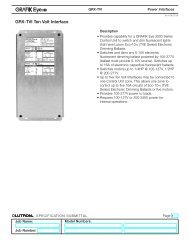
Terminating the W<strong>ir</strong>ing<br />
Luma-Net® III<br />
Control Stations can be located up to 2000 ft. from<br />
the dimming cabinet. Luma-Net® is w<strong>ir</strong>ed Daisy<br />
Chained, station to station. For applications where<br />
runs become too long, or a star configuration is<br />
des<strong>ir</strong>ed, a Hub can be used.<br />
The cable should not pass near any source of electrical<br />
noise such as fluorescent c<strong>ir</strong>cuits or motor w<strong>ir</strong>ing.<br />
Avoid close proximity to any AC w<strong>ir</strong>ing<br />
All control/power w<strong>ir</strong>ing must be in conduit.<br />
Luma-Net® W<strong>ir</strong>e Recommendations<br />
1. Use RS485 compatible cable for communications.<br />
It is recommended that a cable with 2 Twisted Pa<strong>ir</strong>,<br />
24 AWG (min.), str<strong>and</strong>ed conductors be used. The<br />
spare pa<strong>ir</strong> is for future uses.<br />
2. Capacitance of w<strong>ir</strong>e shall be 15pF/ft. or less.<br />
3. Normal Impedance of w<strong>ir</strong>e shall be between 100-<br />
120 ohms.<br />
4. Drain/Shields to be tied together, insulated <strong>and</strong><br />
grounded at one point only.<br />
We strongly recommend the use of either Belden<br />
9829, Belden 8102 or Belden 9729 for the Luma-<br />
Net® w<strong>ir</strong>e runs.<br />
5. A second pa<strong>ir</strong> of str<strong>and</strong>ed w<strong>ir</strong>e is requ<strong>ir</strong>ed for the<br />
power.<br />
PRESET SELECT STATION<br />
D4200 CONTROL STATION<br />
Note: a-2000D Cabinet can be in the<br />
middle of a daisy chain<br />
a-2000D<br />
PRESET SELECT STATION<br />
LUMA-NET III HUB<br />
D4200 CONTROL STATION<br />
D4200 CONTROL STATION<br />
PRESET SELECT STATION<br />
a-2000D<br />
a-2000D<br />
3 4<br />
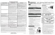
If a <strong>remote</strong> DC power supply is used <strong>and</strong> you have multiple<br />
Luma-Net® runs, all DC common w<strong>ir</strong>es must be<br />
joined at the power supply.<br />
At the last control station or dimmer cabinet on both ends<br />
of run, a small jumper w<strong>ir</strong>e must be run from the terminal<br />
labeled “Rem-” to the terminal marked “Term” on that last<br />
station. This jumper w<strong>ir</strong>e properly terminates the digital<br />
communications lines at both ends of the line.<br />
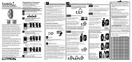
W<strong>ir</strong>e the Phoenix/Luma-Net Connector<br />
1. Connect leads per w<strong>ir</strong>ing diagram as illustrated on page<br />
6.<br />
2. Twist str<strong>and</strong>s of each lead tightly (making sure that<br />
there are no stray str<strong>and</strong>s) <strong>and</strong> push f<strong>ir</strong>mly into appropriate<br />
plug connector location.<br />
3. Tighten the screws on the plug connector-making sure<br />
that no bare conductor is showing.<br />
4. Tie the Drain/Shield w<strong>ir</strong>es together <strong>and</strong> insulate using a<br />
small piece of heat shrink tubing.<br />
5. Install termination jumpers as requ<strong>ir</strong>ed. Remember a<br />
termination jumper is requ<strong>ir</strong>ed at the two ends of the<br />
Luma-Net® run.<br />
Drain/Shield - Insulated <strong>and</strong> tied together<br />
(Ground at one point onlyprobably<br />
an end)<br />
REM+<br />
REM -<br />
COM<br />
+V<br />
TERM<br />
LOCK<br />
Up to 1 #12AWG<br />
Up to 1 #12AWG<br />
2#12AWG<br />
2 3 4 5 6<br />
Luma-Net® W<strong>ir</strong>e Connections<br />
Black (Common)<br />
2#12AWG<br />
Red (+V )<br />
5 6<br />
1<br />
Phoenix/Luma-Net Connector
1<br />
PHASE LOSS<br />
FULL BRIGHT<br />
FAN<br />
COMMUNICATION PORTS<br />
AUXILIARY<br />
DMX<br />
LUMANET<br />
A<br />
B<br />
C<br />
1<br />
2<br />
3<br />
4<br />
5<br />
6<br />
7<br />
8<br />
9<br />
10<br />
11<br />
12<br />
13<br />
14<br />
15<br />
16<br />
17<br />
18<br />
FULL<br />
BRIGHT<br />
SELECT<br />
SAVE<br />
CANCEL<br />
CLEAR<br />
D12<br />
R30<br />
C<br />
+<br />
C 2002<br />
+<br />
B E<br />
LEVITON MFG. CO.<br />
MADE IN THE U.S.A.<br />
+<br />
+<br />
PTB7<br />
PTB6<br />
ALL RIGHTS RESERVED<br />
+<br />
R27<br />
To specify a button to listen to a specific comm<strong>and</strong><br />
from a H<strong>and</strong> Held <strong>remote</strong> other than default programming:<br />
1. Open a 15 Button station in LumaEdit<br />
2. Set the Network ID for the IR station.<br />
3. Set the ID of the station it will be slaved to.<br />
4. Click on the Enable IR button in the Station<br />
Properties Section under Layout.<br />
PCA-61418-0X<br />
REV-<br />
R14<br />
R23<br />
+<br />
+<br />
TP2<br />
OSC2<br />
TP1<br />
GND<br />
D7<br />
R<br />
V<br />
C3<br />
PRESET SELECT STATION<br />
Ground Shield<br />
at one point only!<br />
D4200 CONTROL STATION<br />
Terminate LumaNet in<br />
these locations<br />
A2000-D<br />
Luma-Net® Termination Jumper<br />
Locations<br />
REM+<br />
REM -<br />
COM<br />
+V<br />
TERM<br />
LOCK<br />
2<br />
3<br />
4<br />
5<br />
6<br />
Termination Jumper<br />
1<br />
2 3 4 5 6<br />
Phoenix/Luma-Net<br />
Connector<br />
Testing the W<strong>ir</strong>ing<br />
To assure problem-free start-up, it is important to check<br />
the system w<strong>ir</strong>ing, prior to hooking up any control <strong>stations</strong>,<br />
for proper connections, shorts <strong>and</strong> opens.<br />
The following procedure is recommended:<br />
Step 1: Test the following w<strong>ir</strong>e pa<strong>ir</strong>s for shorts at each<br />
station location, using an ohmmeter or other continuity<br />
tester.<br />
1-2 Open<br />
2-3 Open<br />
3-4 Open<br />
Step 2: Repa<strong>ir</strong> any short c<strong>ir</strong>cuits before continuing.<br />
Step 3: Install w<strong>ir</strong>e jumpers, one pa<strong>ir</strong> at a time (not<br />
supplied) to the Luma-Net Connector on either end of<br />
the cable run between pins 1-2, then 2-3, then 3-4.<br />
Step4: Retest each of the following w<strong>ir</strong>e pa<strong>ir</strong>s at each<br />
connector:<br />
1-2 Short<br />
2-3 Short<br />
3-4 Short<br />
Step 5: Make any necessary repa<strong>ir</strong>s <strong>and</strong> remove w<strong>ir</strong>e<br />
jumpers before continuing.<br />
Station Addressing<br />
Stations need to be given an unique address between<br />
1 <strong>and</strong> 127. If a station address is set to Zero it will not<br />
participate on the network. You use the address<br />
switch to set both the association to the master station<br />
as well as the IR <strong>stations</strong> unique address.<br />
The switch is set to the binary representation of the ID<br />
number. The binary 1’s column is left-most (lever<br />
Net ID<br />
labeled “1”).<br />
The switch levers are numbered 1-8, these represent<br />
the following:<br />
Lever=Value<br />
1=1 2=2<br />
3=4 4=8<br />
5=16 6=32<br />
7=64 8= Not Used<br />
Add the value of each lever in the “ON” position to<br />
determine the ID number (decimal form).<br />
For example:<br />
To set the address to 39, the following switches need<br />
to be in the “ON” position:<br />
7 8 1, 2,3,6 = 1+2+4+32=39 9<br />
O N<br />
1 2 3 4 5 6 7 8<br />
1 + 2 + 4 + 8 + 16 + 32 +64 + 128<br />
(Line indicates the silkscreen below the dipswitch)<br />
O<br />
F<br />
F<br />
You must associate the IR station with a Master Station,<br />
either a D4200 LCD station or a D8000 station, in a similar<br />
fashion to the D4200 Entry Stations.<br />
Multiple IR <strong>stations</strong> of various types can be<br />
slaved to a single master station.<br />
To set the <strong>remote</strong> identification number, <strong>and</strong> slave it<br />
to a master D4200 or D8000 station:<br />
1. With the station unplugged, set the IR station’s DIP<br />
switches to the address of the master station that it is to<br />
be slaved with.<br />
Programming Position<br />
Normal Operation<br />
Luma-Net Connector<br />
Programming Jumper, "JP1"<br />
N O 128<br />
2. Move the small programming jumper, adjacent to the<br />
Luma-Net connector, so it is plugged onto both pins on<br />
the c<strong>ir</strong>cuit board.<br />
3. Power up the station by plugging it back in. The red<br />
LED above the jumper will stay <strong>lit</strong> until the programming<br />
is complete (the D8000 version will flash 3 times).<br />
4. Once the LED goes out, unplug the Luma-Net connector.<br />
S1<br />
1<br />
IRO CFG<br />
J4<br />
2<br />
J2<br />
1<br />
4<br />
ADDRESS<br />
D13<br />
Q1<br />
JP1<br />
8<br />
U7<br />
16<br />
R8<br />
R26<br />
32<br />
U8 EEPROM<br />
64<br />
R25<br />
R24<br />
C9<br />
2<br />
C4<br />
X1<br />
G U2<br />
R7<br />
R29<br />
C8<br />
5<br />
L1<br />
10<br />
Setting the Address Con’t:<br />
5. Remove the programming jumper <strong>and</strong> replace it so<br />
that it is on only one pin.<br />
6. With the station still unplugged, set the DIP switches<br />
to the des<strong>ir</strong>ed ID number for this particular <strong>remote</strong> station<br />
(every station on the network must have its own unique<br />
station number between 1-127).<br />
7. Power up the station by plugging it back in, <strong>and</strong> it<br />
should be ready to operate normally. When the station<br />
f<strong>ir</strong>st powers up under operating conditions, the back Red<br />
LED flashes rapidly until the Luma-Net® network<br />
becomes stable/operational.<br />
Installation<br />
Flush Mount Units:<br />
1. Plug the Luma-Net connector into the back of the<br />
flush mount unit as shown in the figure.<br />
2. Gently push the w<strong>ir</strong>e aside <strong>and</strong> install the unit into the<br />
des<strong>ir</strong>ed 2 gang switch box.<br />
3. Use the 4 6-32 screws provided to secure the unit to<br />
the switch box.<br />
11<br />
Figure: install of flush mount unit<br />
Surface Mount Units:<br />
1. Plug the Luma-Net connector into the back of the<br />
surface mount unit as shown in the figure below.<br />
2. Gently push the w<strong>ir</strong>e <strong>and</strong> assembly into the des<strong>ir</strong>ed 1<br />
gang electrical box.<br />
3. Use the 2 6-32 screws provided to secure the unit to<br />
the electrical box in the ceiling.<br />
Figure: install of surface mount unit<br />
Programming/Operation<br />
D4200:<br />
There is no additional programming that needs to be<br />
done. The D4200 LCD will respond to the h<strong>and</strong> held<br />
IR units out of the box. If it does not work, double<br />
check the D4200 LCD station to see if the IR port is<br />
turned on. Refer to the units User Guide for details.<br />
D8000:<br />
The IR station is programmed to work out of the box<br />
on a 1 for 1 line up of buttons. This works well for<br />
most station types except the LCD. In this case, it is<br />
recommended that you change the button mapping of<br />
the IR station. You can either create the file in<br />
LumaEdit or use the enclosed CD rom with the ldt file<br />
for an IR station slaved to a generic LCD station.<br />
Treat the IR station just like a 15 button entry station,<br />
that has been slaved to another D8000 station.<br />
In a D8000 system, the IR station does not<br />
have to be slaved to another station<br />
12 13<br />
1. Click on the button you wish to program. The button<br />
properties box will open.<br />
2. Click on the check box next to “Enable IR Button”<br />
3. From the pull down box to the right, click on the number/name<br />
on the h<strong>and</strong> held <strong>remote</strong> that you want this<br />
button to respond to.<br />
4. Repeat Steps 1-3 for every button you wish to<br />
respond to an IR input.<br />
5. Once you have completed the rest of the programming,<br />
save the file <strong>and</strong> write the program to the IR station.<br />
6. You are ready for normal operation.<br />
14