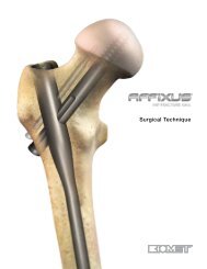
S3® Proximal Humerus Plate Shoulder Plating System - Biomet
S3® Proximal Humerus Plate Shoulder Plating System - Biomet
S3® Proximal Humerus Plate Shoulder Plating System - Biomet

Create successful ePaper yourself
Turn your PDF publications into a flip-book with our unique Google optimized e-Paper software.
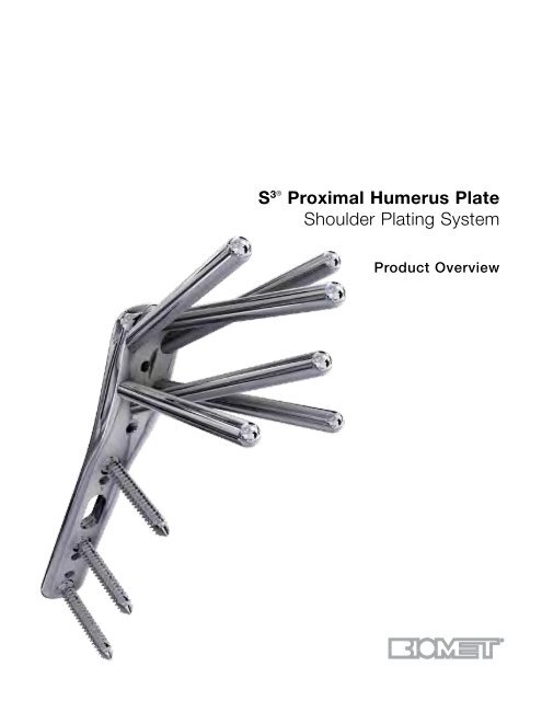
S 3®<br />
<strong>Proximal</strong> <strong>Humerus</strong> <strong>Plate</strong><br />
<strong>Shoulder</strong> <strong>Plating</strong> <strong>System</strong><br />
Product Overview
S 3® <strong>Proximal</strong> Humerous <strong>Plate</strong> <strong>Shoulder</strong> <strong>Plating</strong> <strong>System</strong><br />
Restoration of the Anatomy<br />
• Precisely contoured plates are designed to mirror the<br />
complex shape of the proximal humerus<br />
• The S3 plate is designed to act as a reduction template<br />
to help restore the anatomy<br />
• Multiple 4.0 mm subchondral support pegs & screws<br />
maintain fracture reduction<br />
Designed for Low Risk<br />
of Subacromial Impingement<br />
• The S3 plate is designed to be positioned approximately<br />
3.0 cm distal to the greater tuberosity, preventing<br />
subacromial impingement<br />
• Anatomically contoured undersurface aids in restoring<br />
proper humeral head rotation<br />
Strong and Stable Construct<br />
• Precise fixed angle peg distribution provides spatial<br />
subchondral support to resist varus forces throughout<br />
the full range of motion<br />
• <strong>Proximal</strong> and distal locking screws and pegs permit a<br />
strong interface for a secure and stable construct<br />
• Blunt-tipped subchondral support pegs provide stability<br />
while preventing protrusion through the articular<br />
surface<br />
Designed for Predictable<br />
and Reproducible Results<br />
• Central guiding K-wire provides visual confirmation for<br />
plate positioning<br />
• Manually inserted, blunt-tipped drill bits helps provide<br />
protection against the potential perforation of the articular<br />
surface<br />
• Predetermined peg trajectories allow a consistent<br />
spatial distribution within the humeral head<br />
2
Simplified Soft Tissue Fixation<br />
• Uniquely designed suture holes allow tuberosity repairs<br />
after humeral head fixation<br />
• Suture holes are designed to accomodate multiple<br />
passes for extensive soft tissue fixation<br />
F.A.S.T. Guide Technology<br />
• Pre-loaded single use disposable drill guides<br />
• No intraoperative assembly required, resulting in significant<br />
time savings<br />
• F.A.S.T. Guides are color-coded for easy plate identification:<br />
Red=Right / Lime=Left<br />
Surgical Technique Overview<br />
See Surgical Technique, Cat. No. 0612-00-565 for details of the complete procedure.<br />
Through a 12 cm to 14 cm incision, develop the deltopectoral<br />
interval.<br />
Debride then reduce the fracture through traction and<br />
manipulation.<br />
Position the plate approximately 3.0 cm distal to the<br />
greater tuberosity and just lateral to the bicipital groove.<br />
Secure the plate to the humeral shaft using a 3.8 mm<br />
multidirectional cortical screw through the oblong hole<br />
of the plate.<br />
While maintaining the reduction, place a 2.0 mm guide<br />
wire through the central hole at the head of the plate.<br />
Advance slowly and verify its trajectory under fluoroscopic<br />
imaging until it reaches 2-3 mm below the<br />
subchondral bone.<br />
Using the short 4.0 mm drill bit, drill under power<br />
through the F.A.S.T. Guides across the near cortex<br />
until the mechanical safety stop of the drill is reached.<br />
Manually advance the appropriate 4.0 mm long drill bit<br />
through the F.A.S.T. Guides under fluoroscopic imaging<br />
until 2-3 mm below the subchondral bone.<br />
Be sure to torque the proximal plate pegs so that they<br />
are fully seated. The head of a properly seated peg<br />
should sit beneath the surface of the plate.<br />
Using the end of the drill guide labeled “90°”, drill the<br />
remaining shaft screws. Then use a locking setscrew<br />
with each 90° locking shaft screw.<br />
Repair the tuberosities to the plate through the side<br />
loading suture attachment points.<br />
Evaluate the humerus under fluoroscopy to assess the<br />
final reduction and to confirm proper peg positioning.<br />
3
Peg and Screw Options:<br />
Item<br />
STP Series,<br />
Smooth Peg, Locking<br />
STPT Series,<br />
Threaded Peg, Locking<br />
NL-SS Series,<br />
90° Locking Setscrew<br />
NL Series,<br />
90° Cortical Screws,<br />
Non-locking<br />
MD Series,<br />
Multi-directional Cortical<br />
Screws, Non-locking<br />
Description<br />
Provides spatial subchondral support<br />
Helps capture and<br />
lag the humeral head<br />
Secures the 90° lock distal screws<br />
to the S3 <strong>Proximal</strong> <strong>Humerus</strong> <strong>Plate</strong><br />
Provide bi-cortical fixation while locking to the<br />
plate using the NL-SS setscrews<br />
Provide multi-directional fixation when used<br />
through the oblong hole<br />
S 3 Modular Tray:<br />
New fully modular tray system that<br />
offers intra-operative flexibility.<br />
• Multiple Applications<br />
• Reduced OR Clutter<br />
• Improved Workflow<br />
<strong>Plate</strong> Options:<br />
Item Description<br />
Head<br />
Width<br />
Shaft<br />
Width<br />
Overall<br />
Length<br />
S3 <strong>Proximal</strong> <strong>Humerus</strong> <strong>Plate</strong>, 3 Hole 16 mm 12 mm 71 mm<br />
S3 <strong>Proximal</strong> <strong>Humerus</strong> <strong>Plate</strong>, 4 Hole 16 mm 12 mm 84 mm<br />
S3 <strong>Proximal</strong> <strong>Humerus</strong> <strong>Plate</strong>, 6 Hole 16 mm 12 mm 109 mm<br />
S3 <strong>Proximal</strong> <strong>Humerus</strong> <strong>Plate</strong>, 8 Hole 16 mm 12 mm 150 mm<br />
S3 <strong>Proximal</strong> <strong>Humerus</strong> <strong>Plate</strong>, 11 Hole 16 mm 12 mm 195 mm<br />
S3 <strong>Proximal</strong> <strong>Humerus</strong> <strong>Plate</strong>, 14 Hole 16 mm 12 mm 246 mm<br />
Important:<br />
This Essential Product Information sheet does not include all of the information necessary for selection and use of a<br />
device. Please see full labeling for all necessary information.<br />
Indications:<br />
The S 3 <strong>Shoulder</strong> Fixation <strong>System</strong> is indicated for fractures and fracture dislocations, osteotomies, and non-unions of the<br />
proximal humerus.<br />
Contraindications:<br />
If any of the following are suspected, tests are to be performed prior to implantation. Active or latent<br />
infection. Sepsis. Insufficient quantity or quality of bone and/or soft tissue. Material sensitivity. Patients who are unwilling<br />
or incapable of following post operative care instructions.<br />
Warnings and Precautions:<br />
• Although the surgeon is the learned intermediary between the company and the patient, the important information<br />
conveyed in this document should be conveyed to the patient. The patient must be cautioned about the use, limitations<br />
and possible adverse effects of these implants. The patient must be warned that failure to follow postoperative<br />
care instructions may cause the implant or treatment to fail.<br />
• An implant must never be reused. Previous stresses may have created imperfections that can potentially lead<br />
to device failure. Protect implant appliances against scratching or nicking. Such stress concentration can lead to<br />
failure.<br />
• Orthopaedic instrumentation do not have an indefinite functional life. All re-usable instruments are subjected to<br />
repeated stresses related to bone contact, impaction, routine cleaning and sterilization processes. Instruments<br />
should be carefully inspected before each use to ensure that they are fully functional. Scratches or dents can result<br />
Essential Product Information<br />
in breakage. Dullness of cutting edges can result in poor functionality. Damaged instruments should be replaced to<br />
prevent potential patient injury such as metal fragments into the surgical site. Care should be taken to remove any<br />
debris, tissue or bone fragments that may collect on the instrument. Most instrument systems include inserts/trays<br />
and a container(s). Many instruments are intended for use with a specific implant system. It is essential that the<br />
surgeon and operating theatre staff are fully conversant with the appropriate surgical technique for the instruments<br />
and associated implant, if any.<br />
• Use fluoroscopy to prevent unintentional penetration of subchondral bone.<br />
• The distal end of the pegs should be 3-6 mm below the subchondral plate. Readjust as necessary.<br />
• Do NOT use unicortical screws (SNUS) with the shoulder plates. Use the SNUS with the SNP and the MD and NL<br />
series multi-directional and locking screws with the shoulder plates.<br />
• Ensure removal of all F.A.S.T. Guides after use.<br />
• Do NOT permanently implant K-wires through the holes of the plate as they may back out and cause tissue damage.<br />
Use of the K-wires allows you to provisionally secure the plates to the anatomy.<br />
• Supply a sufficient amount of torque to the pegs to ensure that each is fully seated. If not seated properly, remove,<br />
re-drill and reinsert the peg until fully seated. The head of the peg should sit beneath the surface of the plate to<br />
avoid soft tissue irritation.<br />
Adverse Effects:<br />
• The following are possible adverse effects of these implants: potential for these devices failing as a result of<br />
loose fixation and/or loosening, stress, excessive activity, load bearing particularly when the implants experience<br />
increased loads due to a delayed union, nonunion, or incomplete healing. Failure to follow postoperative care<br />
instructions may cause the implant or treatment to fail.<br />
All trademarks herein are the property of <strong>Biomet</strong>, Inc. or its subsidiaries unless<br />
otherwise indicated.<br />
For product information, including indications, contraindications, warnings, precautions<br />
and potential adverse effects, see the product labeling.<br />
This material is intended for the sole use and benefit of the <strong>Biomet</strong> sales force and<br />
physicians. It is not to be redistributed, duplicated or disclosed without the express<br />
written consent of <strong>Biomet</strong>.<br />
P.O. Box 587, Warsaw, IN 46581-0587 • 800.348.9500 x 1501<br />
©2012 <strong>Biomet</strong> Orthopedics • biomet.com<br />
Form No. BMET0019.0 • REV053112