Handbook of Energy Storage for Transmission or ... - W2agz.com
Handbook of Energy Storage for Transmission or ... - W2agz.com
Handbook of Energy Storage for Transmission or ... - W2agz.com

You also want an ePaper? Increase the reach of your titles
YUMPU automatically turns print PDFs into web optimized ePapers that Google loves.
EPRI Proprietary Licensed Material<br />
better represents the dynamic behavi<strong>or</strong> <strong>of</strong> the capacit<strong>or</strong>. The fastest response time is the<br />
discharge <strong>of</strong> C1 through R1, the second fastest is the discharge <strong>of</strong> C2 through R1 + R2,<br />
and so on. Because <strong>of</strong> the distributed charge st<strong>or</strong>age with distributed resistances, the<br />
capacit<strong>or</strong> can release only a small fraction <strong>of</strong> its total st<strong>or</strong>ed energy in very sh<strong>or</strong>t times.<br />
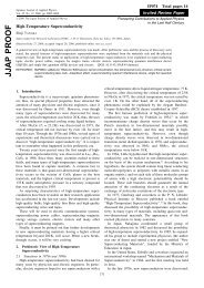
This is evident in the 2500 F example type II capacit<strong>or</strong> response shown in Figure 32. At<br />
longer times, m<strong>or</strong>e <strong>of</strong> the st<strong>or</strong>ed energy be<strong>com</strong>es available until, at very long times, all <strong>of</strong><br />
the st<strong>or</strong>ed energy can be accessed. Impedance data is <strong>com</strong>monly used to derive multiple<br />
time constant equivalent<br />
100<br />
% Total Capacitance<br />
80<br />
60<br />
40<br />
20<br />
0<br />
0.01 0.1 1 10<br />
Time Constant (s)<br />
Figure 32 Type II design, 2500F capacit<strong>or</strong> demonstrates dynamic characteristics <strong>of</strong> increased<br />
capacity with reduced loading and longer discharge times.<br />
Electrochemical capacit<strong>or</strong> response <strong>of</strong>ten has a second effect due to the p<strong>or</strong>osity <strong>of</strong> the<br />
electrodes themselves. Although particles in the electrode are typically large, interstitial<br />
space between these particles in thick electrodes creates multiple-time-constant behavi<strong>or</strong>.<br />
Consequently, an upper limit on the electrode thickness is usually established by the<br />
desired time response <strong>of</strong> the capacit<strong>or</strong>.<br />
Symmetric and Asymmetrical Electrodes<br />
Figure 33 summarizes some basic differences between the symmetric and the asymmetric<br />
capacit<strong>or</strong> designs using aqueous electrolytes. The symmetric capacit<strong>or</strong> uses the same<br />
material <strong>f<strong>or</strong></strong> both positive and the negative electrodes in approximately the same quantity,<br />
and produces two identical capacitances, each C o<br />
. Since these two capacit<strong>or</strong>s are<br />
connected in series, the total capacitance is 1/2 C o<br />
.<br />
In contrast, the asymmetric electrochemical capacit<strong>or</strong>s, as shown on the right side <strong>of</strong><br />
Figure 33, have positive and negative electrodes <strong>com</strong>prised <strong>of</strong> different materials. In fact,<br />
the positive electrode st<strong>or</strong>es charge m<strong>or</strong>e like a battery (Faradaic processes) so although<br />
physically smaller, its capacity is greater than the opposing double layer charge st<strong>or</strong>age<br />
electrode. There is enough space <strong>f<strong>or</strong></strong> the negative electrode to be sized <strong>f<strong>or</strong></strong> the total<br />
capacitance 2 C o<br />
in the single electrode. And, since it is mated with a much larger series<br />
capacit<strong>or</strong>, the total capacitance <strong>of</strong> this design is 2 C o<br />
. This difference, 1/2 C o<br />
<strong>f<strong>or</strong></strong> the<br />
symmetric and 2 C o<br />
<strong>f<strong>or</strong></strong> the asymmetric, gives a four-fold volumetric capacity advantage<br />
to the asymmetric designs.<br />
The voltage versus charge curve <strong>f<strong>or</strong></strong> each electrode is also shown in Figure 33. It<br />
provides in<strong>f<strong>or</strong></strong>mation on the exact operation <strong>of</strong> the capacit<strong>or</strong>. As charge is delivered to<br />
Electrochemical Capacit<strong>or</strong>s 61