RAD FCD-E1L pdf data sheet - Cutter Networks
RAD FCD-E1L pdf data sheet - Cutter Networks
RAD FCD-E1L pdf data sheet - Cutter Networks

You also want an ePaper? Increase the reach of your titles
YUMPU automatically turns print PDFs into web optimized ePapers that Google loves.
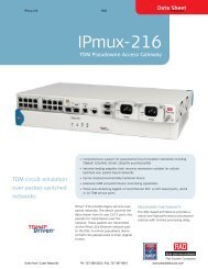
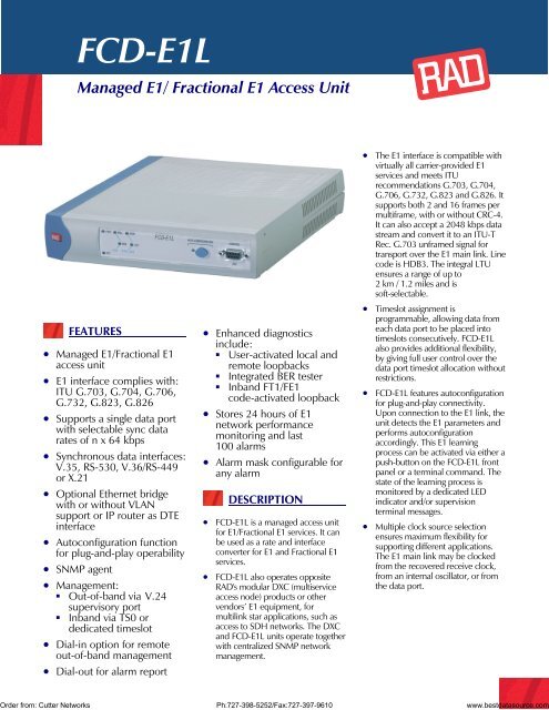
<strong>FCD</strong>-<strong>E1L</strong><br />
Managed E1/ Fractional E1 Access Unit<br />
FEATURES<br />
• Managed E1/Fractional E1<br />
access unit<br />
• E1 interface complies with:<br />
ITU G.703, G.704, G.706,<br />
G.732, G.823, G.826<br />
• Supports a single <strong>data</strong> port<br />
with selectable sync <strong>data</strong><br />
rates of n x 64 kbps<br />
• Synchronous <strong>data</strong> interfaces:<br />
V.35, RS-530, V.36/RS-449<br />
or X.21<br />
• Optional Ethernet bridge<br />
with or without VLAN<br />
support or IP router as DTE<br />
interface<br />
• Autoconfiguration function<br />
for plug-and-play operability<br />
• SNMP agent<br />
• Management:<br />
• Out-of-band via V.24<br />
supervisory port<br />
• Inband via TS0 or<br />
dedicated timeslot<br />
• Dial-in option for remote<br />
out-of-band management<br />
• Dial-out for alarm report<br />
• Enhanced diagnostics<br />
include:<br />
• User-activated local and<br />
remote loopbacks<br />
• Integrated BER tester<br />
• Inband FT1/FE1<br />
code-activated loopback<br />
• Stores 24 hours of E1<br />
network performance<br />
monitoring and last<br />
100 alarms<br />
• Alarm mask configurable for<br />
any alarm<br />
DESCRIPTION<br />
• <strong>FCD</strong>-<strong>E1L</strong> is a managed access unit<br />
for E1/Fractional E1 services. It can<br />
be used as a rate and interface<br />
converter for E1 and Fractional E1<br />
services.<br />
• <strong>FCD</strong>-<strong>E1L</strong> also operates opposite<br />
<strong>RAD</strong>'s modular DXC (multiservice<br />
access node) products or other<br />
vendors’ E1 equipment, for<br />
multilink star applications, such as<br />
access to SDH networks. The DXC<br />
and <strong>FCD</strong>-<strong>E1L</strong> units operate together<br />
with centralized SNMP network<br />
management.<br />
• The E1 interface is compatible with<br />
virtually all carrier-provided E1<br />
services and meets ITU<br />
recommendations G.703, G.704,<br />
G.706, G.732, G.823 and G.826. It<br />
supports both 2 and 16 frames per<br />
multiframe, with or without CRC-4.<br />
It can also accept a 2048 kbps <strong>data</strong><br />
stream and convert it to an ITU-T<br />
Rec. G.703 unframed signal for<br />
transport over the E1 main link. Line<br />
code is HDB3. The integral LTU<br />
ensures a range of up to<br />
2 km / 1.2 miles and is<br />
soft-selectable.<br />
• Timeslot assignment is<br />
programmable, allowing <strong>data</strong> from<br />
each <strong>data</strong> port to be placed into<br />
timeslots consecutively. <strong>FCD</strong>-<strong>E1L</strong><br />
also provides additional flexibility,<br />
by giving full user control over the<br />
<strong>data</strong> port timeslot allocation without<br />
restrictions.<br />
• <strong>FCD</strong>-<strong>E1L</strong> features autoconfiguration<br />
for plug-and-play connectivity.<br />
Upon connection to the E1 link, the<br />
unit detects the E1 parameters and<br />
performs autoconfiguration<br />
accordingly. This E1 learning<br />
process can be activated via either a<br />
push-button on the <strong>FCD</strong>-<strong>E1L</strong> front<br />
panel or a terminal command. The<br />
state of the learning process is<br />
monitored by a dedicated LED<br />
indicator and/or supervision<br />
terminal messages.<br />
• Multiple clock source selection<br />
ensures maximum flexibility for<br />
supporting different applications.<br />
The E1 main link may be clocked<br />
from the recovered receive clock,<br />
from an internal oscillator, or from<br />
the <strong>data</strong> port.<br />
Order from: <strong>Cutter</strong> <strong>Networks</strong> Ph:727-398-5252/Fax:727-397-9610 www.best<strong>data</strong>source.com
Order from: <strong>Cutter</strong> <strong>Networks</strong> Ph:727-398-5252/Fax:727-397-9610 www.best<strong>data</strong>source.com<br />
<strong>FCD</strong>-<strong>E1L</strong><br />
Managed E1/ Fractional E1 Access Unit<br />
• <strong>FCD</strong>-<strong>E1L</strong> features front panel LEDs<br />
to indicate transmit/receive activity,<br />
E1 signal loss condition and<br />
diagnostic loopback operation. The<br />
rear panel LEDs of the Ethernet<br />
interface modules indicate the LAN<br />
status and activity.<br />
• <strong>FCD</strong>-<strong>E1L</strong> is available as a<br />
standalone unit. A rack mount<br />
adapter kit enables installation of<br />
one or two (side by side) standalone<br />
units in a 19" rack (see Ordering).<br />
USER INTERFACES<br />
• <strong>FCD</strong>-<strong>E1L</strong> supports a wide range of<br />
digital interfaces: RS-530, V.35,<br />
X.21, and V.36/RS-449. In addition,<br />
<strong>FCD</strong>-<strong>E1L</strong> supports Ethernet<br />
interface modules with a built-in<br />
bridge (IR-ETH, IR-ETH/Q, IR-<br />
ETH/QN) or an IP router (IR-IP),<br />
which allow LAN-to-LAN<br />
connectivity over UTP or BNC<br />
media.<br />
• The synchronous <strong>data</strong> ports can<br />
operate in the following clock<br />
modes:<br />
• DCE: <strong>FCD</strong>-<strong>E1L</strong> provides both<br />
transmit and receive clocks with<br />
optional sampling of the<br />
incoming <strong>data</strong> with an inverted<br />
clock<br />
• DTE1: <strong>FCD</strong>-<strong>E1L</strong> provides<br />
transmit clock, attached<br />
equipment provides receive<br />
clock<br />
• DTE2: attached equipment<br />
provides both transmit and<br />
receive clocks<br />
APPLICATION<br />
• When equipped with IR-ETH,<br />
IR-ETH/Q or IR-ETH/QN interface<br />
modules, <strong>FCD</strong>-<strong>E1L</strong> transparently<br />
connects remote LANs, as well as<br />
VLANs, over unframed E1 links,<br />
utilizing the full E1 bandwidth, and<br />
filters Ethernet frames, forwarding<br />
only frames destined to the WAN.<br />
• The IR-ETH/QN port has the<br />
10/100BaseT interface and supports<br />
autonegotiation and VLAN frames.<br />
• <strong>FCD</strong>-<strong>E1L</strong> equipped with the IR-IP<br />
interface module operates as an IP<br />
gateway, forwarding IP packets<br />
destined to the IP network. This<br />
prevents broadcast to the WAN and<br />
enables the LAN users to register for<br />
an IP multicast group.<br />
• <strong>FCD</strong>-<strong>E1L</strong> with the IR-IP interface<br />
module connects the local IP<br />
networks to the public networks at<br />
full E1 speed, in contrast to<br />
connection over statistical protocols,<br />
such as Frame Relay.<br />
• The IR-ETH/QN port is available<br />
with 10/100BaseT interface. Other<br />
Ethernet ports are available with<br />
10BaseT (UTP) or 10Base2 (BNC)<br />
interfaces.<br />
MANAGEMENT & MAINTENANCE<br />
• Setup, control and monitoring of<br />
status and diagnostics<br />
information can be activated via:<br />
• ASCII terminal connected to the<br />
async control port<br />
• SNMP management connected<br />
to the async control port.<br />
• <strong>FCD</strong>-<strong>E1L</strong> has an internal SNMP<br />
agent and can be managed by any<br />
generic SNMP station or by the<br />
user-friendly, GUI-based <strong>RAD</strong>view<br />
SNMP network management<br />
application.<br />
• <strong>FCD</strong>-<strong>E1L</strong> supports both dial-in and<br />
dial-out modem connections via the<br />
serial V.24/RS-232 port, by using<br />
SLIP protocol or ASCII terminal<br />
command line interpreter. These<br />
connections can be used for remote<br />
out-of-band configuration and<br />
monitoring, as well as for sending<br />
callout alarm messages.<br />
• Inband management can be<br />
performed by using the spare bits<br />
(Sa bits) on Timeslot 0 (TS0) or by<br />
using a dedicated timeslot with the<br />
standard Frame Relay (RFC 1490)<br />
or <strong>RAD</strong> proprietary protocol. This<br />
allows setup, monitoring and<br />
diagnostics of the remote unit.<br />
Inband access by using spare bits on<br />
TS0 is possible only if these bits are<br />
passed transparently end-to-end.<br />
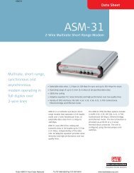
n x 64 kbps<br />
E1/FE1<br />
E1<br />
E1/FE1<br />
V.35, V.36<br />
G.703 Network<br />
X.21 <strong>FCD</strong>-<strong>E1L</strong> <strong>FCD</strong>-<strong>E1L</strong><br />
n x 64 kbps<br />
V.35<br />
NMS DXC V.36<br />
Router<br />
X.21
<strong>FCD</strong>-<strong>E1L</strong><br />
Managed E1/ Fractional E1 Access Unit<br />
• Maintenance capabilities include<br />
user-activated local and remote<br />
loopbacks at the E1 main link and<br />
<strong>data</strong> port. The user can also activate<br />
a BER test on the <strong>data</strong> port.<br />
Additionally, the <strong>data</strong> port responds<br />
to an ANSI FT1 inband loop code<br />
(RDL), generated from the remote<br />
<strong>FCD</strong>-<strong>E1L</strong> or DXC in a specific bundle<br />
of timeslots allocated only to that<br />
port.<br />
• When operating with CRC-4, E1<br />
network statistics are stored in<br />
memory, according to RFC 1406.<br />
The statistic information may be<br />
retrieved locally, through the control<br />
port.<br />
SPECIFICATIONS<br />
E1 INTERFACE<br />
• Framing<br />
• 256N (no MF, CCS)<br />
• 256N (no MF, CCS) with CRC-4<br />
• 256S (TS16 MF, CAS)<br />
• 256S (TS16 MF CAS) with CRC-4<br />
• Unframed<br />
• Bit Rate<br />
2.048 Mbps<br />
• Line Code<br />
HDB3<br />
• Impedance<br />
120Ω, balanced<br />
75Ω, unbalanced<br />
• Signal Level<br />
Receive:<br />
0 to -36 dB with LTU<br />
0 to -10 dB without LTU<br />
Transmit:<br />
±3V (±10%), balanced<br />
±2.37V (±10%), unbalanced<br />
• Jitter/Wander<br />
As per ITU G.823,<br />
ETSI TBR-12 and TBR-13<br />
• Connectors<br />
RJ-45, 8-pin, balanced<br />
Two BNC coaxial, unbalanced<br />
• Transmit Timing<br />
Locked to the nodal clock<br />
• Compliance<br />
ITU G.703, G.704, G.706, G.732<br />
• Performance Monitoring<br />
Local support of CRC-4<br />
Statistics according to RFC 1406<br />
and G.826<br />
DATA PORT<br />
• Connectors<br />
D-type 25-pin RS-530, female<br />
V.35, X.21, and V.36/RS-449.<br />
• Data Rate<br />
n x 64 kbps (n=1,2...,31)<br />
• Clock Modes<br />
DCE: RX and TX clock to user<br />
device<br />
DTE1: RX clock to user device;<br />
TX clock from user device<br />
DTE2: RX and TX clock from user<br />
device<br />
• Control Signals<br />
• CTS follows RTS or constantly<br />
ON, soft-selectable<br />
• DSR constantly ON, unless in test<br />
mode<br />
• DCD constantly ON, unless in<br />
sync loss<br />
ETHERNET BRIDGE/ROUTER PORT<br />
Refer to Table 1 below.<br />
• Connectors<br />
10BaseT (UTP): Shielded RJ-45<br />
10/100BaseT (UTP): Shielded RJ-45<br />
10Base2 (BNC): Two BNC coaxial<br />
(not for IR-ETH/QN)<br />
GENERAL<br />
• Nodal Clock<br />
Internal clock:<br />
±50 ppm<br />
Loopback timing:<br />
±130 ppm<br />
External timing from <strong>data</strong> port:<br />
±130 ppm<br />
• Diagnostics<br />
• Main E1 link:<br />
Local and remote loopback<br />
• Data port:<br />
Local <strong>data</strong> port loopback<br />
Remote <strong>data</strong> port loopback<br />
BER test<br />
Inband code activated loopback<br />
• Timeslot Allocation<br />
Consecutive (bundled)<br />
User-defined<br />
• Management Port<br />
• Interface and Connector:<br />
V.24/RS-232, 9-pin D-type,<br />
female<br />
• Format: Asynchronous<br />
• Baud rate: 1.2-19.2 kbps,<br />
autobaud<br />
• Character: 8 bit no parity, 7 bit<br />
odd or even parity<br />
Table 1. Ethernet Interface Modules Characteristics<br />
Interface LAN Table Filtering & Buffer Delay Line Code<br />
WAN Protocol<br />
Module<br />
Forwarding<br />
[addresses] [frames per second] [frames] [frames]<br />
IR-ETH 10,000 15,000 256 1 Manchester HDLC<br />
IR-ETH/Q 2,000 2,000 256 1 Manchester HDLC<br />
IR-ETH/QN 1,024 150,000 85 1 • 10BaseT: Manchester HDLC<br />
• 100BaseT: MLT3<br />
IR-IP – – 256 1 Manchester • PPP (PAP/CHAP)<br />
• Frame Relay<br />
(RFC 1490)<br />
• HDLC<br />
Note: All the Ethernet interface modules conform to the IEEE 802.3/Ethernet V2 standard. Additionally, IR-ETH/Q<br />
supports IEEE 802.1/q frames, and IR-ETH/QN conforms to IEEE 802.1q (relevant parts), 802.1p and 802.3x.<br />
Order from: <strong>Cutter</strong> <strong>Networks</strong> Ph:727-398-5252/Fax:727-397-9610 www.best<strong>data</strong>source.com
<strong>FCD</strong>-<strong>E1L</strong><br />
Managed E1/ Fractional E1 Access Unit<br />
• Indicators<br />
PWR : Power is ON<br />
TST: Test is active<br />
ALM MAJ: Major alarm condition<br />
ALM MIN: Minor alarm condition<br />
LOC SYNC LOSS: Local loss of<br />
synchronization on the E1 link<br />
REM SYNC LOSS: Remote loss of<br />
synchronization on the E1 link<br />
AUTO CONFIGURATION:<br />
Monitors E1 learning process<br />
• Front Panel Controls<br />
AUTO CONFIGURATION<br />
push-button<br />
• Alarms<br />
Last 100 alarms are stored and<br />
available for retrieval. Each alarm<br />
is time stamped.<br />
• Physical<br />
Height: 44 mm / 1.75 in<br />
Width: 215 mm / 8.5 in<br />
Depth: 243 mm / 9.6 in<br />
Weight 0.9 kg / 2.0 lb<br />
• Power<br />
AC: 100 to 240 VAC; 47 to 63 Hz<br />
DC: -48 VDC (36 to 72 VDC)<br />
Power consumption: 5W max.<br />
• Environment<br />
Temperature: 0-50°C / 32-122°F<br />
Humidity: up to 90%,<br />
non condensing<br />
ORDERING<br />
<strong>FCD</strong>-<strong>E1L</strong>/*/~/&<br />
E1/Fractional E1 Access Unit<br />
* Specify main link interface:<br />
B for balanced with RJ-45<br />
connector<br />
U for unbalanced with BNC<br />
connector<br />
~ Specify power supply voltage:<br />
AC for 110 VAC to 240 VAC<br />
48 for -48 VDC<br />
& Specify <strong>data</strong> port interface:<br />
530 for RS-530 interface<br />
V35 for V.35 interface<br />
X21 for X.21 interface<br />
449 for RS-449 interface<br />
ETUB for UTP Ethernet bridge<br />
(10BaseT)<br />
ETBB for BNC Ethernet bridge<br />
(10Base2)<br />
ETUQ for UTP Ethernet bridge<br />
VLAN (10BaseT)<br />
ETBQ for BNC Ethernet bridge<br />
VLAN (10Base2)<br />
ETQN for UTP Ethernet bridge<br />
VLAN (10/100BaseT)<br />
ETUR for UTP Ethernet router<br />
(10BaseT)<br />
ETBR for BNC Ethernet router<br />
(10Base2)<br />
CABLES<br />
The following cables convert the 25-pin<br />
channel connector into the respective<br />
interface. Cable length is 6 ft (2m),<br />
unless otherwise indicated.<br />
CBL-HS2V1 to connect a V.35 DTE<br />
using DCE clock mode<br />
CBL-HS2V2 to connect a V.35 DCE<br />
using DTE1 clock mode<br />
CBL-HS2V3 to connect a V.35 DCE<br />
using DTE2 clock mode<br />
CBL-HS2R1 to connect an RS-449<br />
(V.36) DTE using DCE<br />
clock mode<br />
CBL-HS2R2 to connect an RS-449<br />
(V.36) DCE using DTE1<br />
clock mode<br />
CBL-HS2R3 to connect an RS-449<br />
(V.36) DCE using DTE2<br />
clock mode<br />
CBL-HS2X1 to connect an X.21 DTE<br />
using DCE clock mode<br />
Note: Cables for DCE clock mode are<br />
supplied in accordance with order.<br />
Cables for DTE1 and DTE2 clock<br />
modes are to be ordered separately.<br />
RM-28<br />
Hardware for mounting one or two<br />
units in a 19" rack<br />
165-100-09/02<br />
© 1991–2002 <strong>RAD</strong> Data Communications Ltd. Specifications are subject to change without prior notice.<br />
Order from: <strong>Cutter</strong> <strong>Networks</strong> Ph:727-398-5252/Fax:727-397-9610 www.best<strong>data</strong>source.com