Emergency stop module BD 5987 - ELTRON
Emergency stop module BD 5987 - ELTRON
Emergency stop module BD 5987 - ELTRON

Create successful ePaper yourself
Turn your PDF publications into a flip-book with our unique Google optimized e-Paper software.
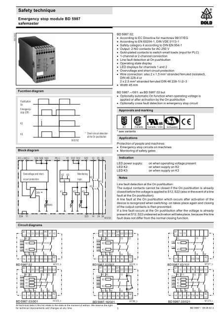
Safety technique<br />
<strong>Emergency</strong> <strong>stop</strong> <strong>module</strong> <strong>BD</strong> <strong>5987</strong><br />
safemaster<br />
0221553<br />
<strong>BD</strong> <strong>5987</strong>.02:<br />
· According to EC Directive for machines 98/37/EG<br />
· According to EN 60204-1, DIN VDE 0113-1<br />
· Safety category 4 according to DIN EN 954-1<br />
· Output: 2 NO contacts for AC 250 V<br />
· Gold-plated contacts to switch small loads (input for PLC)<br />
· 1-channel or 2-channel connection<br />
· Line fault detection at On pushbutton<br />
· Operating state display<br />
· LED displays for channels 1 and 2<br />
· Overvoltage and short circuit protection<br />
· Wire connection: also 2 x 1,5 mm 2 stranded ferruled (isolated),<br />
DIN 46 228-4 or<br />
2 x 2,5 mm 2 stranded ferruled DIN 46 228-1/-2/-3<br />
· Width 45 mm<br />
Fucntion diagram<br />
Pushbutton<br />
On<br />
<strong>Emergency</strong><strong>stop</strong><br />
(Off)<br />
K2<br />
K3<br />
Block diagram<br />
*<br />
M 6742<br />
* Short-circuit detection<br />
at the On pushbutton<br />
<strong>BD</strong> <strong>5987</strong>.--/001: as <strong>BD</strong> <strong>5987</strong>.02 but<br />
· Optionally automatic On function when operating voltage is<br />
applied or after activation by the On pushbutton<br />
· Optionally cross fault detection in emergency <strong>stop</strong> circuit<br />
Approvals and marking<br />
ET Canada<br />
* see variants<br />
Applications<br />
*<br />
Canada / USA<br />
Protection of people and machines<br />
· <strong>Emergency</strong> <strong>stop</strong> circuits on machines<br />
· Monitoring of safety gates<br />
Schweden<br />
A1(+) A2(-) S33 S33 S33 PE(-) Y2 S12 S12 S22 13 23 33<br />
Overvoltage and shortcircuit<br />
K2 K3 Monitoring<br />
protection<br />
&<br />
logic<br />
K2<br />
K1<br />
K3<br />
24V ...<br />
K1 K2 K3<br />
Mains<br />
S34 Y1<br />
S23 14 24 34<br />
M 6758<br />
Indication<br />
LED power supply:<br />
LED K2:<br />
LED K3:<br />
Notes<br />
on when operating voltage present<br />
on when supply on K2<br />
on when supply on K3<br />
Line fault detection at the On pushbutton:<br />
The output contacts cannot be closed if the On pushbutton is already<br />
closed before the voltage is applied to S12, S22 (also in the event of a line<br />
fault at the On pushbutton).<br />
A line fault at the On pushbutton which occurs after activation of the<br />
device is recognized when switching- on takes place again and closing<br />
of the output contacts is then prevented.<br />
If a line fault occurs at the On pushbutton after the voltage is already<br />
present at S12, S22 undesired activation will take place, because this line<br />
fault does not differ from the normal closing function.<br />
Circuit diagrams<br />
A1<br />
PE<br />
A1<br />
S21<br />
A1<br />
13 23 S22 S33 Y1 Y2<br />
13 23 S12 S22 S23 S33<br />
(+)<br />
(-)<br />
(+)<br />
/PE<br />
(+)<br />
13 23<br />
A1 Y1<br />
13 23<br />
A1 X5<br />
13 23<br />
A1<br />
13 23<br />
S12<br />
S12<br />
T33<br />
S22 K2<br />
S22 K2<br />
K2<br />
S33<br />
S33<br />
T34<br />
S34 K3<br />
S34 K3<br />
K3<br />
A2 Y2 PE 14 24<br />
A2 X6 PE 14 24<br />
A2<br />
14 24<br />
14<br />
A2<br />
A2<br />
A2<br />
24 S12 S12 S33 S33 S34<br />
14 24 S12 S33 X5 X6 S34<br />
14 24 T33 T34<br />
(-)<br />
(-)<br />
(-)<br />
<strong>BD</strong> <strong>5987</strong>.02 M7375_b<br />
<strong>BD</strong> <strong>5987</strong>.02/001 M7376_b<br />
<strong>BD</strong> <strong>5987</strong>.02/101<br />
M7377_b<br />
A1<br />
S21<br />
A1<br />
S21<br />
A1<br />
13 23 S12 S22 S23 S33<br />
13 21 S12 S22 S23 S33<br />
(+)<br />
/PE<br />
(+)<br />
/PE<br />
(+)<br />
13 23 T12 PE T22 S23 T11<br />
S12<br />
A1 X5 13 23 33<br />
S12<br />
A1 X5<br />
13 21<br />
T12<br />
A1 T11 13 23 33<br />
S22<br />
S33<br />
S34<br />
K2<br />
K1<br />
K3<br />
S22<br />
S33<br />
S34<br />
K2<br />
K3<br />
T22<br />
T33<br />
T34<br />
K2<br />
K1<br />
K3<br />
A2 X6 PE 14 24 34<br />
A2 X6 PE 14 22<br />
A2 X6 PE 14 24 34<br />
14 24 33 34 X5<br />
A2<br />
A2<br />
A2<br />
X6 S34<br />
(-)<br />
14 22 S12 S33 X5 X6 S34<br />
14 24 33 34 T33 X6 T34<br />
(-)<br />
(-)<br />
<strong>BD</strong> <strong>5987</strong>.03/001 M7378_b<br />
<strong>BD</strong> <strong>5987</strong>.16/001 M7380_b<br />
<strong>BD</strong> <strong>5987</strong>.03/021<br />
M7379_c<br />
All technical data in this list relate to the state at the moment of edition. We reserve the right<br />
for technical improvements and changes at any time.<br />
1<br />
<strong>BD</strong> <strong>5987</strong> / 09.09.02 d
Notes<br />
The gold-plated contacts of the <strong>BD</strong> <strong>5987</strong> mean that this <strong>module</strong> is also<br />
suitable for switching small loads of 1 mVA ... 7 VA, 1 mW ... 7 W in the<br />
range 0,1 ... 60 V, 1 ... 300 mA. The contacts also permit the maximum<br />
switching current. However, since the gold plating will be burnt off at this<br />
current level, the device is no longer suitable for switching small loads<br />
after this.<br />
The PE terminal permits operation of the device in IT systems with<br />
insulation monitoring and also serves as a reference point for testing the<br />
control voltage. The internal short-circuit protection will be bridged on DC<br />
devices, if the protective ground is connected to terminal PE.<br />
One or more extension <strong>module</strong>s BN 5989 or external contactors with<br />
positively-driven contacts may be used to multiply the number of contacts<br />
of the emergency <strong>stop</strong> <strong>module</strong> <strong>BD</strong> <strong>5987</strong>.<br />
For automatic restart:<br />
S22 must be connected before S12. S12 initiates the automatic restart.<br />
With manual restart it is not necessary to follow this order.<br />
Technical data<br />
Input<br />
Nominal voltage U N<br />
:<br />
Voltage range:<br />
at 10% residual ripple:<br />
at 48% residual ripple:<br />
Nominal consumption:<br />
Nominal frequency:<br />
Control voltage at S33:<br />
Control current<br />
<strong>BD</strong> <strong>5987</strong>.02:<br />
<strong>BD</strong> <strong>5987</strong>.02/001:<br />
Minimum voltage at<br />
terminals S12, S22:<br />
Recovery time:<br />
Output<br />
AC 24, 48, 110, 127, 230, 240 V<br />
DC 24 V<br />
AC 0,8 ... 1,1 U N<br />
DC 0,9 ... 1,2 U N<br />
DC 0,8 ... 1,1 U N<br />
approx. 5,5 VA<br />
50 / 60 Hz<br />
DC 24 V<br />
typ. DC 55 mA<br />
typ. DC 45 mA<br />
DC 21 V with activated device<br />
0,5 s after release of the emergency<br />
<strong>stop</strong> pushbutton<br />
Contacts<br />
<strong>BD</strong> <strong>5987</strong>.02:<br />
2 NO contacts<br />
Operate time:<br />
max. 100 ms<br />
<strong>BD</strong> <strong>5987</strong>.02/001:<br />
with automatic restart approx. 1 s<br />
Release time<br />
Opening in secondary<br />
circuit (S12-S22): 50 ms ± 25 %<br />
Opening in supply circuit<br />
<strong>BD</strong> <strong>5987</strong>.02: 350 ms ± 50 %<br />
<strong>BD</strong> <strong>5987</strong>.02/001: 120 ms ± 50 %<br />
Contact type:<br />
relay, positively-driven<br />
Nominal output voltage: AC 250 V<br />
DC: see limit curve for arc-free<br />
operation<br />
Thermal current I th<br />
: see continuous current limit curve<br />
(max. 10 A in one contact path)<br />
Switching capacity<br />
to AC 15: 5 A / AC 230 V EN 60 947-5-1<br />
for NO contact<br />
2 A / AC 230 V EN 60 947-5-1<br />
for NC contact<br />
Electrical life:<br />
to AC 15 at 2 A, AC 230 V: 10 5 switching cycles EN 60 947-5-1<br />
Permissible operating<br />
frequency:<br />
600 switching cycles / h<br />
Short circuit strength<br />
max. fuse rating: 6 A gL EN 60 947-5-1<br />
Mechanical life:<br />
10 x 10 6 switching cycles<br />
General data<br />
Operating mode:<br />
Continuous operation<br />
Temperature range: - 15 ... + 55°C<br />
at max. 90 % humidity<br />
Clearance and creepage<br />
distances<br />
overvoltage category /<br />
contamination level: 4 kV / 2 IEC 60 664-1<br />
Technical data<br />
EMC<br />
Electrostatic discharge: 8 kV (air) EN 61 000-4-2<br />
HF irradiation: 10 V / m EN 61 000-4-3<br />
Fast transients: 2 kV EN 61 000-4-4<br />
Surge voltages<br />
between<br />
wires for power supply: 1 kV EN 61 000-4-5<br />
between wire and ground: 2 kV EN 61 000-4-5<br />
Interference suppression: Limit value class B EN 55 011<br />
Degree of protection: Housing: IP 40 EN 60 529<br />
Terminals: IP 20 EN 60 529<br />
Housing:<br />
Thermoplastic with V0 behaviour<br />
according to Ul subject 94<br />
Vibration resistance: Amplitude 0,35 mm EN 60 068-2-6<br />
frequency 10 ... 55 Hz<br />
Climate resistance: 15 / 055 / 04 EN 60 068-1<br />
Terminal designation: EN 50 005<br />
Wire connection:<br />
Wire fixing:<br />
1 x 4 mm 2 solid or<br />
1 x 2,5 mm 2 stranded ferruled (isolated)<br />
or<br />
2 x 1,5 mm 2 stranded ferruled (isolated)<br />
DIN 46 228-1/-2/-3/-4 or<br />
2 x 2,5 mm 2 stranded ferruled<br />
DIN 46 228-1/-2/-3<br />
Plus-minus terminal scews<br />
M3.5 box terminal with wire protection<br />
Mounting: DIN rail EN 50 022<br />
Weight:<br />
450 g<br />
Dimensions<br />
Width x height x depth:<br />
Standard type<br />
45 x 74 x 121 mm<br />
<strong>BD</strong> <strong>5987</strong>.02/001 DC 24 V<br />
Article number: 0040954 stock item<br />
· Output: 2 NO contacts<br />
· Optionally automatic On function when operating voltage is applied<br />
or after activation by the On pushbutton<br />
· Nominal voltage U N<br />
: DC 24 V<br />
· Width 45 mm<br />
Variants<br />
<strong>BD</strong> <strong>5987</strong>.02/60:<br />
<strong>BD</strong> <strong>5987</strong>.02/61:<br />
<strong>BD</strong> <strong>5987</strong>.02/001:<br />
with CSA approval<br />
with UL approval (Canada/USA)<br />
Optionally cross fault monitoring on the<br />
emergency <strong>stop</strong> loop (see application M6749)<br />
Jumper asignment for functions:<br />
Activation via On pushbutton / or automatic On function<br />
On pushbutton Jumper Function<br />
S12-S34 or<br />
S33-S34<br />
X5 - X6<br />
• • • •<br />
• • • •<br />
The output contacts are switched<br />
only after operation of the On pushbutton.<br />
Line fault monitoring at the On pushbutton.<br />
Automatic On function for operating<br />
voltage Off/On or after emergency<strong>stop</strong><br />
release<br />
<strong>BD</strong> <strong>5987</strong>.03/001: with 2 NO contacts,<br />
1 signalling contact AC/DC 0,1 ... 1 A / 10 ...120 V<br />
<strong>BD</strong> <strong>5987</strong>.16/001: with 1 NO contact, 1 NC contact<br />
<strong>BD</strong> <strong>5987</strong>.02/101: see <strong>BD</strong> <strong>5987</strong>.02/001,<br />
but with special terminal arrangement<br />
<strong>BD</strong> <strong>5987</strong>.03/201: see <strong>BD</strong> <strong>5987</strong>.03/001,<br />
but with special terminal designation<br />
2
Variants<br />
Jumper asignment for functions:<br />
Activation via On pushbutton / or automatic On function<br />
On pushbutton Jumper Function<br />
T11-T34 or T33-X6<br />
T12-T34<br />
• • • •<br />
• • • •<br />
Ordering example for Variants<br />
<strong>BD</strong> <strong>5987</strong> .02 /_ _ _ AC 230 V 50/60 Hz<br />
Characteristics<br />
I(A)<br />
7<br />
6<br />
5<br />
4<br />
3<br />
2<br />
1<br />
0<br />
10<br />
20 30 40 50<br />
Continuous current limit curve<br />
(Current via two contact rows)<br />
60<br />
T( C)<br />
M6759<br />
The output contacts are switched<br />
only after operation of the On pushbutton.<br />
Line fault monitoring at the On pushbutton.<br />
Automatic On function for operating<br />
voltage Off/On or after emergency<strong>stop</strong><br />
release<br />
Switching voltage U [V]<br />
250<br />
200<br />
150<br />
100<br />
50<br />
Nominal frequency<br />
Nominal voltage<br />
Variant, if required<br />
Contacts<br />
Type<br />
0<br />
1 2 3 4 5 6 7 8 9 10<br />
Switching current I [A]<br />
M 6732<br />
Limit curve for arc-free<br />
operation with resistive load<br />
Application examples<br />
L1<br />
Two-channel emergeny <strong>stop</strong> circuit<br />
L1<br />
On<br />
E---<br />
E---<br />
A1(+) S34 S33 S33 S33 PE(-) Y2 S12 S12 S22 13 23<br />
A2(-)<br />
N<br />
One-channel emergency <strong>stop</strong> circuit. This circuit does not have any<br />
redundancy in the emergency <strong>stop</strong> control circuit<br />
L1<br />
N<br />
Y1 14 24<br />
E---<br />
Off<br />
E------------<br />
<strong>Emergency</strong><strong>stop</strong><br />
<strong>Emergency</strong><strong>stop</strong><br />
On<br />
E---<br />
<strong>BD</strong> <strong>5987</strong><br />
On E---<br />
Off<br />
E- - - - -<br />
<strong>Emergency</strong><strong>stop</strong><br />
A1(+) S34 S33 S33 S33 PE(-) Y2 S12 S12 S22 13 23<br />
A2(-)<br />
N<br />
<strong>BD</strong> <strong>5987</strong><br />
E------------<br />
Y1 14 24<br />
M 6744<br />
M 6743<br />
A1(+) S34 S33 S33 S33 PE(-) Y2 S12 S12 S22 13 23<br />
<strong>BD</strong> <strong>5987</strong><br />
A2(-)<br />
Y1 14 24<br />
M 6745<br />
Two-pole emergency <strong>stop</strong> circuit with emergency <strong>stop</strong> control device in<br />
supply circuit.<br />
Application for long emergency <strong>stop</strong> loops where the control voltage<br />
drops below the minimum voltage of 21 V.<br />
Attention:<br />
Single faults (e.g. line faults at the emergency <strong>stop</strong> control device) are not<br />
detected with this external circuit configuration<br />
L1<br />
K4<br />
<strong>Emergency</strong><strong>stop</strong><br />
On<br />
E---<br />
K5<br />
E------------<br />
A1(+) S34 S33 S33 S33 PE(-) Y2<br />
S12 S12 S22 13 23<br />
<strong>BD</strong> <strong>5987</strong><br />
A2(-)<br />
Y1 14<br />
24<br />
K4<br />
K5<br />
N<br />
M 6746<br />
Contact reinforcement by external contactors, 2-channel.<br />
The output contacts can be reinforced by external contactors with<br />
positively-driven contacts for switching currents > 10 A. Functioning of<br />
the external contactors is monitored by looping the NC contacts into the<br />
closing circuit (terminals Y2 - S12).<br />
3
Application examples<br />
L1<br />
K4<br />
<strong>Emergency</strong><strong>stop</strong><br />
On<br />
E---<br />
K5<br />
E------------<br />
A1(+) S34 S33 S33 S33 PE(-) Y2<br />
S12 S12 S22 13 23<br />
<strong>BD</strong> <strong>5987</strong><br />
A2(-)<br />
Y1 14<br />
24<br />
K4<br />
K5<br />
N<br />
M 6747<br />
Contact reinforcement by external contactors with reduced safety level<br />
L1<br />
On<br />
E---<br />
S1<br />
S2<br />
safety gate<br />
closed<br />
A1(+) S34 S33 S33 S33 PE(-) Y2 S12 S12 S22<br />
13 23<br />
<strong>BD</strong> <strong>5987</strong><br />
A2(-)<br />
N<br />
Y1 14 24<br />
Activated NO contact<br />
(contact position: closed)<br />
M6748_a<br />
Two-channel monitoring of a safety gate<br />
L1<br />
<strong>Emergency</strong><strong>stop</strong><br />
E---------------------------<br />
A1(+) 13<br />
23 S12 S21,PE<br />
S22<br />
S23<br />
S33<br />
<strong>BD</strong> <strong>5987</strong>.02/001<br />
14<br />
24 S12 S33 X5 X6 S34 A2(-)<br />
On<br />
E---<br />
N<br />
M 6749<br />
Two-channel emergency <strong>stop</strong> circuit with cross fault detection.<br />
Activation via On pushbutton. ---- Jumper X5 -X6:<br />
Jumper X5 - X6 must be fitted for the automatic On function.<br />
The On pushbutton is not required<br />
L1<br />
<strong>Emergency</strong><strong>stop</strong><br />
E-------------------<br />
A1(+) 13<br />
23 S12 S21,PE<br />
S22<br />
S23<br />
S33<br />
<strong>BD</strong> <strong>5987</strong>.02/001<br />
14<br />
24 S12 S33 X5 X6 S34 A2(-)<br />
On<br />
E---<br />
N<br />
M 6750<br />
Two-channel emergency-<strong>stop</strong> circuit without cross fault detection.<br />
Activation via On pushbutton. ---- Jumper X5 - X6:<br />
Jumper X5 - X6 must be fitted for the automatic On function.<br />
The On pushbutton is not required<br />
E. DOLD & SÖHNE KG • D-78114 Furtwangen<br />
e-mail dold-relays@t-online.de • internet http://www.dold.com<br />
• Postf. 1251 • Tel. +49 7723 654 0 • Telefax +49 7723 654 356<br />
4