

GV Series Gas Valves Data Sheet - Trend
GV Series Gas Valves Data Sheet - Trend
GV Series Gas Valves Data Sheet - Trend

Create successful ePaper yourself
Turn your PDF publications into a flip-book with our unique Google optimized e-Paper software.
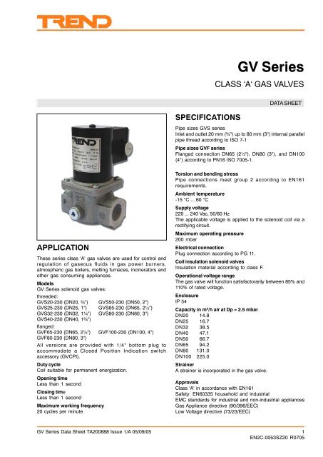
<strong>GV</strong> <strong>Series</strong><br />
CLASS ‘A‘ GAS VALVES<br />
SPECIFICATIONS<br />
DATA SHEET<br />
Pipe sizes <strong>GV</strong>S series<br />
Inlet and outlet 20 mm (¾") up to 80 mm (3") internal parallel<br />
pipe thread according to ISO 7-1<br />
Pipe sizes <strong>GV</strong>F series<br />
Flanged connection DN65 (2½"), DN80 (3"), and DN100<br />
(4") according to PN16 ISO 7005-1.<br />
APPLICATION<br />
These series class 'A' gas valves are used for control and<br />
regulation of gaseous fluids in gas power burners,<br />
atmospheric gas boilers, melting furnaces, incinerators and<br />
other gas consuming appliances.<br />
Models<br />
<strong>GV</strong> <strong>Series</strong> solenoid gas valves:<br />
threaded:<br />
<strong>GV</strong>S20-230 (DN20, ¾") <strong>GV</strong>S50-230 (DN50, 2")<br />
<strong>GV</strong>S25-230 (DN25, 1") <strong>GV</strong>S65-230 (DN65, 2½")<br />
<strong>GV</strong>S32-230 (DN32, 1¼") <strong>GV</strong>S80-230 (DN80, 3")<br />
<strong>GV</strong>S40-230 (DN40, 1¾")<br />
flanged:<br />
<strong>GV</strong>F65-230 (DN65, 2½") <strong>GV</strong>F100-230 (DN100, 4")<br />
<strong>GV</strong>F80-230 (DN80, 3")<br />
All versions are provided with 1/4" bottom plug to<br />
accommodate a Closed Position Indication switch<br />
accessory (<strong>GV</strong>CPI).<br />
Duty cycle<br />
Coil suitable for permanent energization.<br />
Opening time<br />
Less than 1 second<br />
Closing time<br />
Less than 1 second<br />
Maximum working frequency<br />
20 cycles per minute<br />
Torsion and bending stress<br />
Pipe connections meet group 2 according to EN161<br />
requirements.<br />
Ambient temperature<br />
-15 °C ... 60 °C<br />
Supply voltage<br />
220 ... 240 Vac, 50/60 Hz<br />
The applicable voltage is applied to the solenoid coil via a<br />
rectifying circuit.<br />
Maximum operating pressure<br />
200 mbar<br />
Electrical connection<br />
Plug connection according to PG 11.<br />
Coil insulation solenoid valves<br />
Insulation material according to class F.<br />
Operational voltage range<br />
The gas valve will function satisfactorarily between 85% and<br />
110% of rated voltage.<br />
Enclosure<br />
IP 54<br />
Capacity in m 3 /h air at Dp = 2.5 mbar<br />
DN20 14.8<br />
DN25 16.7<br />
DN32 38.5<br />
DN40 47.1<br />
DN50 66.7<br />
DN65 94.2<br />
DN80 131.0<br />
DN100 225.0<br />
Strainer<br />
A strainer is incorporated in the gas valve.<br />
Approvals<br />
Class 'A' in accordance with EN161<br />
Safety: EN60335 household and industrial<br />
EMC standards for industrial and non-industrial appliances<br />
<strong>Gas</strong> Appliance directive (90/396/EEC)<br />
Low Voltage directive (73/23/EEC)<br />
<strong>GV</strong> <strong>Series</strong> <strong>Data</strong> <strong>Sheet</strong> TA200888 Issue 1/A 05/09/05 1<br />
EN2C-0053SZ20 R0705
<strong>GV</strong> <strong>Series</strong><br />
INSTALLATION<br />
WARNING<br />
• Take care that installer is a trained experienced<br />
service man.<br />
• Turn off gas supply before starting installation.<br />
• Disconnect power supply to prevent electrical<br />
shock and/or equipment damage.<br />
Mounting position<br />
The gas valve may be mounted in any position between<br />
plus or minus 90 degrees from the vertical.<br />
Mounting location<br />
The distance between the gas valve and the wall/ground,<br />
must be at least 30 cm.<br />
Main gas connection threaded valves<br />
• Take care that dirt cannot enter the gas valve during<br />
handling.<br />
• Ensure the gas flows in the same direction as the arrow<br />
on the housing of the gas valve.<br />
• Use a sound taper fitting with thread according to ISO 7-1<br />
(BS 21, DIN 2999) or a piece of new properly reamed pipe,<br />
free from swarf.<br />
• Do not thread or tighten the pipe or pipe fitting too far,<br />
otherwise valve distortion and malfunction could result.<br />
• Apply a moderate amount of good quality thread<br />
compound to the pipe or fitting only, leaving the two end<br />
threads bare; PTFE tape may be used as an alternative.<br />
• In order to tighten the pipe in the valve, do not use the<br />
actuator as a lever but use a suitable wrench operating<br />
on the wrench boss.<br />
Main gas connection flanged valves<br />
• Take care that dirt cannot enter the gas valve during<br />
handling.<br />
• Ensure the gas flows in the same direction as the arrow<br />
on the housing of the gas valve.<br />
• Ensure that the inlet and outlet flanges are in line and<br />
separated from each other enough to allow the valve to<br />
be mounted between them without damaging the gasket.<br />
• Place gasket. If necessary, grease it slightly to keep it in<br />
place.<br />
• Mount gas valve between flanges using the bolts for each<br />
flange.<br />
WARNING<br />
Tightness test after installation.<br />
• Spray all pipe connections and gaskets with a good<br />
quality gas leak detection spray.<br />
• Start the application and check for bubbles. If a<br />
leak is found in a pipe connection, remake the joint.<br />
A gasket leak can usually be stopped by tightening<br />
the mounting screws. Otherwise, replace the gas<br />
valve<br />
Electrical connection<br />
CAUTION<br />
<strong>Data</strong> <strong>Sheet</strong><br />
• Switch off power supply before making electrical<br />
connections.<br />
• Take care that wiring is in accordance with local<br />
regulations.<br />
Use connection cable which can withstand 105 °C ambient.<br />
Wiring<br />
Follow the instructions supplied by the appliance manufacturer.<br />
ADJUSTMENTS AND FINAL<br />
CHECKOUT<br />
WARNING<br />
Adjustments must be made by qualified persons only.<br />
<strong>GV</strong>S80, <strong>GV</strong>F65, 80 (see fig. below)<br />
Flow rate adjustment<br />
• Remove the cap screw from top of the coil.<br />
• Place a socket head wrench into the adjustment nut.<br />
• Turn wrench counter-clockwise to increase or clockwise<br />
to decrease flow rate.<br />
• Replace cap screw.<br />
CAUTION<br />
To ensure safe valve closure, it is essential that voltage<br />
supplied to the terminals is reduced to 0 volt.<br />
Final checkout of the installation<br />
Set appliance in operation after any adjustment and observe<br />
several complete cycles to ensure that all burner comonents<br />
function correctly.<br />
DISPOSAL<br />
WEEE Directive :<br />
At the end of their useful life the packaging and<br />
product should be disposed of by a suitable<br />
recycling centre.<br />
Do not dispose of with normal household waste.<br />
Do not burn.<br />
Manufactured for and on behalf of the Environmental and Combustion Controls Division of Honeywell Technologies Sàrl, Ecublens, Route du Bois<br />
37,Switzerland by its Authorized Representative.<br />
<strong>Trend</strong> Control Systems Limited reserves the right to revise this publication from time to time and make changes to the content hereof<br />
without obligation to notify any person of such revisions or changes.<br />
<strong>Trend</strong> Control Systems Limited<br />
P.O. Box 34, Horsham, West Sussex, RH12 2YF, UK. Tel:+44 (0)1403 211888 Fax:+44 (0)1403 241608 www.trend-controls.com<br />
<strong>Trend</strong> Control Systems USA<br />
6670 185th Avenue NE, Redmond, Washington 98052, USA. Tel: (425)897-3900, Fax: (425)869-8445 www.trend-controls.com<br />
2 <strong>GV</strong> <strong>Series</strong> <strong>Data</strong> <strong>Sheet</strong> TA200888 Issue 1/A 05/09/05<br />
EN2C-0053SZ20 R0705


