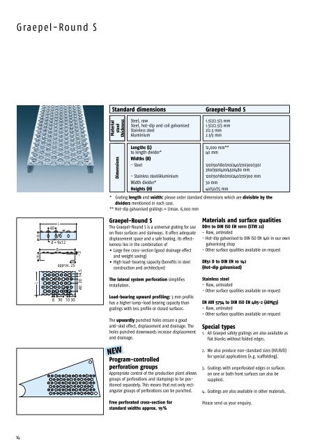
Graepel-Round S
Graepel-Round S
Graepel-Round S

You also want an ePaper? Increase the reach of your titles
YUMPU automatically turns print PDFs into web optimized ePapers that Google loves.
<strong>Graepel</strong>-<strong>Round</strong> S<br />
Standard dimensions<br />
<strong>Graepel</strong>-Rund S<br />
Material<br />
steel<br />
thickness<br />
Steel, raw<br />
Steel, hot-dip and coil galvanised<br />
Stainless steel<br />
Aluminium<br />
1.5/2/2.5/3 mm<br />
1.5/2/2.5/3 mm<br />
2/2.5 mm<br />
2.5/3 mm<br />
Dimensions<br />
Lengths (L)<br />
12,000 mm**<br />
to length divider*<br />
40 mm<br />
Widths (B)<br />
- Steel 120/150/180/210/240/270/300/330/<br />
360/390/420/450/480 mm<br />
- Stainless steel/Aluminium 120/150/180/210/240/270/300 mm<br />
Width divider*<br />
30 mm<br />
Heights (H)<br />
40/50/75 mm<br />
* Grating length and width: please order standard dimensions which are divisible by the<br />
dividers mentioned in each case.<br />
** Hot-dip galvanised gratings = L/max. 6,000 mm<br />
H<br />
H<br />
L<br />
L<br />
40<br />
Ø = 9x12<br />
B<br />
approx. 25<br />
8 30 10 30<br />
~3<br />
40 20 14.5<br />
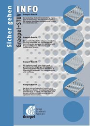
<strong>Graepel</strong>-<strong>Round</strong> S<br />
The <strong>Graepel</strong>-<strong>Round</strong> S is a universal grating for use<br />
on floor surfaces and stairways. It offers adequate<br />
displacement space and a safe footing. Its effectiveness<br />
lies in the combination of<br />
• Large free cross-section (good drainage effect<br />
and weight saving)<br />
•<br />
High load-bearing capacity (benefits in steel<br />
construction and architecture)<br />
The lateral system perforation simplifies<br />
installation.<br />
Load-bearing upward profiling: 3 mm profile<br />
has a higher lump-load bearing capacity than<br />
gratings with less profile or closed surfaces.<br />
The upwardly punched holes ensure a good<br />
anti-skid effect, displacement and drainage. The<br />
holes punched downwards increase displacement<br />
and drainage.<br />
NEW<br />
Program-controlled<br />
perforation groups<br />
Appropriate control of the production plant allows<br />
groups of perforations and stampings to be positioned<br />
separately. This means that not only rectangular<br />
groups of perforations can be punched.<br />
Materials and surface qualities<br />
DD11 to DIN ISO EN 10111 (STW 22)<br />
-Raw, untreated<br />
- Hot-dip galvanised to DIN ISO EN 1461 in our own<br />
galvanising shop<br />
- Other surface qualities available on request<br />
DX51 D to DIN EN 10 142<br />
(Hot-dip galvanised)<br />
Stainless steel<br />
-Raw, untreated<br />
- Other surface qualities available on request<br />
EN AW 5754 to DIN ISO EN 485-2 (AlMg3)<br />
-Raw, untreated<br />
- Other surface qualities available on request<br />
Special types<br />
1. All <strong>Graepel</strong> safety gratings are also available as<br />
flat blanks without folded edges.<br />
2. We also produce non-standard sizes (H/L/B/D)<br />
for special applications (e.g. scaffolding).<br />
3. Gratings with unperforated edges or surfaces<br />
on one or both front surfaces can also be<br />
supplied.<br />
4. Gratings are also available in other materials.<br />
Free perforated cross-section for<br />
standard widths approx. 19%<br />
Please send us your enquiry.<br />
14
<strong>Graepel</strong>-<strong>Round</strong> S<br />
Description<br />
Technical data<br />
Load values<br />
For notes on these tables, please see page 7<br />
Evenly<br />
distributed load<br />
Load F [in kN] for evenly distributed load<br />
(The figures apply for one single grating)<br />
H Mater- D Support length L/mm<br />
[mm] ial [mm] 500 750 1,000 1,250 1,500 1,750 2,000 2,250 2,500 2,750 3,000<br />
DD11 2.0 7.762 5.174 3.881 3.105 2.587 2.218 1.940 1.725 1.552 1.411 1.294<br />
(Stw 22) 2.5 9.337 6.225 4.669 3.735 3.112 2.668 2.334 2.075 1.867 1.698 1.556<br />
3.0 10.772 7.181 5.386 4.309 3.591 3.078 2.693 2.394 2.154 1.959 1.795<br />
40 EN AW 2.0 5.808 3.872 2.904 2.323 1.936 1.659 1.452 1.291 1.162 1.056 0.968<br />
5754 2.5 6.987 4.658 3.494 2.795 2.329 1.996 1.747 1.553 1.397 1.270 1.165<br />
(AlMg3) 3.0 8.061 5.374 4.030 3.224 2.687 2.303 2.015 1.791 1.612 1.466 1.343<br />
St. steel 2.0 6.864 4.576 3.432 2.746 2.288 1.961 1.716 1.525 1.373 1.248 1.144<br />
DD 11 2.0 10.678 7.119 5.339 4.271 3.559 3.051 2.670 2.373 2.136 1.941 1.780<br />
(Stw 22) 2.5 12.924 8.616 6.462 5.170 4.308 3.693 3.231 2.872 2.585 2.350 2.154<br />
3.0 15.018 10.012 7.509 6.007 5.006 4.291 3.754 3.337 3.004 2.730 2.503<br />
50 EN AW 2.0 7.990 5.327 3.995 3.196 2.663 2.283 1.998 1.776 1.598 1.453 1.332<br />
5754 2.5 9.671 6.447 4.836 3.868 3.224 2.763 2.418 2.149 1.934 1.758 1.612<br />
(AlMg3) 3.0 11.238 7.492 5.619 4.495 3.746 3.211 2.809 2.497 2.248 2.043 1.873<br />
St. steel 2.0 9.443 6.295 4.722 3.777 3.148 2.698 2.361 2.098 1.889 1.717 1.574<br />
DD 11 2.0 19.428 12.952 9.714 7.771 6.476 5.551 4.857 4.317 3.886 3.532 3.238<br />
Single load<br />
Load F [in kN] for single load<br />
(The figures apply for one single grating)<br />
Support length L/mm<br />
500 750 1,000 1,250 1,500 1,750 2,000 2,250 2,500 2,750 3,000<br />
4.851 2.985 2.156 1.687 1.386 1.176 1.021 0.903<br />
5.836 3.591 2.594 2.030 1.667 1.415 1.229 1.086 0.973<br />
6.733 4.143 2.992 2.342 1.924 1.632 1.417 1.253 1.122 1.016 0.929<br />
3.630 2.234 1.613 1.263 1.037 0.880<br />
4.367 2.687 1.941 1.519 1.248 1.059 0.919<br />
5.038 3.100 2.239 1.752 1.439 1.221 1.061 0.937<br />
4.290 2.640 1.907 1.492 1.226 1.040 0.903<br />
6.674 4.107 2.966 2.321 1.907 1.618 1.405 1.242 1.112 1.007 0.921<br />
8.078 4.971 3.590 2.810 2.308 1.958 1.701 1.503 1.346 1.219<br />
9.386 5.776 4.172 3.265 2.682 2.275 1.976 1.746 1.564 1.417 1.295<br />
4.994 3.073 2.220 1.737 1.427 1.211 1.051 0.929<br />
6.045 3.720 2.686 2.102 1.727 1.465 1.273 1.125 1.007 0.912<br />
7.024 4.322 3.122 2.443 2.007 1.703 1.479 1.307 1.171 1.060 0.969<br />
5.902 3.632 2.623 2.053 1.686 1.431 1.243 1.098 0.984<br />
12.142 7.472 5.397 4.223 3.469 2.944 2.556 2.259 2.024 1.833 1.675<br />
(Stw 22) 2.5 23.708 15.805 11.854 9.483 7.903 6.774 5.927 5.268 4.742 4.311 3.951 14.818 9.119 6.586 5.154 4.234 3.592 3.119 2.757 2.470 2.237 2.044<br />
3.0 27.765 18.510 13.883 11.106 9.255 7.933 6.941 6.170 5.553 5.048 4.628 17.353 10.679 7.713 6.036 4.958 4.207 3.653 3.229 2.892 2.619 2.394<br />
75 EN AW 2.0 14.538 9.692 7.269 5.815 4.846 4.154 3.634 3.231 2.908 2.643 2.423 9.086 5.591 4.038 3.160 2.596 2.203 1.913 1.690 1.514 1.371 1.253<br />
5754 2.5 17.741 11.827 8.870 7.096 5.914 5.069 4.435 3.942 3.548 3.226 2.957 11.088 6.823 4.928 3.857 3.168 2.688 2.334 2.063 1.848 1.674 1.529<br />
(AlMg3) 3.0 20.777 13.851 10.388 8.311 6.926 5.936 5.194 4.617 4.155 3.778 3.463 12.986 7.991 5.771 4.517 3.710 3.148 2.734 2.416 2.164 1.960 1.791<br />
St. steel 2.0 17.181 11.454 8.590 6.872 5.727 4.909 4.295 3.818 3.436 3.124 2.863 10.738 6.608 4.772 3.735 3.068 2.603 2.261 1.998 1.790 1.621 1.481<br />
Maximum possible lump load F [in kN]<br />
(The figures apply for DD11—StW 22)<br />
Grating width B<br />
Load area 200 x 200 mm<br />
[mm]<br />
Sheet thickness [mm]<br />
2.0 2.5 3.0<br />
120 3.04 4.05 5.22<br />
150 2.08 2.77 3.57<br />
180 1.54 2.05 2.64<br />
210 1.20 1.60 2.06<br />
240 1.00 1.33 1.71<br />
270 0.86 1.15 1.48<br />
300 0.77 1.03 1.32<br />
330 0.70 0.94 1.21<br />
360 0.65 0.87 1.12<br />
390 0.61 0.81 1.05<br />
420 0.58 0.77 0.99<br />
Lump load<br />
Conversion factors<br />
Table value x<br />
DD11 (StW 22) → stainless steel 0.85<br />
DD11 (StW 22) → EN AW 5754 (AlMg3) 0.75<br />
Note: The figures are calculated for gratings which are supported over their whole length. For a given<br />
span width, the values stated in this lump-load table must not exceed those given in the single-load<br />
table.<br />
Moments of inertia<br />
and section modulus<br />
Grating cross-sections (axis X-X 1 )<br />
H<br />
x<br />
B<br />
Fold Sheet Moment Minimum<br />
height thickness of inertia moment<br />
of resistance<br />
H D J x<br />
[mm] [mm] [mm 4 ] W x [mm 3 ]<br />
2.0 73 290. 3 300.<br />
40 2.5 88 170. 3 970.<br />
3.0 101 810. 4 580.<br />
2.0 124 820. 4 540.<br />
50 2.5 151 050. 5 495.<br />
3.0 175 470. 6 385.<br />
2.0 333 995. 8 260.<br />
75 2.5 407 610. 10 080.<br />
3.0 477 530. 11 805.<br />
x 1<br />
15