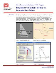
TRUNNION ANCHOR ROD FAILURES
TRUNNION ANCHOR ROD FAILURES
TRUNNION ANCHOR ROD FAILURES

Create successful ePaper yourself
Turn your PDF publications into a flip-book with our unique Google optimized e-Paper software.
MOBILE DISTRICT<br />
<strong>TRUNNION</strong> <strong>ANCHOR</strong> <strong>ROD</strong> <strong>FAILURES</strong><br />
<strong>TRUNNION</strong> <strong>ANCHOR</strong> <strong>ROD</strong> <strong>FAILURES</strong><br />
WEST POINT DAM PROJECT, GA.<br />
GA.<br />
RF HENRY LOCK AND DAM, AL<br />
APRIL 2009<br />
11 February 2011<br />
GEORGE V. POIROUX, P.E.<br />
Chief Geotech. Envir. & HTRW Branch<br />
DAVOOD GEORGE V. TASHBIN, POIROUX, P.E.<br />
P.E.<br />
Chief Geotech. Envir. & HTRW Branch<br />
Dam Safety Program Manager<br />
1
MOBILE DISTRICT<br />
JACKSON<br />
Okatibee<br />
Lake<br />
Stennis<br />
L&D<br />
Bevil<br />
L& D<br />
TN<br />
AL<br />
Jamie Whitten L&D<br />
G V “Sonny” Montgomery Lock<br />
John Rankin Lock<br />
Fulton Lock<br />
Glover Wilkins Lock<br />
Amory Lock<br />
Aberdeen<br />
L & D<br />
Heflin<br />
L & D<br />
Millers Ferry L & D<br />
GA<br />
MONTGOMERY<br />
Carters<br />
Lake Dam<br />
Allatoona<br />
Lake Dam<br />
John Hollis Bankhead L & D<br />
Holt L& D<br />
Oliver L & D<br />
A. I. Selden L & D West<br />
Demopolis<br />
L & D<br />
Coffeeville<br />
L & D<br />
R.F. Henry<br />
L&D<br />
Point<br />
Project<br />
Walter F.<br />
George<br />
L & D<br />
Buford<br />
Dam<br />
ATLANT<br />
A<br />
Indicates Project<br />
with Post-tensioned<br />
Anchor Rods<br />
LA<br />
Mobile<br />
Claiborne L & D<br />
Gulf of Mexico<br />
G. W. Andrews<br />
L &<br />
D<br />
Jim Woodruff<br />
L & D<br />
TALLAHASSEE<br />
FL<br />
MOBILE DISTRICT PROJECTS<br />
2
MOBILE DISTRICT<br />
DAM SAFETY ACTION CODE (DSAC)<br />
• R. F. HENRY: DSAC 3<br />
• WEST POINT DAM: DSAC 4 (April 2006 - Original Screening)<br />
DSAC 3 (Revised May 2008)<br />
3
MOBILE DISTRICT<br />
POST-TENSIONED TENSIONED <strong>TRUNNION</strong> <strong>ANCHOR</strong> TENDONS<br />
• Mandated Design by USACE HQ. (1960s)<br />
• COE Standard (EM 1110-2-2702)<br />
2702)<br />
• Adopted by other Government Agencies and Industry<br />
• Offered Advantages over Steel Beam/Girder Designs<br />
• Limited Suppliers<br />
• Rod Sensitivity<br />
• Inability for Inspection / Repair<br />
4
MOBILE DISTRICT<br />
TENDONS<br />
GROUP<br />
Figure 5-1<br />
EM1110-2-2702<br />
5
GRIP NUT ASSEMBLY<br />
MOBILE DISTRICT<br />
GRIP NUT<br />
BAR<br />
GRIP NUT<br />
GROUT HOLE<br />
DRY PLACED<br />
PLATE<br />
TAIL<br />
FLEXIBLE<br />
TUBING<br />
SLEEVE<br />
Howlett Grip Nut<br />
6
MOBILE DISTRICT<br />
<strong>TRUNNION</strong> GIRDER<br />
BASE PLATE<br />
GRIP NUT<br />
DEAD END<br />
<strong>ANCHOR</strong><br />
NUT<br />
<strong>TRUNNION</strong><br />
GIRDER<br />
CONC PIER<br />
TAIL<br />
FREE LENGTH<br />
7
MOBILE DISTRICT<br />
Access Challenges<br />
R.F. Henry Lock &<br />
Dam<br />
Near Selma, Alabama<br />
Const: 1968<br />
11 Spillway Gates<br />
42 trunnion rods per pier (462 total)<br />
Spillway Gate Trunnion Piers<br />
8
MOBILE DISTRICT<br />
Broken Trunnion Anchor<br />
Rods (protruding through<br />
cover plates)<br />
Pier #1<br />
Pier #8<br />
9
MOBILE DISTRICT<br />
Trunnion Rods at RF Henry Dam - Note short tail on rods<br />
Rods 1-1/4 “ diameter<br />
UTS is 145 ksi<br />
Post-Tensioned to 115.7k<br />
10
MOBILE DISTRICT<br />
WEST POINT DAM & POWERHOUSE<br />
(Near West Point, GA)<br />
11
WEST POINT PROJECT<br />
TAINTER GATE <strong>TRUNNION</strong>S<br />
(6 Gates – 5 Shared Piers with 2 End Blocks)<br />
Constructed 1969<br />
376 trunnion anchor rods<br />
MOBILE DISTRICT<br />
Pier 9<br />
Pier 10<br />
12
WEST POINT PROJECT<br />
MOBILE DISTRICT<br />
Pier 9 Pier #10 Trunnion Anchor Boxes<br />
West (10W) and East (10E)<br />
March 6, 2008<br />
Pier 10<br />
13
MOBILE DISTRICT<br />
West Point Dam<br />
Trunnion Rods with Cover Removed<br />
Note two rods missing.<br />
Rods 1-1/4” diameter<br />
UTS is 145 ksi<br />
Post-tensioned to 115.7k<br />
14
ACTIONS TAKEN<br />
MOBILE DISTRICT<br />
Visual Inspection of Cover Boxes on all 15 Projects<br />
within Mobile District<br />
Inspection Checklist was developed for each Project<br />
No issues observed at any other Project<br />
15
Structural Calculation of Factor of Safety<br />
Analysis used 106.7 kips as working load<br />
West Point Dam<br />
MOBILE DISTRICT<br />
Loss of 7 Rods within the 30 Rod Assembly FS approaches 1.00<br />
Loss of 5 Rods within the 30 Rod Assembly Decommission Gate<br />
RF Henry Lock and Dam<br />
ACTIONS TAKEN<br />
Loss of 4 Rods within the 21 Rod Assembly FS approaches 1.00<br />
Loss of 3 Rods within the 21 Rod Assembly Decommission Gate<br />
16
Video Bore Scope<br />
RF Henry<br />
Possibly 5 rods broken .<br />
Tails 1 to 3 inches long<br />
West Point<br />
MOBILE DISTRICT<br />
ACTIONS TAKEN Continued<br />
Boxes contained several inches of grease<br />
Boxes contained water - 12 inches in some boxes<br />
Possibly 7 rods broken – later confirmed that only 5 were broken<br />
Tails 28 to 30 inches long.<br />
17
MOBILE DISTRICT<br />
VIDEO BORE SCOPE RF HENRY DAM<br />
Trunnion Anchor Rods<br />
Powerhouse Pier Gate Pier Gate Pier Gate Pier Gate Pier Gate Pier Gate Pier Gate Pier Gate Pier Gate Pier Gate Pier Gate Pier East<br />
1 1 2 2 3 3 4 4 5 5 6 6 7 7 8 8 9 9 10 10 11 11 12<br />
Ab<br />
ut<br />
me<br />
nt<br />
West East West East West East West East West East West East West East West East West East West East West East West East<br />
C W C E W C E W C E W C E W C E W C E W C E W C E W C E W C E W C E W C E W C E W C E W C E W C E W C E W C E W C E W C E W C E W C E C<br />
Row 1 1 1 1 1 1 1 1 1 1 1 1 1 1 1 1 1 1 1 1 1 1 1 1 1 1 1 1 1 1 1 1 1 1 1 1 1 1 1 1 1 1 1 1 1 1 1 1 1 1 1 1 1 1 1 1 1 1 1 1 1 1 1 1 1 1 1 1 1<br />
Row 2 2 2 2 2 2 2 2 2 2 2 2 2 2 2 2 2 2 2 2 2 2 2 2 2 2 2 2 2 2 2 2 2 2 2 2 2 2 2 2 2 2 2 2 2 2 2 2 2 2 2 2 2 2 2 2 2 2 2 2 2 2 2 2 2 2 2 2 2<br />
Row 3 3 3 3 3 3 3 3 3 3 3 3 3 3 3 3 3 3 3 3 3 3 3 3 3 3 3 3 3 3 3 3 3 3 3 3 3 3 3 3 3 3 3 3 3 3 3 3 3 3 3 3 3 3 3 3 3 3 3 3 3 3 3 3 3 3 3 3 3<br />
Row 4 4 4 4 4 4 4 4 4 4 4 4 4 4 4 4 4 4 4 4 4 4 4 4 4 4 4 4 4 4 4 4 4 4 4 4 4 4 4 4 4 4 4 4 4 4 4 4 4 4 4 4 4 4 4 4 4 4 4 4 4 4 4 4 4 4 4 4<br />
Row 5 5 5 5 5 5 5 5 5 5 5 5 5 5 5 5 5 5 5 5 5 5 5 5 5 5 5 5 5 5 5 5 5 5 5 5 5 5 5 5 5 5 5 5 5 5 5 5 5 5 5 5 5 5 5 5 5 5 5 5 5 5 5 5 5 5 5 5 5<br />
Row 6 6 6 6 6 6 6 6 6 6 6 6 6 6 6 6 6 6 6 6 6 6 6 6 6 6 6 6 6 6 6 6 6 6 6 6 6 6 6 6 6 6 6 6 6 6 6 6 6 6 6 6 6 6 6 6 6 6 6 6 6 6 6 6 6 6 6 6<br />
Row 7 7 7 7 7 7 7 7 7 7 7 7 7 7 7 7 7 7 7 7 7 7 7 7 7 7 7 7 7 7 7 7 7 7 7 7 7 7 7 7 7 7 7 7 7 7 7 7 7 7 7 7 7 7 7 7 7 7 7 7 7 7 7 7 7 7 7 7 7<br />
W<br />
C<br />
West column in a specific<br />
group.<br />
Center column in a specific<br />
group.<br />
4<br />
Anchor Rod Tension estimated by FHD Dispersive Wave Technology<br />
Anchor Rod has been<br />
removed<br />
Anchor Rod broken in-place - to be remvoed and rod length to be<br />
measured<br />
E<br />
East column in a specific<br />
group.<br />
18
MOBILE DISTRICT<br />
Video Bore Scope WEST POINT Dam<br />
Trunnion Anchor Rod Video Inspection, March 2008<br />
Updated April 2008 as closer inspection revealed that 2 rods previously reported as failed, appear to be functioning as designed.<br />
(Pier 8, East group, west column, row 8 and Pier 10, West group, west column, row 3)<br />
BLOCK<br />
5<br />
Gate<br />
1<br />
PIER<br />
6<br />
Gate<br />
2<br />
PIER<br />
7<br />
Gate<br />
3<br />
PIER<br />
8<br />
Gate<br />
4<br />
PIER<br />
9<br />
Gate<br />
5<br />
PIER<br />
10<br />
Gate<br />
6<br />
BLOCK<br />
E<br />
West<br />
East<br />
West<br />
East<br />
West<br />
East<br />
West<br />
East<br />
West<br />
East<br />
West<br />
East<br />
West<br />
East<br />
W E<br />
W C E<br />
W C E W C E<br />
W C E W C E<br />
W C E W C E<br />
W C E W C E<br />
W C E W C E<br />
W C E W E<br />
1 1 1 1 1<br />
1 1 1 1 1 1<br />
1 1 1 1 1 1<br />
1 1 1 1 1 1<br />
1 1 1 1 1 1<br />
1 1 1 1 1 1<br />
1 1 1 1 1<br />
2 2 2 2 2<br />
2 2 2 2 2 2<br />
2 2 2 2 2 2<br />
2 2 2 2 2 2<br />
2 2 2 2 2 2<br />
2 2 2 2 2 2<br />
2 2 2 2 2<br />
3 3 3 3 3<br />
3 3 3 3 3 3<br />
3 3 3 3 3 3<br />
3 3 3 3 3 3<br />
3 3 3 3 3 3<br />
3 3 3 3 3 3<br />
3 3 3 3 3<br />
4 4 4 4 4<br />
4 4 4 4 4 4<br />
4 4 4 4 4 4<br />
4 4 4 4 4 4<br />
4 4 4 4 4 4<br />
4 4 4 4 4 4<br />
4 4 4 4 4<br />
5 5 5<br />
5 5 5 5 5 5<br />
5 5 5 5 5 5<br />
5 5 5 5 5 5<br />
5 5 5 5 5 5<br />
5 5 5 5 5 5<br />
5 5 5<br />
6 6 6<br />
6 6 6 6 6 6<br />
6 6 6 6 6 6<br />
6 6 6 6 6 6<br />
6 6 6 6 6 6<br />
6 6 6 6 6 6<br />
6 6 6<br />
7 7 7<br />
7 7 7 7 7 7<br />
7 7 7 7 7 7<br />
7 7 7 7 7 7<br />
7 7 7 7 7 7<br />
7 7 7 7 7 7<br />
7 7 7<br />
8 8 8<br />
8 8 8 8 8 8<br />
8 8 8 8 8 8<br />
8 8 8 8 8 8<br />
8 8 8 8 8 8<br />
8 8 8 8 8 8<br />
8 8 8<br />
9 9 9<br />
9 9 9 9 9 9<br />
9 9 9 9 9 9<br />
10 10 10 10 10 10 10 10 10 Pier 9<br />
10 10 10 10 10 10<br />
9 9 9 9 9 9<br />
10 10 10 10 10 10<br />
9 9 9 9 9 9<br />
10 10 10 10 10 10<br />
9 9 9 9 9 9<br />
10 10 10 10 10 10<br />
9 9 9<br />
10 10 10<br />
W West column in a specific group<br />
C Center column in a specific group<br />
E East column in a specific group<br />
NOTE: In every instance of a failed rod, there was some visual indication on the trunnion<br />
anchor assembly metal cover boxes that a release had occurred.<br />
# Anchor Rod has failed.<br />
# Anchor Rod appears to be functioning as designed.<br />
19
MOBILE DISTRICT<br />
ACTIONS TAKEN Continued<br />
Extracted All Released Rods (5 Total) at West Point Dam<br />
Measured Lengths<br />
Retained rod and grip nuts<br />
Cut rods in 24 to 36 inches pieces to assist handling<br />
Extracted 4 Released Rods at RF Henry Dam<br />
Measured Lengths<br />
Retained rod and grip nuts<br />
Performed Metallurgical Testing<br />
20
BASE<br />
PLATE<br />
R.F. HENRY DAM<br />
MOBILE DISTRICT<br />
DEAD END<br />
<strong>ANCHOR</strong><br />
<strong>ROD</strong> P1WC6 (BROKE 2006)<br />
12’6”<br />
<strong>ROD</strong> P1WC7 (BROKE 2010)<br />
25’6”<br />
<strong>ROD</strong> P8WW3 (BROKE 2006)<br />
<strong>ROD</strong> P8WW4 (BROKE 1994)<br />
0’<br />
10’ 20’ 30’ 40’<br />
21
BASE<br />
PLATE<br />
WEST POINT DAM<br />
MOBILE DISTRICT<br />
<strong>ROD</strong> B5EE6 (BREAK DISCOVERED 2008)<br />
5’ – ½”<br />
DEAD END<br />
<strong>ANCHOR</strong><br />
<strong>ROD</strong> P10WW2 (BREAK DISCOVERED 2008)<br />
4’ – 1”<br />
<strong>ROD</strong> P10EC2 (BREAK DISCOVERED 2008)<br />
15’<br />
<strong>ROD</strong> P10EE10 (BREAK DISCOVERED 2008)<br />
5’ – 8”<br />
<strong>ROD</strong> BEEE3 (BREAK DISCOVERED 2008)<br />
11’ – 3”<br />
0’<br />
10’ 20’ 30’ 40’<br />
22
MOBILE DISTRICT<br />
<strong>TRUNNION</strong> <strong>ANCHOR</strong> <strong>ROD</strong> LAB ANALYSIS<br />
1. Magnetic Particle Test<br />
‒ No cracks or discontinuities observed except on rod<br />
P1WC7 at RF Henry . All failures were similar in<br />
nature.<br />
2. Chemical Analysis<br />
‒ Material similar to AISI 5160<br />
3. Microscopic Test<br />
‒ Fractures had distinct origins. Flat fracture surface.<br />
No evidence of fatigue. No rod deformation.<br />
4. Charpy and Bend Test<br />
‒ Material has little toughness and high notch sensitivity<br />
Failure Mode – Brittle Failure<br />
“Prediction of Brittle Failure in notch sensitive materials is difficult.<br />
fficult.”<br />
23
MOBILE DISTRICT<br />
WEST POINT <strong>ANCHOR</strong> <strong>ROD</strong>S<br />
This photograph shows Sample #2 in the ‘as<br />
received’ condition. The blue arrow indicates the<br />
fracture origin and the white arrows indicate the<br />
crack propagation direction. Note the area circled<br />
in green appears to have been a pre-existing existing crack<br />
which is more heavily oxidized than the rest of<br />
the fracture surface.<br />
This photograph shows Sample #2 with no visible<br />
“necking” of the bar near the fracture as would be<br />
seen with a ductile failure.<br />
24
MOBILE DISTRICT<br />
Stress Corrosion Crack<br />
RF Henry Rod P1 W C 7<br />
25
MOBILE DISTRICT<br />
RF Henry Rod P8 W W3<br />
26
MOBILE DISTRICT<br />
ACTIONS TAKEN continued<br />
Engineering Forensics<br />
TYPE: Brittle Failure<br />
Notch Sensitive<br />
NATURE:<br />
Surface defect<br />
Manufacturing defect which caused stress riser<br />
CAUSE:<br />
Age –Hydrogen /Calcium<br />
Vibration of spillway gate at higher gate openings<br />
Corrosion – due to moisture and loss of corrosion inhibitor<br />
contributor<br />
PREDICTABILITY OF FAILURE: Failure is not Predictable<br />
27
MOBILE DISTRICT<br />
ACTIONS TAKEN continued<br />
Modified All Cover Boxes to Enable Visual Inspection & Testing<br />
Installed Accelerometers for Continuous Monitoring<br />
Placed collar on rod tail exactly 1 inch from grip nut<br />
28
WEST POINT PROJECT<br />
MOBILE DISTRICT<br />
Modified cover boxes for all piers<br />
Pier 9<br />
Pier 10<br />
29
WEST POINT PROJECT<br />
MOBILE DISTRICT<br />
Modified cover boxes<br />
Pier 9<br />
Pier 10<br />
30
MOBILE DISTRICT<br />
• RF Henry New Trunnion Rod Cover Box<br />
31
MOBILE DISTRICT<br />
ACTIONS TAKEN continued<br />
Ultrasonic Testing by ERDC-CERL<br />
CERL<br />
Non Destructive Test ( NDT) Measure Tension in Each Rod Block E<br />
East (30 Rods) and West (7 Rods) at West Point Dam<br />
Dispersive Bending Wave NDT by FDH, Engineering<br />
Tested Rods in Block E – Static and Dynamic Condition at West Point<br />
32
MOBILE DISTRICT<br />
ULTRASONIC<br />
TESTING<br />
(by ERDC-<br />
CERL)<br />
April 2008<br />
33
MOBILE DISTRICT<br />
MOBILE DISTRICT<br />
34<br />
ULTRASONIC TEST RESULTS AS % OF AS-BUILTS<br />
120<br />
100<br />
80<br />
60<br />
40<br />
20<br />
0<br />
ww1<br />
ww3<br />
ww5<br />
ww7<br />
ww9<br />
wc1<br />
wc3<br />
wc5<br />
wc7<br />
wc9<br />
we1<br />
we3<br />
we5<br />
we7<br />
we9<br />
ew1<br />
ew3<br />
ee1<br />
ee3<br />
%of % As-Builts of As-Builts<br />
Ultrasonic Test % of As Built
MOBILE DISTRICT<br />
DISPERSIVE BENDING WAVE TEST<br />
by FDH April 2009<br />
35
MOBILE DISTRICT<br />
MOBILE DISTRICT<br />
DISPERSIVE WAVE RESULTS AS % OF AS-BUILTS<br />
120<br />
100<br />
36<br />
80<br />
60<br />
%of % As-Built of As-Builts<br />
40<br />
20<br />
0<br />
ww1<br />
ww3<br />
ww5<br />
ww7<br />
ww9<br />
wc1<br />
wc3<br />
wc5<br />
wc7<br />
wc9<br />
we1<br />
we3<br />
we5<br />
we7<br />
we9<br />
ew1<br />
ew3<br />
ee1<br />
ee3<br />
Dispersive Wave % of As Built
MOBILE DISTRICT<br />
ACTIONS TAKEN continued<br />
PROCURING AN ADDITIONAL SET OF SPILLWAY<br />
STOPLOGS FOR RF HENRY AND WEST POINT DAMS<br />
Decommission two gates if needed<br />
PREPARING RESTRICTED RESEVIOR OPERATIONS PLAN<br />
FOR RF HENRY AND WEST POINT DAMS<br />
Water Management Plan for loss of two spillway gates<br />
37
MOBILE DISTRICT<br />
ACTIONS TAKEN continued<br />
PDT performed site inspection and review of As-Built<br />
Documents<br />
A-E E Prepared Recommendation Report<br />
Preliminary estimate of tension in each rod by Dispersive Wave<br />
Technology<br />
Site Inspections and analysis<br />
COE and Industry input/solutions<br />
Partner with Industry for Lift-Off Testing<br />
Preliminary Design Solutions<br />
The Path Forward<br />
38
MOBILE DISTRICT<br />
THE PATH FORWARD<br />
FOR<br />
RF Henry Lock and Dam<br />
And<br />
West Point Dam<br />
39
MOBILE DISTRICT<br />
Perform Quality Control Check on Lift-Off Procedures<br />
Testing at Mock-up Pier at FDH<br />
Simulate as-built conditions – Various tensions, tail lengths<br />
Perform test on actual rod and grip nut from West Point Dam<br />
Evaluate Processes and results. Define what constitutes lift-off<br />
Document and incorporate Lessons Learned prior to field testing<br />
Perform Lift-Off Test<br />
The Path Forward<br />
68 Rods at West Point (added 40 more rods as mod for total of 108)<br />
98 Rods at RF Henry (added 10 more rods as mod for total of 108)<br />
Rods were selected<br />
Obtain Dispersive Wave Tension (DWT) Datasets prior to<br />
and after each lift-off test<br />
40
MOBILE DISTRICT<br />
The Path Forward Continued<br />
Re-tension rods to 106 kips if lift-off is less than 100kips<br />
Re-tension three rods at each project to 115kips<br />
Reuse grip nuts- Original nuts produced by Howlett Machine<br />
(Calif.)<br />
Howlett Machine, (Calif.) contacted but would not sell or give these grip nuts to<br />
SAM. They did say that these nuts can be reused on the bar size designed for.<br />
Extract broken rods<br />
Carefully measure extracted rod lengths and record<br />
Photo broken ends<br />
Retrieve grip nuts from extracted rods, clean-up and store<br />
41
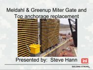
Working Platforms at each Trunnion Girder<br />
Certified and inspected<br />
Used by PDT<br />
MOBILE DISTRICT<br />
The Path Forward Continued<br />
Water Management thru Spillway Gates while work is<br />
being performed<br />
Close gates while work is being performed if possible<br />
Replace trunnion rod cover boxes at RF Henry<br />
Cut old boxes off<br />
Bolt on new box –must be waterproof<br />
Provide access hatch on top of box<br />
42
MOBILE DISTRICT<br />
The Path Forward Continued<br />
Validation of Dispersive Wave Tension Estimates<br />
Compare to actual lift-off load<br />
Develop equivalency equations<br />
Level of Confidence with DWT<br />
Estimate of tension in each rod at West Point and RF Henry<br />
COE to re-evaluate Factor of Safety for each Spillway Gate<br />
Original design provided SF 1.25<br />
43
Table 32: FDH NDT Average Load<br />
MOBILE DISTRICT<br />
Average Load<br />
Kip<br />
120.000<br />
100.000<br />
80.000<br />
60.000<br />
40.000<br />
20.000<br />
Strain Gauge<br />
PSI Gauge<br />
Load Cell<br />
FDH NDT<br />
0.000<br />
1 2 3<br />
Test<br />
Average Load (Kip)<br />
Test Strain Gauge PSI Gauge Load Cell FDH NDT<br />
1 51.220 59.521 56.687 55.908<br />
2 67.088 77.930 74.033 70.065<br />
3 85.167 96.689 92.173 92.978<br />
Test Strain Gauge PSI Gauge Load Cell FDH NDT<br />
1 53.860 59.442 58.220 56.906<br />
2 71.906 78.684 78.930 71.644<br />
3 98.506 106.107 105.400 106.132<br />
TT<br />
Test 1<br />
Test 2<br />
Mock-Up Tests at FDH Engineering<br />
44
MOBILE DISTRICT<br />
RRF Henry Dam<br />
Trunnion Rods<br />
45
MOBILE DISTRICT<br />
• West Point Dam trunnion rods to be lift-off<br />
tested<br />
West Point Dam, Georgia<br />
Post-Tensioned Trunnion Anchor Rods<br />
Lift-off Test Schedule<br />
Block Gate Pier Gate Pier Gate Pier Gate Pier Gate Pier Gate Block<br />
5 1 6 2 7 3 8 4 9 5 10 6 E<br />
West East West East West East West East West East West East West East<br />
W C E W C E W C E W C E W C E W C E W C E W C E W C E W C E W C E W C E W C E W C E<br />
1 1 1 1 1 1 1 1 1 1 1 1 1 1 1 1 1 1 1 1 1 1 1 1 1 1 1 1 1 1 1 1 1 1 1 1 1 1 1 1<br />
2 2 2 2 2 2 2 2 2 2 2 2 2 2 2 2 2 2 2 2 2 2 2 2 2 2 2 2 2 2 2 2 2 2 2 2 2 2<br />
3 3 3 3 3 3 3 3 3 3 3 3 3 3 3 3 3 3 3 3 3 3 3 3 3 3 3 3 3 3 3 3 3 3 3 3 3 3 3 3<br />
4 4 4 4 4 4 4 4 4 4 4 4 4 4 4 4 4 4 4 4 4 4 4 4 4 4 4 4 4 4 4 4 4 4 4 4 4 4 4<br />
5 5 5 5 5 5 5 5 5 5 5 5 5 5 5 5 5 5 5 5 5 5 5 5 5 5 5 5 5 5 5 5 5 5 5 5<br />
6 6 6 6 6 6 6 6 6 6 6 6 6 6 6 6 6 6 6 6 6 6 6 6 6 6 6 6 6 6 6 6 6 6 6<br />
7 7 7 7 7 7 7 7 7 7 7 7 7 7 7 7 7 7 7 7 7 7 7 7 7 7 7 7 7 7 7 7 7 7 7 7<br />
8 8 8 8 8 8 8 8 8 8 8 8 8 8 8 8 8 8 8 8 8 8 8 8 8 8 8 8 8 8 8 8 8 8 8 8<br />
9 9 9 9 9 9 9 9 9 9 9 9 9 9 9 9 9 9 9 9 9 9 9 9 9 9 9 9 9 9 9 9 9 9 9 9<br />
10 10 10 10 10 10 10 10 10 10 10 10 10 10 10 10 10 10 10 10 10 10 10 10 10 10 10 10 10 10 10 10 10 10 10<br />
Anchor Rod has failed<br />
Scheduled Lift-off Test<br />
46
MOBILE DISTRICT<br />
• R.F. Henry Dam trunnion rods to be lift-off<br />
tested<br />
Powerhouse Pier Gate Pier Gate Pier Gate Pier Gate Pier Gate Pier Gate Pier Gate Pier Gate Pier Gate Pier Gate Pier Gate Pier East<br />
1 1 2 2 3 3 4 4 5 5 6 6 7 7 8 8 9 9 10 10 11 11 12 Abutment<br />
West East West East West East West East West East West East West East West East West East West East West East West East<br />
C W C E W C E W C E W C E W C E W C E W C E W C E W C E W C E W C E W C E W C E W C E W C E W C E W C E W C E W C E W C E W C E W C E C<br />
Row 1 1 1 1 1 1 1 1 1 1 1 1 1 1 1 1 1 1 1 1 1 1 1 1 1 1 1 1 1 1 1 1 1 1 1 1 1 1 1 1 1 1 1 1 1 1 1 1 1 1 1 1 1 1 1 1 1 1 1 1 1 1 1 1 1 1 1 1 1<br />
Row 2 2 2 2 2 2 2 2 2 2 2 2 2 2 2 2 2 2 2 2 2 2 2 2 2 2 2 2 2 2 2 2 2 2 2 2 2 2 2 2 2 2 2 2 2 2 2 2 2 2 2 2 2 2 2 2 2 2 2 2 2 2 2 2 2 2 2 2 2<br />
Row 3 3 3 3 3 3 3 3 3 3 3 3 3 3 3 3 3 3 3 3 3 3 3 3 3 3 3 3 3 3 3 3 3 3 3 3 3 3 3 3 3 3 3 3 3 3 3 3 3 3 3 3 3 3 3 3 3 3 3 3 3 3 3 3 3 3 3 3 3<br />
Row 4 4 4 4 4 4 4 4 4 4 4 4 4 4 4 4 4 4 4 4 4 4 4 4 4 4 4 4 4 4 4 4 4 4 4 4 4 4 4 4 4 4 4 4 4 4 4 4 4 4 4 4 4 4 4 4 4 4 4 4 4 4 4 4 4 4 4 4<br />
Row 5 5 5 5 5 5 5 5 5 5 5 5 5 5 5 5 5 5 5 5 5 5 5 5 5 5 5 5 5 5 5 5 5 5 5 5 5 5 5 5 5 5 5 5 5 5 5 5 5 5 5 5 5 5 5 5 5 5 5 5 5 5 5 5 5 5 5 5 5<br />
Row 6 6 6 6 6 6 6 6 6 6 6 6 6 6 6 6 6 6 6 6 6 6 6 6 6 6 6 6 6 6 6 6 6 6 6 6 6 6 6 6 6 6 6 6 6 6 6 6 6 6 6 6 6 6 6 6 6 6 6 6 6 6 6 6 6 6 6 6<br />
Row 7 7 7 7 7 7 7 7 7 7 7 7 7 7 7 7 7 7 7 7 7 7 7 7 7 7 7 7 7 7 7 7 7 7 7 7 7 7 7 7 7 7 7 7 7 7 7 7 7 7 7 7 7 7 7 7 7 7 7 7 7 7 7 7 7 7 7 7 7<br />
# of Tests 1 7 8 7 6 4 4 4 4 5 4 5 4 4 2 7 4 4 5 5 3 5 3 2 107<br />
Anchor Rods To be Lift-Off Tested (Revised 6 Dec 2010)<br />
W West column in a specific group. Anchor Rod has been removed<br />
C Center column in a specific group. 4 Anchor Rod broken in-place - to be removed and rod length to be measured<br />
E East column in a specific group.<br />
2 Proposed lift-off test location 2 Rod to be retensioned to 60kips<br />
Revision: Rod P1 W C7 failed 1 Nov 2010. Extracted 12'-6' long on 17 Nov 2010.<br />
Rod P8 WW3 Extracted 32'-6' long on 12 Jan 2011.<br />
47
Rods<br />
Lift‐off Pressure<br />
Gauge (psi)<br />
Lift‐off Force<br />
Load cell<br />
(kips)<br />
Lift‐off Force<br />
Gauge (kips)<br />
Use Larger Lift‐off<br />
Force (kips)<br />
WEST POINT DAM LIFT OFF RECORD<br />
FDH Estimated<br />
Tension (kips)<br />
Rods<br />
Lift‐off Pressure<br />
Gauge (psi)<br />
MOBILE DISTRICT<br />
Lift‐off Force<br />
Load cell (kips)<br />
Lift‐off Force Gauge<br />
(kips)<br />
Use Larger Lift‐off<br />
Force (kips)<br />
B 5 WE 3 5100 ‐ 106.7 NLO 120+ P 8 EW 1 5190 110 108.6 NLO 120+<br />
B 5 EW 2 5100 ‐ 106.7 NLO 120+ P 8 EW 8 5100 107.3 106.7 NLO 120+<br />
B 5 EW 6 5100 108.26 106.7 NLO 120+ P 8 EE 3 5100 108.3. 106.7 NLO 120+<br />
B 5 EC 3 5130 110.19 107.4 NLO 120+ P 9 WW 4 5100 106.7 106.7 NLO 120+<br />
B 5 EC 5 5100 109.6 106.7 NLO 96.7 P 9 WW 9 5100 107.22 106.7 NLO 120+<br />
B 5 EC 7 5100 110.2 106.7 NLO 120+ P 9 WC 7 5100 106.72 106.7 NLO 120+<br />
B 5 EC 10 5100 108.3 106.7 NLO 120+ P 9 WC 9 5100 105.98 106.7 NLO 120+<br />
P 6 WW 6 5130 108.47 107.4 NLO 114.4 P 9 WE 2 5100 106.6 106.7 NLO 120+<br />
P 6 WC 2 5120 108.2 107.1 NLO 120+ P 9 WE 5 5100 106.6 106.7 NLO 120+<br />
P 6 WC 5 5120 108.8 107.1 NLO 120+ P 9 EW 2 5100 107.2 106.7 NLO 120+<br />
P 6 WC 6 5130 108.85 107.4 NLO 120+ P 9 EW 5 5100 107.39 106.7 NLO 120+<br />
P 6 WC 10 5140 108.85 107.6 NLO 120+ P 9 EE 2 5100 109.63 106.7 NLO 120+<br />
P 6 WE 8 5100 108.3 106.7 NLO 120+ P 9 EE 4 5100 107.73 106.7 NLO 120+<br />
P 6 EW 4 5250 110.1 109.9 NLO 120+ P 10 WC 3 5100 109.18 106.7 NLO 120+<br />
P 6 EC 4 5208 109.48 109.0 NLO 120+ P 10 WC 8 5100 109.79 106.7 NLO 120+<br />
P 6 EC 8 5184 109.1 108.5 NLO 120+ P 10 WE 1 5100 108.74 106.7 NLO 120+<br />
P 6 EE 2 5120 108.76 107.1 NLO 114.6 P 10 WE 9 5016 110 105.0 NLO 120+<br />
P7 WW 1 5419 115.7 113.4 NLO 120+ B E WW 1 5544 115.7 116.1 NLO 106.6<br />
P7 WW 2 5100 108.98 106.7 NLO 103.8 B E WW 2 5241 111.56 109.7 LO 100.1<br />
P7 WW 4 5100 108.9 106.7 NLO 120+ B E WW 3 5449 115.7 114.1 NLO 120+<br />
P7 WW 5 5100 108.39 106.7 NLO 101.7 B E WW 4 5436 115.7 113.8 NLO 120+<br />
P7 WW 6 5459 1115.7 114.3 NLO 98.4 B E WW 5 5452 115.7 114.1 NLO 120+<br />
P7 WW 9 5425 115.7 113.6 NLO 109.1 B E WW 6 5267 112.7 110.2 LO 116.8<br />
P7 WW 10 5100 107.97 106.7 NLO 107.8 B E WW 7 5471 115.7 114.5 NLO 120+<br />
P7 WC 1 5100 108 106.7 NLO 120+ B E WW 8 5409 115.7 113.2 NLO 120+<br />
P7 WC 2 5100 109.5 106.7 NLO 120+ B E WW 9 5328 115.7 111.5 NLO 110.9<br />
P7 WC 3 5100 108.01 106.7 NLO 120+ B E WW 10 5286 115.7 110.6 NLO 100.5<br />
P7 WC 5 5100 109.8 106.7 NLO 117.8 B E WC 1 5457 115.7 114.2 NLO 96.8<br />
P7 WC 6 5100 107.21 106.7 NLO 120+ B E WC 2 5427 115.7 113.6 NLO 111.1<br />
P7 WC 7 5100 107.76 106.7 NLO 120+ B E WC 3 5407 115.7 113.2 NLO 120+<br />
P7 WC 8 5370 115.7 112.4 NLO 120+ B E WC 4 5391 115.7 112.8 NLO 102.7<br />
P7 WE 9 5100 107.75 106.7 NLO 120+ B E WC 5 5470 115.7 114.5 NLO 120+<br />
P7 EW 9 5100 108.26 106.7 NLO 120+ B E WC 6 5330 112.48 111.6 LO 98.1<br />
P7 EW 10 5100 108.93 106.7 NLO 120+ B E WC 7 5444 115.7 114.0 NLO 120+<br />
P7 EC 1 5100 108.7 106.7 NLO 120+ B E WC 8 5249 112.26 109.9 NLO 120+<br />
P7 EC 3 5100 107.58 106.7 NLO 120+ B E WC 9 5440 115.7 113.9 LO 120+<br />
P7 EC 4 5400 108.7 113.0 NLO 120+ B E WC 10 5326 115.7 111.5 NLO 107.5<br />
P7 EC 6 5400 115.7 113.0 NLO 120+ B E WE 1 5482 115.7 114.8 NLO 120+<br />
P7 EC 8 5100 108.17 106.7 NLO 120+ B E WE 2 5324 112.88 111.4 LO 98.2<br />
P7 EC 10 5100 109 106.7 NLO 120+ B E WE 3 5449 115.7 114.1 NLO 120+<br />
P7 EE 1 5428 115.7 113.6 NLO 120+ B E WE 4 5300 110.2 110.9 LO 120+<br />
P7 EE 2 5375 114.16 112.5 NLO 120+ B E WE 5 5440 115.7 113.9 NLO 120+<br />
P7 EE 5 5100 108.52 106.7 NLO 120+ B E WE 6 5367 115.7 112.3 NLO 120+<br />
P7 EE 6 5400 115.7 113.0 NLO 120+ B E WE 7 5395 115.7 112.9 NLO 91.4<br />
P7 EE 8 5100 107.69 106.7 NLO 120+ B E WE 8 5362 113.7 112.2 LO 88.3<br />
P7 EE 9 5400 115.7 113.0 NLO 112.6 B E WE 9 5459 115.7 114.3 NLO 120+<br />
P7 EE 10 5438 115.7 113.8 NLO 120+ B E WE 10 5361 115.7 112.2 NLO 104.3<br />
P 8 WW 1 5308 115.7 111.1 NLO 97.0 B E EW 1 5378 115.7 112.6 NLO 120+<br />
P 8 WW 4 5413 115.7 113.3 NLO 120+ B E EW 2 5396 115.7 112.9 NLO 120+<br />
P 8 WW 7 5436 115.7 113.8 NLO 120+ B E EW 3 5319 115.7 111.3 NLO 112.2<br />
P 8 WW 9 5412 115.7 113.3 NLO 89.1 B E EW 4 5365 115.7 112.3 NLO 118.7<br />
P 8 WC 3 5070 110 106.1 NLO 120+ B E EC 1 5322 115.7 111.4 NLO 120+<br />
P 8 WE 3 5100 109.87 106.7 NLO 118.3 B E EC 2 5438 115.7 113.8 NLO 120+<br />
P 8 WE 4 5100 108.28 106.7 NLO 112.9 B E EC 3 5407 115.7 113.2 NLO 116.3<br />
P 8 WE 9 5500 117.4 115.1 NLO 120+<br />
FDH Estimated<br />
Tension (kips)<br />
48
Rod<br />
Recorded Lift‐off<br />
Pressure Gauge (psi)<br />
Actual Lift‐off Force<br />
Load cell (kips)<br />
Ram Lift‐off Force<br />
Pressure x Area (kips)<br />
LO = Lift Off<br />
NOL = No Lift<br />
Off<br />
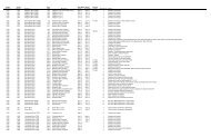
RF HENRY DAM LIFT OFF RECORD<br />
FDH Est.<br />
Tension (kips)*<br />
Rod<br />
Recorded Lift‐off<br />
Pressure Gauge (psi)<br />
Actual Lift‐off Force<br />
Load cell (kips)<br />
Ram Lift‐off Force<br />
Pressure x Area (kips)<br />
LO = Lift Off<br />
NOL = No Lift Off<br />
Pier 1 WC 5 5123 106.7 107.2 NLO 107.5 Pier 6 EW 6 5380 113.6 112.6 LO 105.1<br />
Pier 1 WC 5 5123 106.7 107.2 NLO 107.5 Pier 6 EW 7 5247 110.6 109.8 LO 101.3<br />
Pier 1 EW 1 5493 115 115.0 LO 108.0 Pier 6 EC 1 104.7<br />
Pier 1 EW 4 4908 101.9 102.7 LO 110.4 Pier 6 EC 6 5127 108.4 107.3 LO 101.9<br />
Pier 1 EC 1 4908 102 102.7 LO 109.4 Pier 6 EE 1 5265 112.4 110.2 LO 103.7<br />
Pier 1 EC 7 5448 112.4 114.0 LO 108.1 Pier 6 EE 3 5263 111.7 110.2 LO 106.6<br />
Pier 1 EE 3 5448 112.35 114.0 LO 107.7 Pier 7 WW 3 5112 108.6 107.0 LO 103.0<br />
Pier 1 EE 4 5493 115.7 115.0 NLO 108.6 Pier 7 WE 1 5215 110.6 109.1 LO 104.0<br />
Pier 1 EE 7 5494 115.7 115.0 NLO 106.2 Pier 7 WE 3 5153 109.6 107.8 LO 100.2<br />
Pier 2 WW 1 5450 115.7 114.1 NLO 111.0 Pier 7 WE 6 5268 111.9 110.3 LO<br />
Pier 2 WW 4 5337 112 111.7 LO 107.9 Pier 7 EW 6 5392 115.7 112.9 NLO 106.4<br />
Pier 2 WW 7 5595 115.4 117.1 LO 105.4 Pier 7 EW 7 5350 115.7 112.0 LO 105.3<br />
Pier 2 WC 1 5337 113.98 111.7 LO 107.0 Pier 7 EC 3 5310 113.4 111.1 NLO 100.7<br />
Pier 2 WC 7 5595 115.7 117.1 NLO 107.6 Pier 7 EE 7 5212 111.8 109.1 104.0<br />
Pier 2 WE 2 5444 115.7 114.0 NLO 109.3 Pier 8 WW 3 No load 114.2<br />
Pier 2 WE 3 5360 114.6 112.2 LO 108.4 Pier 8 WE 4 5500 N/A 115.1 NLO 108.6<br />
Pier 2 WE 4 5295 112.6 110.8 LO 108.5 Pier 8 WE 7 5200 N/A 108.8 LO 94.3<br />
Pier 2 EW 1 115.7 NLO 109.1 Pier 8 EW 2 5406 115.7 113.2 NLO 104.1<br />
Pier 2 EW 4 35 NLO 0.0* Pier 8 EW 3 4186 87.2 87.5 LO 102.7<br />
Pier 2 EW 7 110 NLO 105.5 Pier 8 EW 6 5406 115.7 113.2 NLO 103.3<br />
Pier 2 EC 6 115.7 110.0 NLO 109.6 Pier 8 EE 2 5406 115.7 113.2 NLO 104.1<br />
Pier 2 EC 7 104 NLO 108.7 Pier 8 EE 5 4960 106 103.8 LO 100.8<br />
Pier 2 EE 4 1700 35.2 35.3 0.0* Pier 8 EE 6 5440 115.7 113.9 NLO 105.9<br />
Pier 2 EE 7 107.0 105.7 Pier 8 EE 7 5140 109.6 107.6 LO 102.4<br />
Pier 3 WW 2 5014 106.3 104.9 LO 97.8 Pier 9 WW 2 5366 115.7 112.3 LO 105.6<br />
Pier 3 WW 3 4903 104.7 102.6 LO 98.6 Pier 9 WW 7 5278 112.8 110.5 LO 103.8<br />
Pier 3 WW 4 4990 105.6 104.4 LO 102.7 Pier 9 WE 4 5400 115.7 113.0 NLO 104.9<br />
Pier 3 WW 7 4903 104.6 102.6 LO 100.2 Pier 9 WE 5 5266 113.3 110.2 LO 104.2<br />
Pier 3 WC 5 4903 104.7 102.6 LO 96.7 Pier 9 EW 7 5014 107.6 104.9 LO 102.2<br />
Pier 3 WE 4 5320 112.7 111.3 LO 101.3 Pier 9 EE 1 5102 109/8 106.8 LO 103.9<br />
Pier 3 EW 4 98.6 111.6 LO 106.9 Pier 9 EE 4 5430 115.7 113.7 NLO 105.6<br />
Pier 3 EW 5 4902 104.2 102.6 NLO 97.9 Pier 9 EE 6 5230 111.9 109.5 LO 103.7<br />
Pier 3 EW 6 5265 107.4 110.2 NLO 99.8 Pier 10 WW 4 5325 112.4 111.5 LO 104.7<br />
Pier 3 EE 1 5087 109.2 106.5 LO 101.7 Pier 10 WW 5 5325 112.4 111.5 LO 105.2<br />
Pier 4 WW 3 5087 106.3 106.5 LO 101.2 Pier 10 WE 4 5319 112 111.3 LO 106.7<br />
Pier 4 WW 4 5180 109 108.4 LO 102.5 Pier 10 WE 6 5490 115.7 114.9 NLO 107.7<br />
Pier 4 WE 1 5222 109.9 109.3 LO 104.3 Pier 10 WE 7 5370 114.3 112.4 LO 107.6<br />
Pier 4 WE 7 5009 105.8 104.8 LO 101.8 Pier 10 EW 1 5170 109.3 108.2 LO 107.2<br />
Pier 4 EW 2 5470 115.7 114.5 LO 102.6 Pier 10 EW 2 5233 111.5 109.5 LO 103.0<br />
Pier 4 EW 6 5428 114.4 113.6 LO 106.5 Pier 10 EW 3 4986 104.8 104.3 LO 102.0<br />
Pier 4 EW 7 5064 106.2 106.0 LO 105.1 Pier 10 EC 5 5106 107.6 106.9 LO 103.0<br />
Pier 4 EE 5 5350 113.4 112.0 LO 106.1 Pier 10 EE 6 5238 110.4 109.6 LO 104.1<br />
Pier 5 WW 4 5147 109.6 107.7 102.6 Pier 11 WW 5 5149 108.8 107.8 LO 105.4<br />
Pier 5 WW 5 5111 108.2 107.0 LO 101.2 Pier 11 WE 2 4996 105.8 104.5 LO 103.3<br />
Pier 5 WC 7 5109 108.6 106.9 LO 106.7 Pier 11 WE 7 5086 107.5 106.4 LO 102.9<br />
Pier 5 WE 2 5272 112.8 110.3 LO 104.1 Pier 11 EW 1 5377 113.6 112.5 LO 103.5<br />
Pier 5 EW 6 5170 110.4 108.2 LO 103.4 Pier 11 EW 4 5430 115.7 113.7 NLO 105.6<br />
Pier 5 EE 4 5251 110.7 109.9 NLO 102.3 Pier 11 EW 5 5428 115.7 113.6 NLO 103.2<br />
Pier 5 EE 5 5140 109.8 107.6 NLO 102.2 Pier 11 EE 1 5455 115.7 114.2 NLO 104.5<br />
Pier 5 EE 6 5230 111.1 109.5 NLO 103.3 Pier 11 EE 2 5455 115.7 114.2 NLO 103.8<br />
Pier 5 EE 7 5080 108.5 106.3 NLO 105.2 Pier 12 WW 5 5433 115.7 NLO 104.0<br />
Pier 6 WW 3 5004 105.5 104.7 LO 99.4 Pier 12 WW 7 5530 115.7 115.8 NLO 104.4<br />
Pier 6 WW 4 5009 106.7 104.8 LO 101.4 Pier 12 WE 1 5183 109.2 108.5 LO 104.8<br />
Pier 6 WW 6 5096 107.7 106.6 LO 104.1 Pier 12 EC 3 5401 113.4 113.0 103.8<br />
Pier 6 WW1 4985 105.3 104.3 LO 105.7 Pier 12 EC 4 5087 107.1 106.5 103.3<br />
FDH Est.<br />
Tension (kips)*
GRIP NUT ASSEMBLY<br />
MECHANICAL<br />
CLAMP<br />
GRIP NUT<br />
GROUT HOLE<br />
MOBILE DISTRICT<br />
DRY PLACED<br />
PLATE<br />
FLEXIBLE<br />
TUBING<br />
Visual Inspection Clamp<br />
1”<br />
Length (ft) E Load (k) Diameter (in) Elongation (in)<br />
34 3.00E+07 115.7 1.25 1.282<br />
36 3.00E+07 115.7 1.25 1.358<br />
38 3.00E+07 115.7 1.25 1.433<br />
40 3.00E+07 115.7 1.25 1.508<br />
42 3.00E+07 115.7 1.25 1.584<br />
44 3.00E+07 115.7 1.25 1.659<br />
46 3.00E+07 115.7 1.25 1.735<br />
Length of Rod 34 36 38 40 42 44 46<br />
Load for Various<br />
Deformations<br />
(lbs)<br />
0.125 11279.3 10652.6 10092.0 9587.4 9130.8 8715.8 8336.9<br />
0.25 22558.5 21305.3 20184.0 19174.8 18261.7 17431.6 16673.7<br />
0.375 33837.8 31957.9 30275.9 28762.1 27392.5 26147.4 25010.6<br />
0.5 45117.1 42610.6 40367.9 38349.5 36523.4 34863.2 33347.4<br />
50
MOBILE DISTRICT<br />
Dispersive Wave Estimate vs Lift-Off Loads<br />
Project Number of tests Accuracy (%)<br />
Mock-up 6 3.3%<br />
West Point Dam 7 7.4%<br />
R. F. Henry Dam 69 3.9%<br />
51
MOBILE DISTRICT<br />
The Path Forward Continued<br />
Develop Repair Designs<br />
Repair methods per Recommendation Report<br />
Temporary Repair Design<br />
100% Design. Three to five year measure<br />
West Point – structurally replace 5 rods/assembly (10 /pier)<br />
RF Henry - structurally replace 3 rods/assembly (6 rods/pier)<br />
Permanent Repair Design<br />
95% Design.<br />
West Point – replace 30 rods/assembly (60 /pier)<br />
RF Henry - replace 21 rods/assembly (42 rods/pier)<br />
52
Conclusions<br />
MOBILE DISTRICT<br />
1. Lift-off test provides actual load on the trunnion rod. High risk,<br />
high cost<br />
2. Dispersive bending wave technology can estimate load on rod.<br />
Calibrate with lift-off test until technology has matured.<br />
3. Rods can fail by sudden breakage, ie brittle failure which is<br />
unpredictable.<br />
4. Rods can fail by the release of the grip nut.<br />
5. Re-tensioning of rods can be achieved with shims.<br />
6. Rods should be monitored and inspected.<br />
53
MOBILE DISTRICT<br />
Future Considerations<br />
1. Monitor the maturing of the Dispersive Bending Wave<br />
Technology - tool in our tool-box.<br />
2. Develop technology to test trunnion rods for cracks.<br />
3. Develop technique to inject rust inhibitor around rods.<br />
4. Consider update of EM 1110-2-2702.<br />
2702. Design of Tainter<br />
Gates .<br />
54
Project Delivery Team<br />
MOBILE DISTRICT<br />
• George Poiroux SAM Project Engineer<br />
• Mike Thompson SAM Structural Engr<br />
• Allen Davis SAM Structural Engr<br />
• Anthony Perkins SAM OP Engr<br />
• Leon Cromartie SAM OP Engr<br />
• Mike McCray LRH Anchor Expert<br />
• Bob Fulton (Retired) SAD DSPM<br />
• Tracy Hendren SAD DSPM<br />
• David Schaaf USACEHQ DS CoP<br />
• Chris Westbrook USACEHQ HSS Cop<br />
• Larry Dorsey A-E A-E PM<br />
• Dr. Donald Bruce A-E Anchor Expert<br />
• Dr. Darren Holt A-E NDT Testing<br />
• Dr. Mark Cesare A-E NDT Testing<br />
• Jeff Peek A-E NDT Testing<br />
• Jack Granade A-E Structural Engr<br />
• Mike O’Brien A-E Lift-Off Engr<br />
• Dr. Kendall Clark A-E Metallurgical Engr<br />
• Ross Woodbury LRN Mechanical Engr<br />
• Mike McInerney ERDC-CERL-IL Research Engineer<br />
55