
You also want an ePaper? Increase the reach of your titles
YUMPU automatically turns print PDFs into web optimized ePapers that Google loves.
<strong>Appendix</strong> 2. Effect on Insulation of General-purpose Motor<br />
Driven with 400V Class Inverter<br />
Excerpt from Technical Document<br />
of the Japan Electrical<br />
Manufacturers' Association (JEMA)<br />
(March, 1995)<br />
Introduction<br />
When an inverter drives a motor, surge voltages generated by switching the inverter elements are<br />
superimposed on the inverter output voltage and applied to the motor terminals. If the surge voltages are<br />
too high they may have an effect on the motor insulation and some cases have resulted in damage.<br />
For preventing such cases this document describes the generating mechanism of the surge voltages and<br />
countermeasures against them.<br />
1 Operating Principle of Inverter<br />
1.1 Main Circuit Configuration of Inverter<br />
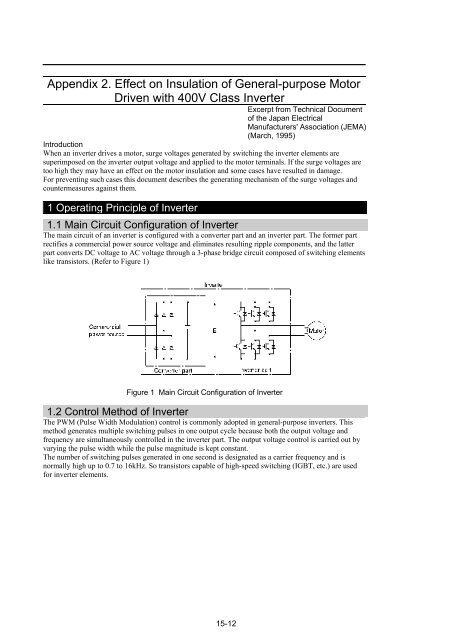
The main circuit of an inverter is configured with a converter part and an inverter part. The former part<br />
rectifies a commercial power source voltage and eliminates resulting ripple components, and the latter<br />
part converts DC voltage to AC voltage through a 3-phase bridge circuit composed of switching elements<br />
like transistors. (Refer to Figure 1)<br />
Figure 1 Main Circuit Configuration of Inverter<br />
1.2 Control Method of Inverter<br />
The PWM (Pulse Width Modulation) control is commonly adopted in general-purpose inverters. This<br />
method generates multiple switching pulses in one output cycle because both the output voltage and<br />
frequency are simultaneously controlled in the inverter part. The output voltage control is carried out by<br />
varying the pulse width while the pulse magnitude is kept constant.<br />
The number of switching pulses generated in one second is designated as a carrier frequency and is<br />
normally high up to 0.7 to 16kHz. So transistors capable of high-speed switching (IGBT, etc.) are used<br />
for inverter elements.<br />
15-12