
You also want an ePaper? Increase the reach of your titles
YUMPU automatically turns print PDFs into web optimized ePapers that Google loves.
2 Noise<br />
A summary of the noise generated in inverters and its effect on devices susceptible to noise is described<br />
below.<br />
2.1 Inverter Noise<br />
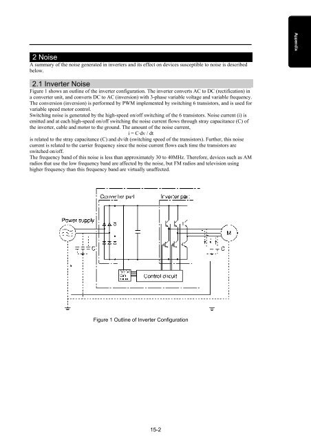
Figure 1 shows an outline of the inverter configuration. The inverter converts AC to DC (rectification) in<br />
a converter unit, and converts DC to AC (inversion) with 3-phase variable voltage and variable frequency.<br />
The conversion (inversion) is performed by PWM implemented by switching 6 transistors, and is used for<br />
variable speed motor control.<br />
Switching noise is generated by the high-speed on/off switching of the 6 transistors. Noise current (i) is<br />
emitted and at each high-speed on/off switching the noise current flows through stray capacitance (C) of<br />
the inverter, cable and motor to the ground. The amount of the noise current,<br />
i = C·dv / dt<br />
is related to the stray capacitance (C) and dv/dt (switching speed of the transistors). Further, this noise<br />
current is related to the carrier frequency since the noise current flows each time the transistors are<br />
switched on/off.<br />
The frequency band of this noise is less than approximately 30 to 40MHz. Therefore, devices such as AM<br />
radios that use the low frequency band are affected by the noise, but FM radios and television using<br />
higher frequency than this frequency band are virtually unaffected.<br />
Figure 1 Outline of Inverter Configuration<br />
15-2