You also want an ePaper? Increase the reach of your titles
YUMPU automatically turns print PDFs into web optimized ePapers that Google loves.
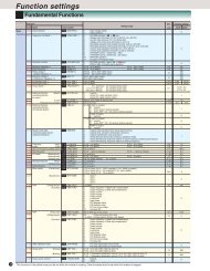
14. Replacement Data<br />
14.6.2 Replacing VG3<br />
FRENIC5000 VG3 FRENIC5000 VG7S<br />
Function<br />
codes<br />
Name<br />
Function<br />
codes<br />
Name<br />
01 Motor rotating speed detection value display − LED monitor<br />
02 Motor rotating speed setting value display − LED monitor<br />
03 Load speed detection value display − LED monitor<br />
04 Torque current reference value display − LED monitor<br />
05 Torque reference value display − LED monitor<br />
06 Motor output display − LED monitor<br />
07 Inverter output current display − LED monitor<br />
08 Motor temperature display − LED monitor<br />
09 Input signal (1) display − LCD monitor<br />
0A Input signal (2) display − LCD monitor<br />
0B Output signal display − LCD monitor<br />
0C Operation mode display − LCD monitor<br />
0D Soft switch (1) display − LCD monitor<br />
0E Soft switch (2) display LCD monitor<br />
0F Magnetic-flux quantity − LED monitor<br />
10 Protection of setting data (11-3F) −<br />
11 Acceleration time 1 F07 Acceleration time 1<br />
12 Deceleration time 1 F08 Deceleration time 1<br />
F67 S-curve acceleration start side 1<br />
13 S-curve applied range<br />
F68<br />
F69<br />
S-curve acceleration end side 1<br />
S-curve deceleration start side 1<br />
F70 S-curve deceleration end side 1<br />
14 Multistep speed setting value 1 C05 Multistep speed 1<br />
15 Multistep speed setting value 2 C06 Multistep speed 2<br />
16 Multistep speed setting value 3 C07 Multistep speed 3<br />
17 Multistep speed setting value 4 C08 Multistep speed 4<br />
18 Multistep speed setting value 5 C09 Multistep speed 5<br />
19 Acceleration time 2 C46 Acceleration time 2<br />
1A Deceleration time 2 C47 Deceleration time 2<br />
1B Speed reference input gain F17 Gain(Speed setting signal 12)<br />
20 ASR P(1) F61 ASR1 P<br />
21 ASR I (1) F62 ASR1 I<br />
22 Speed setting constant on filtering (1) F64 ASR1 input filter<br />
23 Speed detection constant on filtering (1) F65 ASR1 detection filter<br />
24 ASR P(2) C40 ASR2 P<br />
25 ASR I (2) C41 ASR2 I<br />
26 Speed setting constant on filtering (2) C43 ASR2 input filter<br />
27 Speed detection constant on filtering (2) C44 ASR2 detection filter<br />
28 Droop quantity H28 Droop control<br />
29 ASR time constant of P changeover switch C70 ASR switching time<br />
2A<br />
Torque limiter value 1/Torque bias command<br />
value 1<br />
F44 Torque limiter value (Level 1)<br />
2B<br />
Torque limiter value 2/Torque bias command<br />
value 2<br />
F45 Torque limiter value (Level 2)<br />
2C<br />
Torque limiter value 3/Torque bias command<br />
value 3<br />
−<br />
2D Torque limiter value 4 −<br />
2E Magnetic-flux command level H44 Magnetic-flux command value<br />
2F Magnetic-flux command level at light load F73 Magnetic-flux level at light load<br />
30 Zero speed detection level F37 Stop speed<br />
31<br />
Arbitrary speed detection level<br />
(Absolute value)<br />
E39 Speed detection level 1<br />
32 Arbitrary speed detection level (With polarity) E40 Speed detection level 2<br />
33 Speed equivalence detection level E42 Speed equivalence<br />
34 Speed agreement detection level E43 Speed agreement<br />
35 Torque detection level E46 Torque detection level 1<br />
36 Overload early warning detection level E33 Inverter overload early warning<br />
37 Motor overheat early warning detection level E31 Motor overheat early warning<br />
Adjustment is possible through E69 to<br />
38 Output calibration coefficient of load meter − 71, by allocating the torque meter into<br />
AO1 to 3.<br />
Adjustment is possible through E69 to<br />
39 Output calibration coefficient of speedometer − 71, by allocating the speedometer into<br />
AO1 to 3.<br />
14-23