
You also want an ePaper? Increase the reach of your titles
YUMPU automatically turns print PDFs into web optimized ePapers that Google loves.
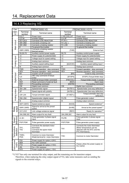
14. Replacement Data<br />
14.4.3 Replacing VG<br />
Cat-<br />
egory<br />
Main circuit<br />
Analog input<br />
Digital input<br />
Analog output<br />
Relay<br />
output<br />
Speed<br />
detection<br />
Temperature<br />
detection<br />
Option power<br />
supply<br />
FRENIC5000 VG FRENIC5000 VG7S<br />
Terminal<br />
symbol<br />
Terminal name<br />
Terminal<br />
symbol<br />
Terminal name<br />
R,S,T Power input L1/R,L2/S,L3/T Power input<br />
U,V,W Inverter output U,V,W Inverter output<br />
DC1,DC2 Connects a DC REACTOR P1,P(+) Connects a DC REACTOR<br />
DB1,DB2 Connects a braking unit P(+),N(−) Connects a braking unit<br />
DB1,DB2 Connects a braking resistor P(+),DB Connects a braking resistor<br />
E To ground the inverter G To ground the inverter<br />
DBR1,DBR2<br />
Connects a braking resistor<br />
thermal sensor.<br />
[THR] External fault<br />
R0,S0,T0 Auxiliary control power supply R0,T0 Auxiliary control power supply<br />
13 Power supply for potentiometer 13 Power supply for potentiometer<br />
12 Voltage input for speed setting 12 Voltage input for speed setting<br />
11 Analog input common 11 Analog input common<br />
V1 Auxiliary speed setting input [AUX-N1] Auxiliary speed setting input 1<br />
M Analog input common M Analog input common<br />
FWD Forward operation ⋅ stop command FWD Forward operation ⋅ stop command<br />
REV Reverse operation ⋅ stop command REV Reverse operation ⋅ stop command<br />
BX Inverter cut-off command [BX] Coast-to stop command<br />
ILS<br />
DEC stop command of torque<br />
limiter<br />
[STOP3] STOP3 (Torque limiter stop)<br />
ITL External torque limiter command [F40-CCL] Torque limiter (mode 1) cancel<br />
RST Reset command of external fault [RST] Alarm reset<br />
EXT Pre-exciting command [EXITE] Pre-exciting command<br />
CM Digital input common CM Digital input common<br />
SM+,SM− Speedometer signal [N-FB1+] Speedometer (one-way deflection)<br />
SP Speed signal with polarity [N-FB1±] Speedometer (two-way deflection)<br />
LM+,LM− Torque ammeter signal [IT-REF±]<br />
Torque ammeter (two-way<br />
deflection)<br />
DM+,DM− Speedometer (digital) signal FA,FB Pulse generator output<br />
M Analog output common M Analog output common<br />
SST1,SST2 Speed existence signal [N-EX] Speed existence* 1)<br />
SAR1,SAR2<br />
Signal for arrival at the preset<br />
speed.<br />
14-17<br />
[N-AR] Arrival at the preset speed* 1)<br />
UV1,UV2 Link voltage existence signal [RDY] Ready for operation* 1)<br />
30A,30B,30C Alarm output for any fault 30A,30B,30C Alarm output for any fault<br />
A+,B+<br />
Pulse generator 2-phase signal<br />
input<br />
PA,PB<br />
Pulse generator 2-phase signal<br />
input<br />
PGP,PGM Pulse generator power supply PGP,PGM Pulse generator power supply<br />
TH1,<br />
TH2<br />
THRC,<br />
PGS<br />
Connects the standard motor<br />
thermistor<br />
Connects the spare motor<br />
thermistor<br />
Common to motor thermistor<br />
Shield terminal for motor thermistor<br />
P24 Power supply for option (+24V) −<br />
M24 For +24V common −<br />
P15 Power supply for option (+15V) −<br />
(M) For ±15V common −<br />
N15 Power supply for option (−15V) −<br />
TH1<br />
Connects the motor thermistor<br />
(Motor temperature can be<br />
detected with the NTC and the<br />
PTC thermistors).<br />
THC Common to motor thermistor<br />
Please utilize the power supply on<br />
the market.<br />
*1) VG7 has only one terminal for relay output, and the remaining are for transistor output.<br />
Therefore, when replacing the relay output signal of VG, take some measures such as sending the<br />
signals to the external relays.