Appendix
Appendix Appendix
13. Function Code List Type [34]: Communication error codes 15 8 7 0 Description of alarms in the communication through the link (RS-485, T-Link, field bus). The following data is set to the monitor data M26 according to the communication status. The codes listed in the column "KEYPAD panel display" is displayed on the KEYPAD panel as a communication error . Code KEYPAD panel display Communication error name Description 0 - No communication error 1 Normal communication 2 A data is written to an unused address of the function code (writing to address out of the specified range is defined separately). 3 Data is read from missing function code address in the middle of continuous read. The data will be "0000". 4 Writing to the S area while link operation is disabled. The data will not be reflected and cause no error. 5 A data out of range is written to the S area. The data is written after adjusted to the upper or the lower limit. 6 Access from another link or the KEYPAD panel occurs during data writing (EEPROM other than the S area is accessed). 7 Writing to operation data (such as tuning or initialization) during multiple function codes are being written once through the link. The inverter decides that the procedure is canceled and continues the writing. 8 Writing to/reading from option function codes that are not displayed on the KEYPAD panel. 9 Writing/reading a special function code for the lifting machine in the standard mode 10 Writing/reading a function code for the standard mode in the lifting machine mode 1 to 32 - Alarm codes specific to the VG7S Alarm codes specific to models other than communication errors. 33 to 70 - Not used 71 04 Checksum error, CRC error Software error Checksum value or CRC value does not match. 72 05 Parity error Hardware error Parity does not match. 73 06 Others (such as overrun, framing) Physical (reception) errors other than above. 74 01 Format error Incorrect format. 75 01 Command error Characters requesting transmission are incorrect. Characters terminating transmission are not in the specified order. Codes other than the specified commands are transmitted. 76 07 Link priority error 1 Writing to the S area through RS485 while a link option is installed. 2 Writing to the S area through a link with lower priority while multiple link options are installed. 77 07 No right to write function code data Not used for VG7S 78 02 Function code error 1 Access to a data out of the address range of the function codes (such as access to a data over F80). 2 Writing data over 16 words. 79 07 Error on writing to writedisabled data 1 Write-disabled function codes (Read-only data or the M area). 2 Function codes write-disabled during operation. 3 Writing through the link to data out of the S area in "write-disabled through link" mode. Note that F00 or "Write enable for KEYPAD" cannot protect from writing through the link. 4 Function codes that cannot be written through the link (link function codes: H31 to 40). 5 Writing to M1 function code (P) area when motor parameters are protected. 6 Writing through the link in the copy mode operation of the KEYPAD panel. 80 03 Data error Written data is out of the setting range in the area other than the S area. 81 07 Error during writing Another writing request comes from the same source while writing function code data (EEPROM other than the S area is accessed). Note: The alarm codes 1 to 32 constitute a code system specific to the VG7S different from the assignment for the general-purpose inverters. The communication error codes 71 to 81 are common to the different models. Note that some causes of alarm are specific to models. The KEYPAD panel does not display raw communication error codes but the values in the "KEYPAD panel display" column in the table above. The KEYPAD panel displays "∗∗" when it receives data that does not have a corresponding "KEYPAD panel display" in the table above. 13-33
Type [35]: X function normally open/closed Type [36]: Y function normally open/closed 15 8 7 0 Type [40] to [99] These types are reserved for the manufacturer. Users can considers these types as type [0] to use. Type [82]: M1 Motor Selection Code KW display HP display Code KW display HP display Code KW display HP display 0 00:0.75-2 00:1-2 13 13:45-2S 13:60-2S 26 26:45-4Y 26:60-4Y 1 01:1.5-2 01:2-2 14 14:55-2 14:75-2 27 27:45-4S 27:60-4S 2 02:2.2-2 02:3-2 15 15:75-2 15:100-2 28 28:55-4 28:75-4 3 03:3.7-2 03:5-2 16 16:90-2 16:125-2 29 29:75-4 29:100-4 4 04:5.5-2 04:7.5-2 17 17:3.7-4 17:5-4 30 30:90-4 30:125-4 5 05:7.5-2 05:10-2 18 18:5.5-4 18:7.5-4 31 31:110-4 31:150-4 6 06:11-2 06:15-2 19 19:7.5-4 19:10-4 32 32:132-4 32:175-4 7 07:15-2 07:20-2 20 20:11-4 20:15-4 33 33:160-4 33:200-4 8 08:18.5-2 08:25-2 21 21:15-4 21:20-4 34 34:200-4 34:250-4 9 09:22-2 09:30-2 22 22:18.5-4 22:25-4 35 35:220-4 35:300-4 10 10:30-2 10:40-2 23 23:22-4 23:30-4 36 36:P-OTR 36:P-OTR 11 11:37-2 11:50-2 24 24:30-4 24:40-4 37 37:OTHER 37:OTHER 12 12:45-2Y 12:60-2Y 25 25:37-4 25:50-4 Type [125]: Control output 1 15 8 7 0 [35] X function [36] Y function 0) X1 Y1 1) X2 Y2 2) X3 Y3 3) X4 Y4 4) X5 Y5 5) X6 6) X7 7) X8 8) X9 13-34 0: Normally open 1: Normally closed 0) Inverter running [RUN] 1) Speed existence [N-EX] 2) Speed agreement [N-AG] 3) Speed equivalence [N-AR] 4) Detected speed 1 [N-DT1] 5) Detected speed 2 [N-DT2] 6) Detected speed 3 [N-DT3] 7) Stopping on undervoltage [LU] 8) Detected torque polarity (braking/driving) [B/D] 9) Torque limiting [TL] 10) Detected torque 1 [T-DT1] 11) Detected torque 2 [T-DT2] 12) KEYPAD operation mode [KP] 13) Inverter stoppage [STOP] 14) Operation ready output [RDY] 15) Magnetic-flux detection signal [MF-DT]
- Page 2 and 3: 12. Operation Data 12.1 Frequency R
- Page 4 and 5: 12. Operation Data 12.5 Impact load
- Page 6 and 7: 12. Operation Data 12.8 Speed-torqu
- Page 8: 12. Operation Data 12.11 Comparison
- Page 11 and 12: 13.2 Function Code List 13.2.1 Func
- Page 13 and 14: Communication Control type: Availab
- Page 15 and 16: Communication Control type: Availab
- Page 17 and 18: Communication Control type: Availab
- Page 19 and 20: Communication Control type: Availab
- Page 21 and 22: Communication address Fcode Functio
- Page 23 and 24: Fcode Communication address 485 num
- Page 25 and 26: H: High Performance Functions Commu
- Page 27 and 28: Communication address Fcode 485 Lin
- Page 29 and 30: Communication address Fcode 485 Lin
- Page 31 and 32: Communication address Fcode 485 Lin
- Page 33 and 34: Communication address Fcode Functio
- Page 35 and 36: 13.3 Function Code List Dedicated t
- Page 37 and 38: 485 Min increment Unit Type number
- Page 39 and 40: Type [14]: Cause of alarm 15 12 8 7
- Page 41: Type [29]: Inverter model (common t
- Page 46 and 47: 14. Replacement Data When replacing
- Page 48 and 49: 14. Replacement Data 14.2.2 Replaci
- Page 50 and 51: 14. Replacement Data 14.3 Terminal
- Page 52 and 53: 14. Replacement Data 14.3.2 Replaci
- Page 54 and 55: 14. Replacement Data 14.3.3 Replaci
- Page 56 and 57: 14. Replacement Data 14.4 Terminal
- Page 58 and 59: 14. Replacement Data Cat- ego- ry T
- Page 60 and 61: 14. Replacement Data Cat- ego- ry A
- Page 62 and 63: 14. Replacement Data 14.4.3 Replaci
- Page 64 and 65: 14. Replacement Data � Difference
- Page 66 and 67: 14. Replacement Data FRENIC5000 VG5
- Page 68 and 69: 14. Replacement Data 14.6.2 Replaci
- Page 70 and 71: 14. Replacement Data FRENIC5000 VG3
- Page 72 and 73: 14. Replacement Data � 400V serie
- Page 74 and 75: 14. Replacement Data � 400V serie
- Page 76 and 77: 14. Replacement Data � 400V serie
- Page 78 and 79: 14. Replacement Data 14.8.2 Replaci
- Page 80 and 81: 14. Replacement Data 14.9 Options 1
- Page 82: 14. Replacement Data 14.9.3 Replaci
- Page 85 and 86: 2 Noise A summary of the noise gene
- Page 87 and 88: C C Figure 5 Electrostatic Noise (3
- Page 89 and 90: Table 1 Noise Prevention Methods Wi
- Page 91 and 92: 3.3 Specific Examples Table 2 lists
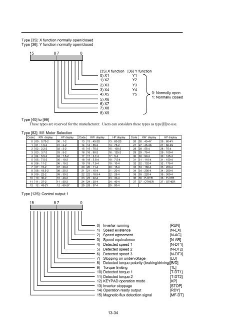
Type [35]: X function normally open/closed<br />
Type [36]: Y function normally open/closed<br />
15 8 7 0<br />
Type [40] to [99]<br />
These types are reserved for the manufacturer. Users can considers these types as type [0] to use.<br />
Type [82]: M1 Motor Selection<br />
Code KW display HP display Code KW display HP display Code KW display HP display<br />
0 00:0.75-2 00:1-2 13 13:45-2S 13:60-2S 26 26:45-4Y 26:60-4Y<br />
1 01:1.5-2 01:2-2 14 14:55-2 14:75-2 27 27:45-4S 27:60-4S<br />
2 02:2.2-2 02:3-2 15 15:75-2 15:100-2 28 28:55-4 28:75-4<br />
3 03:3.7-2 03:5-2 16 16:90-2 16:125-2 29 29:75-4 29:100-4<br />
4 04:5.5-2 04:7.5-2 17 17:3.7-4 17:5-4 30 30:90-4 30:125-4<br />
5 05:7.5-2 05:10-2 18 18:5.5-4 18:7.5-4 31 31:110-4 31:150-4<br />
6 06:11-2 06:15-2 19 19:7.5-4 19:10-4 32 32:132-4 32:175-4<br />
7 07:15-2 07:20-2 20 20:11-4 20:15-4 33 33:160-4 33:200-4<br />
8 08:18.5-2 08:25-2 21 21:15-4 21:20-4 34 34:200-4 34:250-4<br />
9 09:22-2 09:30-2 22 22:18.5-4 22:25-4 35 35:220-4 35:300-4<br />
10 10:30-2 10:40-2 23 23:22-4 23:30-4 36 36:P-OTR 36:P-OTR<br />
11 11:37-2 11:50-2 24 24:30-4 24:40-4 37 37:OTHER 37:OTHER<br />
12 12:45-2Y 12:60-2Y 25 25:37-4 25:50-4<br />
Type [125]: Control output 1<br />
15 8 7 0<br />
[35] X function [36] Y function<br />
0) X1 Y1<br />
1) X2 Y2<br />
2) X3 Y3<br />
3) X4 Y4<br />
4) X5 Y5<br />
5) X6<br />
6) X7<br />
7) X8<br />
8) X9<br />
13-34<br />
0: Normally open<br />
1: Normally closed<br />
0) Inverter running [RUN]<br />
1) Speed existence [N-EX]<br />
2) Speed agreement [N-AG]<br />
3) Speed equivalence [N-AR]<br />
4) Detected speed 1 [N-DT1]<br />
5) Detected speed 2 [N-DT2]<br />
6) Detected speed 3 [N-DT3]<br />
7) Stopping on undervoltage [LU]<br />
8) Detected torque polarity (braking/driving) [B/D]<br />
9) Torque limiting [TL]<br />
10) Detected torque 1 [T-DT1]<br />
11) Detected torque 2 [T-DT2]<br />
12) KEYPAD operation mode [KP]<br />
13) Inverter stoppage [STOP]<br />
14) Operation ready output [RDY]<br />
15) Magnetic-flux detection signal [MF-DT]


