Chebyshev IIR filter sharpening implemented on FPGA - Telfor 2008
Chebyshev IIR filter sharpening implemented on FPGA - Telfor 2008
Chebyshev IIR filter sharpening implemented on FPGA - Telfor 2008

You also want an ePaper? Increase the reach of your titles
YUMPU automatically turns print PDFs into web optimized ePapers that Google loves.
<str<strong>on</strong>g>Chebyshev</str<strong>on</strong>g> <str<strong>on</strong>g>IIR</str<strong>on</strong>g> <str<strong>on</strong>g>filter</str<strong>on</strong>g> <str<strong>on</strong>g>sharpening</str<strong>on</strong>g><br />
<str<strong>on</strong>g>implemented</str<strong>on</strong>g> <strong>on</strong> <strong>FPGA</strong><br />
Vladimir M. Poučki, Andrej Žemva, Miroslav D. Lutovac, Senior Member, IEEE, and Tomaž Karčnik<br />
Abstract — Filter design technique called <str<strong>on</strong>g>filter</str<strong>on</strong>g> <str<strong>on</strong>g>sharpening</str<strong>on</strong>g><br />
(a new <str<strong>on</strong>g>filter</str<strong>on</strong>g> created from an existing <str<strong>on</strong>g>filter</str<strong>on</strong>g> in which the<br />
passband ripple is reduced and the stopband attenuati<strong>on</strong> is<br />
increased) is presented. The proposed method is applied <strong>on</strong><br />
the <str<strong>on</strong>g>Chebyshev</str<strong>on</strong>g> infinite impulse resp<strong>on</strong>se (<str<strong>on</strong>g>IIR</str<strong>on</strong>g>) <str<strong>on</strong>g>filter</str<strong>on</strong>g> whereas<br />
in the past the 30 year old technique had been applied <strong>on</strong>ly to<br />
FIR <str<strong>on</strong>g>filter</str<strong>on</strong>g>s with c<strong>on</strong>stant group delay. Using a small area of<br />
field programmable gate array chips for placing <strong>on</strong>ly two<br />
fourth-order <str<strong>on</strong>g>IIR</str<strong>on</strong>g> <str<strong>on</strong>g>filter</str<strong>on</strong>g>s, and the hardware folding<br />
techniques, a number of different <str<strong>on</strong>g>filter</str<strong>on</strong>g> specificati<strong>on</strong>s can be<br />
fulfilled. The method is attractive for <str<strong>on</strong>g>filter</str<strong>on</strong>g> designs without<br />
extensive analysis of n<strong>on</strong>linear effects and for the fixed point<br />
implementati<strong>on</strong>s.<br />
Keywords — <str<strong>on</strong>g>Chebyshev</str<strong>on</strong>g> <str<strong>on</strong>g>filter</str<strong>on</strong>g>, <str<strong>on</strong>g>filter</str<strong>on</strong>g> <str<strong>on</strong>g>sharpening</str<strong>on</strong>g>, Field<br />
Programmable Gate Array – <strong>FPGA</strong>, <str<strong>on</strong>g>filter</str<strong>on</strong>g> design, Infinite<br />
Impulse Resp<strong>on</strong>se <str<strong>on</strong>g>IIR</str<strong>on</strong>g> <str<strong>on</strong>g>filter</str<strong>on</strong>g><br />
I. INTRODUCTION<br />
HE operating rate of field programmable gate array<br />
T (<strong>FPGA</strong>) chips can be c<strong>on</strong>siderably larger than the<br />
processing rate for digital signal processing (DSP)<br />
applicati<strong>on</strong>s in audio, communicati<strong>on</strong> or c<strong>on</strong>trol systems.<br />
The used area of <strong>FPGA</strong> chips can be significantly reduced<br />
by time sharing the hardware resources [1], that is, the<br />
same <str<strong>on</strong>g>implemented</str<strong>on</strong>g> <str<strong>on</strong>g>filter</str<strong>on</strong>g> structure is used several times<br />
between two successive input samples. An excellent<br />
soluti<strong>on</strong> is the hardware folding technique to timemultiplex<br />
many algorithm operati<strong>on</strong>s <strong>on</strong>to a single<br />
functi<strong>on</strong>al unit such as an adder or a multiplier [1].<br />
Although this technique can be used for the<br />
implementati<strong>on</strong> of infinite impulse resp<strong>on</strong>se (<str<strong>on</strong>g>IIR</str<strong>on</strong>g>) <str<strong>on</strong>g>filter</str<strong>on</strong>g>s as<br />
cascade c<strong>on</strong>necti<strong>on</strong> of the sec<strong>on</strong>d-order secti<strong>on</strong> (SOS)<br />
<str<strong>on</strong>g>filter</str<strong>on</strong>g>s, the design by an inexperienced user may fail to<br />
fulfill the <str<strong>on</strong>g>filter</str<strong>on</strong>g> specificati<strong>on</strong> due to n<strong>on</strong>linear effects such<br />
as overflow and dead-band effects, pure dynamic range of<br />
SOS <str<strong>on</strong>g>filter</str<strong>on</strong>g>s, or coefficient quantizati<strong>on</strong>.<br />
This work was supported by the Slovenian Ministry for Higher<br />
Educati<strong>on</strong>, Science and Technology and the Serbian Ministry of Science<br />
(Grant TR-11002).<br />
V. M. Poučki and T. Karčnik, R&D Department, Instrumentati<strong>on</strong><br />
Technologies, Velika pot 22, 5250 Solkan, Slovenia (Ph<strong>on</strong>e: +386-5-<br />
3352621; Fax: +386-5-3352601; e-mail: vladimir@i-tech.si).<br />
A. Žemva, Laboratory for Integrated Circuit Design, Faculty of<br />
Electrical Engineering, University of Ljubljana, Tržaška cesta 25, 1000<br />
Ljubljana, Slovenia; (e-mail: andrej.zemva@fe.uni-lj.si).<br />
M. D. Lutovac, School of Electrical Engineering, University of<br />
Belgrade, Bulevar Kralja Aleksandra 73, 11000 Belgrade, Serbia;<br />
(e-mail: lutovac@etf.rs).<br />
Filter <str<strong>on</strong>g>sharpening</str<strong>on</strong>g> is a known technique in <str<strong>on</strong>g>filter</str<strong>on</strong>g> theory -<br />
a new <str<strong>on</strong>g>filter</str<strong>on</strong>g> is created from the existing low-order <str<strong>on</strong>g>filter</str<strong>on</strong>g><br />
and is sharpened in such a way that the passband ripple is<br />
reduced and the stopband attenuati<strong>on</strong> is increased [2]. This<br />
technique is not applicable to <str<strong>on</strong>g>filter</str<strong>on</strong>g>s having n<strong>on</strong>-c<strong>on</strong>stant<br />
group delay such as minimum phase finite impulse<br />
resp<strong>on</strong>se (FIR) <str<strong>on</strong>g>filter</str<strong>on</strong>g>s or <str<strong>on</strong>g>IIR</str<strong>on</strong>g> <str<strong>on</strong>g>filter</str<strong>on</strong>g>s.<br />
Digital <str<strong>on</strong>g>filter</str<strong>on</strong>g> design becomes an effortless task because<br />
it can be accomplished using powerful software tools.<br />
Unfortunately, many designs of selective <str<strong>on</strong>g>IIR</str<strong>on</strong>g> <str<strong>on</strong>g>filter</str<strong>on</strong>g>s can<br />
fail to fulfill specificati<strong>on</strong>s in fixed point implementati<strong>on</strong>s<br />
with <strong>FPGA</strong> chips. The <str<strong>on</strong>g>filter</str<strong>on</strong>g> design can be simplified if the<br />
same kind of universal <str<strong>on</strong>g>filter</str<strong>on</strong>g> secti<strong>on</strong>s can be used as<br />
building blocks, rather than design for each set of<br />
specificati<strong>on</strong>s and perform thorough analysis of n<strong>on</strong>linear<br />
effects.<br />
In this paper we present a design method that c<strong>on</strong>sists<br />
of a cascade c<strong>on</strong>necti<strong>on</strong> of several low-order <str<strong>on</strong>g>IIR</str<strong>on</strong>g> <str<strong>on</strong>g>filter</str<strong>on</strong>g><br />
secti<strong>on</strong>s. The attenuati<strong>on</strong> in the passband can be kept very<br />
low, while increasing the number of repeated secti<strong>on</strong>s<br />
increases the stopband attenuati<strong>on</strong>. The advantage of an<br />
<strong>FPGA</strong> implementati<strong>on</strong> of the proposed <str<strong>on</strong>g>filter</str<strong>on</strong>g> <str<strong>on</strong>g>sharpening</str<strong>on</strong>g><br />
method is illustrated by an example.<br />
II. EQUIRIPPLE RATIONAL FUNCTION<br />
A. Rati<strong>on</strong>al magnitude functi<strong>on</strong><br />
It is easy to establish [3] the equiripple character of<br />
rati<strong>on</strong>al magnitude functi<strong>on</strong>s<br />
2 2<br />
2 1 + ε T ( x)<br />
R(<br />
x)<br />
= N r<br />
(1)<br />
2 2<br />
( 1 + ε T ( x)<br />
) µ<br />
D r<br />
with the c<strong>on</strong>straint<br />
2 2 µ<br />
ε N = ( 1 + ε D ) − 1<br />
(2)<br />
In these equati<strong>on</strong>s T r (x)<br />
is the r-th order <str<strong>on</strong>g>Chebyshev</str<strong>on</strong>g><br />
polynomial. The c<strong>on</strong>stants ε N and ε D are called the<br />
ripple factors while the integer µ can be of any value<br />
µ ≥ 2 .<br />
B. Minima and maxima of the magnitude functi<strong>on</strong><br />
The examinati<strong>on</strong> of the first and the sec<strong>on</strong>d derivatives<br />
of equati<strong>on</strong> (1) show that the independent variables of the<br />
minima x min of the rati<strong>on</strong>al functi<strong>on</strong> R (x)<br />
are<br />
determined by the roots of the equati<strong>on</strong>s<br />
'<br />
Tr ( x)<br />
= 0, Tr<br />
( x)<br />
(3)<br />
At x min and x = 1 the value of the magnitude functi<strong>on</strong><br />
432
is 1:<br />
R ( x min ) = 1, R(1)<br />
= 1<br />
(4)<br />
The positi<strong>on</strong> of maximum can be found from<br />
2<br />
T r ( x max ) − k = 0<br />
(5)<br />
2 2<br />
ε − µε<br />
k = N D , µ = 2,3,4,... (6)<br />
2 2<br />
ε N ε D ( µ − 1)<br />
The ripple factor (the maximal variati<strong>on</strong> of the<br />
magnitude functi<strong>on</strong>)<br />
2<br />
2<br />
ε = R(<br />
xmax<br />
) − 1<br />
(7)<br />
becomes<br />
2<br />
2<br />
µ −1<br />
2 ε ⎛ ( 1) ⎞<br />
⎜ µ − ε<br />
ε = N N ⎟ − 1 (8)<br />
µ 2 ⎜ 2 2<br />
µ ε<br />
⎟<br />
D ⎝ ε N − ε D ⎠<br />
The c<strong>on</strong>stant k can be expressed as a functi<strong>on</strong> of ε N or<br />
ε D<br />
i = µ<br />
⎛ µ ⎞ 2i<br />
∑ ⎜ ⎟ε<br />
D<br />
i i<br />
k = 2 ⎝ ⎠<br />
(9)<br />
=<br />
i = µ<br />
2i<br />
⎛ µ ⎞ 2i<br />
( µ − 1) ε D ∑ ⎜ ⎟ε<br />
D<br />
i = 1 ⎝ i ⎠<br />
All roots of equati<strong>on</strong> (5) are real for 0 < ε D < 1 and<br />
µ > 2 , which provide the equiripple character of the<br />
magnitude functi<strong>on</strong>.<br />
The positi<strong>on</strong>s of the minima x min are not functi<strong>on</strong> of<br />
ε N or ε D . The positi<strong>on</strong>s of the maxima x max change<br />
slightly with µ and ε N or ε D . Therefore, the shape of<br />
the magnitude is practically the same for any µ and ε N<br />
or ε D for 0 ≤ x ≤ 1 . C<strong>on</strong>versely, the magnitude functi<strong>on</strong><br />
decreases 6 µ r dB/octave.<br />
The equiriple rati<strong>on</strong>al functi<strong>on</strong> can be used as<br />
approximating functi<strong>on</strong> for <str<strong>on</strong>g>filter</str<strong>on</strong>g> <str<strong>on</strong>g>sharpening</str<strong>on</strong>g> because it is<br />
based <strong>on</strong> processing the date µ times with the same startup<br />
<str<strong>on</strong>g>filter</str<strong>on</strong>g> (<str<strong>on</strong>g>Chebyshev</str<strong>on</strong>g> <str<strong>on</strong>g>filter</str<strong>on</strong>g>).<br />
III. DESIGN METHOD<br />
The simplest soluti<strong>on</strong> of <str<strong>on</strong>g>filter</str<strong>on</strong>g> <str<strong>on</strong>g>sharpening</str<strong>on</strong>g> is <str<strong>on</strong>g>filter</str<strong>on</strong>g>ing the<br />
data k times with the existing <str<strong>on</strong>g>filter</str<strong>on</strong>g>. If the original <str<strong>on</strong>g>filter</str<strong>on</strong>g>’s<br />
transfer functi<strong>on</strong> is H(z), then the new transfer functi<strong>on</strong> is<br />
(H(z)) k . The new <str<strong>on</strong>g>filter</str<strong>on</strong>g> has the same band edges and the<br />
minimum attenuati<strong>on</strong>, in decibels, is k times larger in the<br />
stopband. The drawback is that the passband ripple is also<br />
k times larger in decibels. This soluti<strong>on</strong> improves the<br />
stopband but degrades the passband.<br />
The <str<strong>on</strong>g>filter</str<strong>on</strong>g> <str<strong>on</strong>g>sharpening</str<strong>on</strong>g> of analog <str<strong>on</strong>g>filter</str<strong>on</strong>g>s [3] provides very<br />
low passband ripple and the Q factors of the dominant<br />
transfer-functi<strong>on</strong> pole pairs are reduced. An active RC<br />
<str<strong>on</strong>g>filter</str<strong>on</strong>g> cannot be efficiently <str<strong>on</strong>g>implemented</str<strong>on</strong>g> as a selective <str<strong>on</strong>g>filter</str<strong>on</strong>g><br />
with very high pole-Q factors, while multiple low-Q factor<br />
SOS <str<strong>on</strong>g>filter</str<strong>on</strong>g>s can be massively produced. Using the bilinear<br />
transformati<strong>on</strong>, analog <str<strong>on</strong>g>filter</str<strong>on</strong>g>s with low-Q factors are<br />
transformed into digital <str<strong>on</strong>g>filter</str<strong>on</strong>g>s that are more robust for<br />
fixed point implementati<strong>on</strong> [4]. Therefore, the same<br />
method as used in [3] can be used for digital <str<strong>on</strong>g>filter</str<strong>on</strong>g><br />
<str<strong>on</strong>g>sharpening</str<strong>on</strong>g>.<br />
The standard <str<strong>on</strong>g>filter</str<strong>on</strong>g> H s (z) should be chosen to be simple<br />
for implementati<strong>on</strong>. For example, the standard <str<strong>on</strong>g>filter</str<strong>on</strong>g> can be<br />
the fourth-order <str<strong>on</strong>g>Chebyshev</str<strong>on</strong>g> <str<strong>on</strong>g>filter</str<strong>on</strong>g> that has small passband<br />
ripple (say A s =0.1 dB) and it c<strong>on</strong>sists of two SOS <str<strong>on</strong>g>filter</str<strong>on</strong>g>s<br />
−1<br />
−2<br />
−1<br />
−2<br />
1 + 2z<br />
+ z 1 + 2z<br />
+ z<br />
H ( z)<br />
=<br />
(10)<br />
s<br />
−1<br />
− 2 −1<br />
− 2<br />
1 + as1z<br />
+ as2<br />
z 1 + as3z<br />
+ as4<br />
z<br />
The coefficients are shown in Table 1.<br />
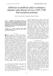
The <str<strong>on</strong>g>filter</str<strong>on</strong>g> has a stopband attenuati<strong>on</strong> of 8 dB at the<br />
stopband edge f s =0.135; the passband edge frequency is<br />
f p =0.1. The target <str<strong>on</strong>g>filter</str<strong>on</strong>g>, the cascaded c<strong>on</strong>necti<strong>on</strong> of µ basic<br />
<str<strong>on</strong>g>filter</str<strong>on</strong>g>s, should have the minimum stopband attenuati<strong>on</strong> 40<br />
dB; it also has large passband ripple 0.1•µ dB. To achieve<br />
a stopband attenuati<strong>on</strong> of 40 dB, the number of cascades µ<br />
is equal to 5. Let us design the fourth-order <str<strong>on</strong>g>Chebyshev</str<strong>on</strong>g><br />
<str<strong>on</strong>g>filter</str<strong>on</strong>g> H i (z) that has the passband ripple 0.5 dB for µ=5.<br />
The coefficients are shown in Table 1.<br />
TABLE 1: COEFFICIENTS OF THE FILTER.<br />
Coefficients<br />
a s1<br />
–1.26232<br />
a s2<br />
0.44004<br />
a s3<br />
–1.310268<br />
a s4<br />
0.73834<br />
a c1<br />
–1.46622<br />
a c2<br />
0.58087<br />
a c3<br />
–1.44789<br />
a 0.814144<br />
c4<br />
The transfer functi<strong>on</strong> of the new <str<strong>on</strong>g>filter</str<strong>on</strong>g><br />
H(z)=(H s (z)) µ /H i (z) can be simplified H(z)=(H s (z)) µ-1 H c (z)<br />
in such a way that a new forth order <str<strong>on</strong>g>filter</str<strong>on</strong>g> becomes H c (z)=<br />
H s (z)/H i (z)<br />
−1<br />
−2<br />
−1<br />
−2<br />
1 + a 1z<br />
+ a 2z<br />
1 + a<br />
( )<br />
3z<br />
+ a 4z<br />
H z = c c<br />
c c (11)<br />
c<br />
−1<br />
−2<br />
−1<br />
−2<br />
1 + as1z<br />
+ as2z<br />
1 + as3z<br />
+ as4<br />
z<br />
The transfer functi<strong>on</strong> of cascaded c<strong>on</strong>necti<strong>on</strong> of m<br />
standard and n compensati<strong>on</strong> secti<strong>on</strong>s becomes<br />
m<br />
H ( z)<br />
= ( H s ( z)<br />
) ( H c ( z)<br />
) n (12)<br />
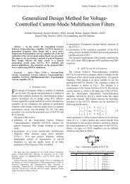
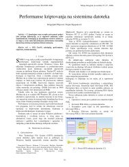
In Figures 1, 2 and 3, the attenuati<strong>on</strong>s of <str<strong>on</strong>g>filter</str<strong>on</strong>g>s are<br />
shown for a number of combinati<strong>on</strong>s of m and n. The<br />
minimum stopband attenuati<strong>on</strong> increases with the number<br />
of H s (z) secti<strong>on</strong>s while the passband ripple is the same as<br />
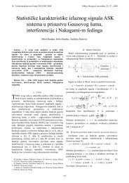
for the standard secti<strong>on</strong>, in this case 0.1 dB. The passband<br />
ripple is smaller than the ripple of the standard <str<strong>on</strong>g>filter</str<strong>on</strong>g><br />
⎛<br />
µ −1<br />
µ µ ⎞<br />
⎜ 1 ( µ − 1) ( α − 1)<br />
A = 10 n log<br />
⎟ (13)<br />
n 10<br />
µ −1<br />
µ µ −1<br />
µ −1<br />
⎝ ( α − 1) α µ ( α − 1) ⎠<br />
for<br />
A /10<br />
α = 10 s , m = n(<br />
µ − 1) (14)<br />
For example, for µ=5, n=1, A s =0.1 dB, the input data is<br />
<str<strong>on</strong>g>filter</str<strong>on</strong>g>ed 4 times using the standard <str<strong>on</strong>g>filter</str<strong>on</strong>g> H s (z) and <strong>on</strong>es<br />
using the compensati<strong>on</strong> <str<strong>on</strong>g>filter</str<strong>on</strong>g> H c (z); the overall passband<br />
ripple is A n =0.0058 dB and the minimum stopband<br />
attenuati<strong>on</strong> is A s min =26 dB. For n=2, the data is <str<strong>on</strong>g>filter</str<strong>on</strong>g>ed 8<br />
times using H s (z) and twice using H c (z), the overall<br />
passband ripple is A n =0.0116 dB and A s min =52 dB.<br />
Attenuati<strong>on</strong> of <str<strong>on</strong>g>filter</str<strong>on</strong>g>s depends <strong>on</strong> the number of<br />
433
standard and compensati<strong>on</strong> <str<strong>on</strong>g>filter</str<strong>on</strong>g>s used. Solid lines<br />
represent transfer functi<strong>on</strong>s with passband ripple between<br />
0dB and 0.1dB, dotted lines depict transfer functi<strong>on</strong>s with<br />
passband ripple between -0.1dB and 0dB, while dashed<br />
lines are transfer functi<strong>on</strong>s with passband ripple smaller<br />
than 0.1dB.<br />
Attenuati<strong>on</strong> (dB)<br />
100<br />
80<br />
m= 1, n=0<br />
60<br />
m= 4, n=1<br />
m= 5, n=1<br />
m= 7, n=2<br />
40<br />
m= 8, n=2<br />
m= 9, n=2<br />
m=11, n=3<br />
20<br />
m=12, n=3<br />
m=13, n=3<br />
m=15, n=4<br />
0<br />
m=16, n=4<br />
0 0.1 0.2 0.3 0.4 0.5<br />
Frequency<br />
Fig. 1. Attenuati<strong>on</strong> of <str<strong>on</strong>g>filter</str<strong>on</strong>g>s for different number of<br />
standard and compensati<strong>on</strong> <str<strong>on</strong>g>filter</str<strong>on</strong>g>s.<br />
Attenuati<strong>on</strong> (dB)<br />
1<br />
0.1<br />
0<br />
-0.1<br />
m= 1, n=0<br />
m= 4, n=1<br />
m= 5, n=1<br />
m= 7, n=2<br />
m= 8, n=2<br />
m= 9, n=2<br />
m=11, n=3<br />
m=12, n=3<br />
m=13, n=3<br />
m=15, n=4<br />
m=16, n=4<br />
0.02 0.04 0.07 0.1<br />
Frequency<br />
Fig. 2. Attenuati<strong>on</strong> of <str<strong>on</strong>g>filter</str<strong>on</strong>g>s in the passband.<br />
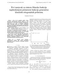
Figure 4 dem<strong>on</strong>strates the implementati<strong>on</strong> using field<br />
programmable gate array chips with <strong>on</strong>ly two time-folded<br />
fourth-order <str<strong>on</strong>g>filter</str<strong>on</strong>g>s. Each <str<strong>on</strong>g>filter</str<strong>on</strong>g> c<strong>on</strong>sists of two cascaded<br />
SOS <str<strong>on</strong>g>filter</str<strong>on</strong>g>s. Therefore, the two sec<strong>on</strong>d-order secti<strong>on</strong>s are<br />
standard secti<strong>on</strong>s. The first SOS secti<strong>on</strong> has the transfer<br />
functi<strong>on</strong> zeros <strong>on</strong> the unit circle, while the sec<strong>on</strong>d secti<strong>on</strong><br />
has zeros within the unit circle. In fact, the c<strong>on</strong>trol circuit<br />
is very simple, it c<strong>on</strong>sists of multiplexer and<br />
demultiplexer. It looks like some up-sampler or downsampler<br />
in the classic multirate system, but it effectively<br />
works similarly to the classic time multiplexing system.<br />
C<strong>on</strong>sequently, the timing diagram is very simple.<br />
The term small area is used to emphasis that the used<br />
area is always the same and that it does not depend <strong>on</strong> the<br />
actual transfer functi<strong>on</strong> order. For example, with m=16<br />
and n=4, the used are will be approximately 20 times<br />
larger. On the other hand, using the multiplier-less<br />
technique, the general multipliers can be <str<strong>on</strong>g>implemented</str<strong>on</strong>g><br />
using <strong>on</strong>ly binary shifters, or a few adders and binary<br />
shifters, which can additi<strong>on</strong>ally reduce the used area <strong>on</strong><br />
the <strong>FPGA</strong> chips.<br />
The appropriate chip is selected according to the<br />
required functi<strong>on</strong>ality of the device, in which the<br />
<str<strong>on</strong>g>implemented</str<strong>on</strong>g> <str<strong>on</strong>g>filter</str<strong>on</strong>g> is used for <str<strong>on</strong>g>filter</str<strong>on</strong>g>ing <strong>on</strong>ly.<br />
In some applicati<strong>on</strong>s it may be useful to use different<br />
<str<strong>on</strong>g>filter</str<strong>on</strong>g> specificati<strong>on</strong>s, with larger and smaller stopband<br />
attenuati<strong>on</strong>, but with the same edge frequencies and very<br />
small passband ripple. Instead of implementing two <str<strong>on</strong>g>filter</str<strong>on</strong>g>s,<br />
this <str<strong>on</strong>g>filter</str<strong>on</strong>g> can be used. Thus, the used area of <strong>on</strong>e <str<strong>on</strong>g>filter</str<strong>on</strong>g> is<br />
smaller than the used area of two <str<strong>on</strong>g>filter</str<strong>on</strong>g>s.<br />
The benefits of using this method are (1) the usage of<br />
the same chip area regardless of the transfer functi<strong>on</strong><br />
order, and (2) the possible savings in the number of<br />
general multipliers that are <str<strong>on</strong>g>implemented</str<strong>on</strong>g> using a small<br />
number of adders and binary shifters. More details <strong>on</strong> the<br />
multiplier-less technique can be found in [4].<br />
m= 1, n=0<br />
m= 4, n=1<br />
m= 5, n=1<br />
m= 7, n=2<br />
m= 8, n=2<br />
m= 9, n=2<br />
m=11, n=3<br />
m=12, n=3<br />
m=13, n=3<br />
m=15, n=4<br />
m=16, n=4<br />
86<br />
78<br />
70<br />
60<br />
52<br />
44<br />
34<br />
26<br />
8<br />
0<br />
0.1 0.11 0.12 0.135 0.15<br />
Frequency<br />
Fig. 3. Attenuati<strong>on</strong> of <str<strong>on</strong>g>filter</str<strong>on</strong>g>s in the transiti<strong>on</strong>.<br />
IV. CONCLUSION<br />
Using a small area of <strong>FPGA</strong> chips for placing <strong>on</strong>ly two<br />
fourth-order <str<strong>on</strong>g>IIR</str<strong>on</strong>g> <str<strong>on</strong>g>filter</str<strong>on</strong>g>s, and hardware folding techniques<br />
to time-multiplex operati<strong>on</strong>s <strong>on</strong>to two <str<strong>on</strong>g>filter</str<strong>on</strong>g>s, a number of<br />
different <str<strong>on</strong>g>filter</str<strong>on</strong>g>s can be <str<strong>on</strong>g>implemented</str<strong>on</strong>g>. All <str<strong>on</strong>g>filter</str<strong>on</strong>g>s have the<br />
same passband and stopband edges, the same or smaller<br />
passband ripples, and arbitrary minimum stopband<br />
attenuati<strong>on</strong>s that are functi<strong>on</strong>s of the down-sampling and<br />
up-sampling factor. The method called sharpened <str<strong>on</strong>g>IIR</str<strong>on</strong>g><br />
<str<strong>on</strong>g>filter</str<strong>on</strong>g>s is especially attractive for practicing engineers<br />
without extensive knowledge of <str<strong>on</strong>g>filter</str<strong>on</strong>g> theory, and for <str<strong>on</strong>g>filter</str<strong>on</strong>g><br />
design without thorough and extensive analysis using <str<strong>on</strong>g>filter</str<strong>on</strong>g><br />
design tools.<br />
LITERATURA<br />
[1] L. Narinder and B. Taylor, “Designing C<strong>on</strong>trol Circuits for High<br />
Performance DSP Systems,” Xilinx DSP Magazine, pp. 55 57, 2005.<br />
[2] M. D<strong>on</strong>adio, “Lost Knowledge Refound: Sharpened FIR Filters,”<br />
IEEE Signal Processing Magazine, pp. 61-63, 2003.<br />
[3] D. Rabrenović and M. Lutovac, “Low Q equiripple functi<strong>on</strong>s of<br />
n<strong>on</strong>minimum order,” Electr<strong>on</strong>ics Letters, pp. 447-448, 1990.<br />
[4] M. Lutovac, D. Tošić and B. Evans, Filter Design for Signal<br />
Processing Using MATLAB and Mathematica. Upper Saddle River,<br />
NJ: Prentice Hall, 2001.<br />
96<br />
Attenuati<strong>on</strong> (dB)<br />
434
Select m<br />
sel<br />
Select<br />
In<br />
Gateway In<br />
System<br />
Generator<br />
reinterpret<br />
Resource<br />
Estimator<br />
Select n<br />
↑9<br />
Upsample m<br />
↑2<br />
Upsample n<br />
d0<br />
d1<br />
Mux 1<br />
sel<br />
d0<br />
d1<br />
Mux 2<br />
Hs(z)<br />
z -1<br />
z -1<br />
Hc(z)<br />
z -1<br />
z -1<br />
↓9<br />
Downsample m<br />
↓2<br />
Downsample n<br />
sel<br />
d0<br />
d1<br />
Mux 3<br />
reinterpret<br />
Out<br />
Gateway Out<br />
Fig. 4. Implementati<strong>on</strong> of a sharpened <str<strong>on</strong>g>IIR</str<strong>on</strong>g> <str<strong>on</strong>g>filter</str<strong>on</strong>g> that c<strong>on</strong>sists of two <str<strong>on</strong>g>filter</str<strong>on</strong>g>s Hs(z) and Hc(z), c<strong>on</strong>trol circuits, two-input<br />
multiplexers and up-sample and down-sample blocks that c<strong>on</strong>trol the data rate through the <str<strong>on</strong>g>filter</str<strong>on</strong>g>s.<br />
435