Roadway Materials and Material Sources
Roadway Materials and Material Sources
Roadway Materials and Material Sources

Create successful ePaper yourself
Turn your PDF publications into a flip-book with our unique Google optimized e-Paper software.
Chapter 12<br />
Roadw<br />
oadway <strong><strong>Material</strong>s</strong><br />
<strong>and</strong> <strong>Material</strong> <strong>Sources</strong><br />
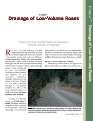
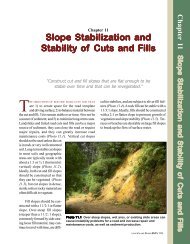
LOW-VOLUME ROAD surfaces <strong>and</strong> structural<br />
sections are typically built from native<br />
materials that must support light vehicles <strong>and</strong><br />
may have to support heavy commercial truck traffic.<br />
In addition, low-volume roads should have a surface<br />
that, when wet, will not rut <strong>and</strong> will provide adequate<br />
traction for vehicles. The surface of native soil roads<br />
is also an exposed area that can produce significant<br />
amounts of sediment, especially if rutted (Photo<br />
12.1).<br />
<strong>Roadway</strong> <strong><strong>Material</strong>s</strong><br />
It is usually desirable <strong>and</strong>,<br />
in many cases, necessary to<br />
add subgrade structural support<br />
or to improve the roadbed<br />
native soil surface with<br />
materials such as gravel,<br />
coarse rocky soil, crushed<br />
aggregate, cobblestone, concrete<br />
block, or some type of<br />
bituminous seal coat or asphalt<br />
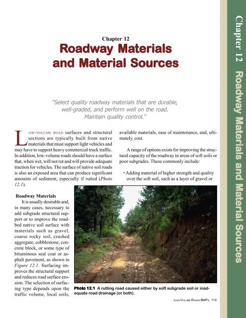
pavement, as shown in<br />
Figure 12.1. Surfacing improves<br />
the structural support<br />
<strong>and</strong> reduces road surface erosion.<br />
The selection of surfacing<br />
type depends upon the<br />
traffic volume, local soils,<br />
“Select quality roadway materials that are durable,<br />
well-graded, <strong>and</strong> perform well on the road.<br />
Maintain quality control.”<br />
available materials, ease of maintenance, <strong>and</strong>, ultimately,<br />
cost.<br />
A range of options exists for improving the structural<br />
capacity of the roadway in areas of soft soils or<br />
poor subgrades. These commonly include:<br />
• Adding material of higher strength <strong>and</strong> quality<br />
over the soft soil, such as a layer of gravel or<br />
Photo 12.1 A rutting road caused either by soft subgrade soil or inadequate<br />
road drainage (or both).<br />
LOW-VOLUME ROADS BMPS : 115<br />
Chapter 12 Roadw<br />
oadway <strong><strong>Material</strong>s</strong> <strong>and</strong> <strong>Material</strong> <strong>Sources</strong><br />
Sour
Figur<br />
igure 12.1 Commonly used low-volume road surfacing types <strong>and</strong> structural sections.<br />
a. Native Soil<br />
— Native (In-Place) Soil<br />
b. Aggregate<br />
— Crushed Surface Aggregate or Gravel<br />
— Native Soil<br />
c. Aggregate <strong>and</strong> Base<br />
— Crushed Surface Aggregate or Gravel<br />
— Aggregate Base<br />
— Native Soil<br />
d. Cobblestone<br />
— Cobblestones<br />
— S<strong>and</strong><br />
— Native Soil<br />
e. Concrete Block<br />
— Concrete Blocks<br />
— S<strong>and</strong><br />
— Native Soil<br />
— Asphalt Pavement<br />
f. Asphalt Surfacing<br />
— Aggregate Base<br />
— Aggregate Sub-Base (Optional)<br />
— Native Soil<br />
g. Typical Aggregate<br />
Surfaced Road<br />
Template<br />
Fill Slope Road Surface Ditch<br />
LOW-VOLUME ROADS BMPS:116
crushed aggregate;<br />
• Improving the soft soil in<br />
place (in-situ) by mixing it<br />
with stabilization additives<br />
such as lime, cement, asphalt,<br />
or chemicals;<br />
• Bridging over the soft soil<br />
with materials such as<br />
geotextiles or wood pieces<br />
(corduroy);<br />
• Removing the soft or poor<br />
soil <strong>and</strong> replacing it with a<br />
high quality soil or rocky<br />
material;<br />
• Limiting the use of the road<br />
during periods of wet<br />
weather when clay soils are<br />
soft;<br />
• Compacting the native soil<br />
to increase its density <strong>and</strong><br />
strength; <strong>and</strong><br />
• Keeping moisture out of the<br />
soil with effective roadway<br />
drainage or encapsulating<br />
the soil to keep water out.<br />
Various soil stabilization materials<br />
such as oils, lime, cements,<br />
resins, lignin, chlorides, enzymes,<br />
<strong>and</strong> chemicals may be used to improve<br />
the material properties of<br />
the in-place soil. They may be very<br />
cost-effective in areas where aggregate<br />
or other materials are difficult<br />
to locate or are expensive.<br />
The best soil stabilization material<br />
to use depends on cost, soil<br />
type, performance <strong>and</strong> local experience.<br />
Test sections are often<br />
needed to determine the most desirable<br />
<strong>and</strong> cost-effective product.<br />
However, many soil stabilizers still<br />
Photo 12.2 Stabilize the roadway surface with crushed rock (or<br />
other surfacing) on steep grades, in areas of soft soil, or in erosive<br />
soils.<br />
need some type of wearing surface.<br />
A stabilized road surface improves<br />
traction <strong>and</strong> offers erosion<br />
protection as well as structural<br />
support.<br />
Gravel, pit run rock, select<br />
material, or crushed aggregate are<br />
the most common improved surfacing<br />
materials used on low-volume<br />
roads (Photo 12.2). Aggregate<br />
is sometimes used only as<br />
“fill” material in ruts. However, it<br />
is more desirable to place it as a<br />
full structural section, as shown<br />
in Figure 12.2. The roadway surfacing<br />
aggregate must perform<br />
two basic functions. It must have<br />
high enough quality <strong>and</strong> be thick<br />
enough to provide structural support<br />
to the traffic <strong>and</strong> prevent rutting,<br />
<strong>and</strong> it must be well graded<br />
<strong>and</strong> mixed with sufficient fines,<br />
preferably with some plasticity, to<br />
prevent raveling <strong>and</strong><br />
washboarding.<br />
Necessary aggregate thickness<br />
typically ranges from 10 to<br />
30 cm, depending on soil strength,<br />
traffic, <strong>and</strong> climate. Specific aggregate<br />
thickness design procedures<br />
are found in the Selected<br />
References. Over very weak soils<br />
(CBR less than 3), aggregate<br />
thickness can be reduced with the<br />
use of geotextile or geogrid<br />
subgrade reinforcement. Also,<br />
geotextile layers are useful over<br />
soft soils to separate the aggregate<br />
from the soil, keep it uncontaminated,<br />
<strong>and</strong> extend the useful<br />
life of the aggregate.<br />
Figure 12.3 presents some of<br />
the physical properties <strong>and</strong><br />
tradeoffs of various soil-aggregate<br />
mixtures, first with no fines (no<br />
material passing the #200 sieve,<br />
or .074 mm size), second with an<br />
ideal percentage of fines (6-15%),<br />
<strong>and</strong> finally with excessive fines<br />
(over 15 to 30%). Figure 12.4<br />
shows the typical gradation ranges<br />
of aggregates used in road construction,<br />
how the materials, ranging<br />
from coarse to fine, best perform<br />
for a road, <strong>and</strong> the approxi-<br />
LOW-VOLUME ROADS BMPS : 117
Figur<br />
igure 12.2 Aggregate options to prevent rutting.<br />
POOR<br />
a. Minimal aggregate<br />
filled into ruts when<br />
they develop.<br />
MEDIOCRE– ADEQUATE<br />
b. Ruts filled plus<br />
addition of 10-15 cmthick<br />
layer of aggregate.<br />
BEST<br />
c. Full structural section<br />
placed upon a reshaped<br />
compacted subgrade.<br />
If crushed rock or gravel is<br />
not available, use coarse soil,<br />
wood chips or soil stabilizers.<br />
For surfacing aggregate use<br />
crushed rock, gravel or 3 cm<br />
minus rock with fines.<br />
10-30 cm<br />
Aggregate Surface or<br />
Asphalt Surfacing<br />
Aggregate Base Course or Clean<br />
Fractured Rock<br />
(5-10 cm size or smaller)<br />
0-30 cm min.<br />
LOW-VOLUME ROADS BMPS:118
Figur<br />
igure 12.3<br />
Physical states of soil-aggregate mixtures. (Adapted from Yoder <strong>and</strong><br />
Witczak, 1975)<br />
Aggregate with<br />
no Fines<br />
• Grain-to-grain contact<br />
• Variable density<br />
• High Permeability<br />
• Non-Frost Susceptible<br />
• High stability when<br />
confined, low if unconfined<br />
• Not affected by water<br />
• Difficult to compact<br />
• Ravels easily<br />
Aggregate with<br />
Sufficient Fines for<br />
Maximum Density<br />
• Grain-to-grain contact<br />
with increased resistance<br />
against deformation<br />
• Increased to maximum<br />
density<br />
• Low permeability<br />
• Frost susceptible<br />
• Relatively high stability<br />
in confined or unconfined<br />
conditions<br />
• Not greatly affected by<br />
adverse water conditions<br />
• Moderately easy to<br />
compact<br />
• Good road performance<br />
Aggregate with High<br />
Amount of Fines<br />
(>30 percent)<br />
• Grain-to-grain contact<br />
destroyed, aggregate is<br />
"floating" in soil<br />
• Decreased density<br />
• Low permeability<br />
• Frost susceptible<br />
• Low stability <strong>and</strong> low<br />
strength<br />
• Greatly affected by water<br />
• Easy to compact<br />
• Dusts easily<br />
LOW-VOLUME ROADS BMPS : 119
Figur<br />
igure 12.4 Gradation ranges of roadway surfacing materials <strong>and</strong> their performance characteristics.<br />
(Adapted from R. Charles, 1997 <strong>and</strong> the Association of Asphalt Paving Technologists)<br />
PERCENT FINER BY WEIGHT (PERCENT PASSING - %)<br />
PERCENT COARSER BY WEIGHT<br />
NOTE: Gradation Ranges Shown Are Approximate.<br />
The best roadbed surfacing materials have some plasticity <strong>and</strong> are well graded. They have<br />
gradations parallel to the curves shown above, <strong>and</strong> are closest to the “Ideal” dashed curve in the<br />
middle of the gradation ranges shown.<br />
• Construction operations or<br />
heavy traffic during wet or<br />
rainy periods on roads with<br />
clay rich or fine-grained soil<br />
surfaces that form ruts.<br />
• Allowing ruts <strong>and</strong> potholes to<br />
form over 5 to 10 cm deep in<br />
LOW-VOLUME ROADS BMPS:120<br />
PRACTICES TO AVOID<br />
the roadway surface.<br />
• Road surface stabilization<br />
using coarse rock larger than<br />
about 7.5 cm. Coarse rock is<br />
difficult to drive upon or keep<br />
stabilized on the road surface,<br />
<strong>and</strong> it damages tires.<br />
• Using surfacing materials<br />
that are fine grain soils,<br />
soft rock that will degrade<br />
to fine sediment, or clean,<br />
poorly graded coarse rock<br />
that will erode, ravel, or<br />
washboard.
mate limitations to the desirable<br />
gradation ranges. Note that the<br />
desirable percentage of fines in an<br />
aggregate can be sensitive to the<br />
climate or road environment. In<br />
semi arid to desert regions, a relatively<br />
high percentage of fines,<br />
such as 15 to 20%, with moder-<br />
• Stabilize the roadway<br />
surface on roads that form<br />
ruts or ravel excessively.<br />
Common surface stabilization<br />
techniques include<br />
using 10-15 cm of crushed<br />
aggregate; local pit run or<br />
grid roll rocky material<br />
(Photo 12.4); cobblestone<br />
surfacing; wood chips or<br />
fine logging slash; or soils<br />
mixed <strong>and</strong> stabilized with<br />
cement, asphalt, lime,<br />
lignin, chlorides, chemicals,<br />
or enzymes.<br />
• For heavy traffic on soft<br />
subgrade soils, use a<br />
single, thick structural<br />
section consisting of at<br />
least 20-30 cm of surfacing<br />
aggregate. Alternatively,<br />
use a structural<br />
section consisting of a 10-<br />
30 cm thick layer of base<br />
aggregate or coarse<br />
fractured rock, capped<br />
with a 10-15 cm thick<br />
layer of surfacing aggregate<br />
(Figure 12.2-BEST).<br />
Note that soft clay-rich<br />
tropical soils <strong>and</strong> heavy<br />
tire loads may require a<br />
thicker structural section.<br />
The structural depth<br />
needed is a function of the<br />
traffic volume, loads <strong>and</strong><br />
soil type, <strong>and</strong> should<br />
ate plasticity, is desirable. In a high<br />
rainfall “wet” environment, such<br />
as tropical, coastal mountain, or<br />
jungle areas, a low percentage,<br />
such as 5 to 10% fines, is desirable<br />
to prevent rutting <strong>and</strong> maintain<br />
a stable road surface.<br />
RECOMMENDED PRACTICES<br />
ideally be determined<br />
through local experience<br />
or testing, such as using<br />
the CBR (California<br />
Bearing Ratio) test.<br />
• Maintain a 3-5% road<br />
cross-slope with insloping,<br />
outsloping, or a crown to<br />
rapidly move water off the<br />
road surface (see Figure<br />
7.1).<br />
• Grade or maintain the<br />
roadway surface before<br />
significant potholes,<br />
washboarding, or ruts<br />
form (see Figure 4.5).<br />
• Compact the embankment<br />
material, road surface<br />
material or aggregate<br />
during construction <strong>and</strong><br />
maintenance to achieve a<br />
dense, smooth road surface<br />
<strong>and</strong> thus reduce the<br />
amount of water that can<br />
soak into the road (Photo<br />
12.5).<br />
• “Spot” stabilize local wet<br />
areas <strong>and</strong> soft areas with<br />
10-15 cm of coarse rocky<br />
material. Add more rock<br />
as needed (Figure 12.2).<br />
• Stabilize the road surface<br />
in sensitive areas near<br />
streams <strong>and</strong> at drainage<br />
Ideally, aggregate surfacing<br />
material is (1) hard, durable, <strong>and</strong><br />
crushed or screened to a minus 5<br />
cm size; (2) well graded to<br />
achieve maximum density; (3)<br />
contains 5-15% clayey binder to<br />
prevent raveling; <strong>and</strong> (4) has a<br />
Plasticity Index of 2 to 10. The<br />
crossings to minimize road<br />
surface erosion.<br />
• Control excessive road<br />
dust with water, oils,<br />
wood chips, or use of<br />
other dust palliatives.<br />
• Blend coarse aggregate<br />
<strong>and</strong> fine clay-rich soil<br />
(when available) to produce<br />
a desirable composite<br />
roadway material that is<br />
coarse yet well-graded<br />
with 5-15 % fines for<br />
binder (see Figures 12.3<br />
<strong>and</strong> 12.4).<br />
• Use project construction<br />
quality control, through<br />
visual observation <strong>and</strong><br />
materials sampling <strong>and</strong><br />
testing, to achieve specified<br />
densities <strong>and</strong> quality,<br />
well-graded road materials<br />
(Photo 12.6).<br />
• On higher st<strong>and</strong>ard, high<br />
traffic volume roads<br />
(collectors, principals, or<br />
arterials) use appropriate,<br />
cost effective surfacing<br />
materials such as oils,<br />
cobblestone, paving blocks<br />
(Photo 12.7), bituminous<br />
surface treatments (chip<br />
seals) (Photo 12.8), <strong>and</strong><br />
asphalt concrete pavements.<br />
LOW-VOLUME ROADS BMPS : 121
Photo 12.3 A road in need of<br />
maintenance <strong>and</strong> surfacing.<br />
Add roadway surface stabilization<br />
or do maintenance with<br />
grading <strong>and</strong> shaping of the<br />
surface to remove ruts <strong>and</strong><br />
potholes before significant road<br />
damage occurs, to achieve<br />
good road surface drainage,<br />
<strong>and</strong> to define the roadbed.<br />
Photo 12.4 A grid roller can be<br />
used to produce a desirable<br />
surfacing material when the<br />
coarse rock is relatively soft.<br />
Level <strong>and</strong> compact the roadway<br />
surface aggregate to achieve a<br />
dense, smooth, well-drained<br />
riding surface.<br />
Photo 12.5 Compaction of soil<br />
<strong>and</strong> aggregate is typically the<br />
least expensive way to improve<br />
the strength <strong>and</strong> performance<br />
of the material. Compaction is<br />
useful <strong>and</strong> cost-effective both<br />
for the stability of fill embankments<br />
<strong>and</strong> for the road surface.<br />
LOW-VOLUME ROADS BMPS:122
Photo 12.6 Here, a “nuclear<br />
gauge” is being used to check<br />
the density of aggregate. Use<br />
project construction quality<br />
control, gradation <strong>and</strong> density<br />
testing, etc., as needed to<br />
achieve the desirable materials<br />
properties for the project.<br />
Photo 12.7 Concrete blocks<br />
(Adoquin) or cobblestone offer<br />
an intermediate alternative to<br />
aggregate <strong>and</strong> pavement road<br />
surfacing. These materials are<br />
labor intensive to construct <strong>and</strong><br />
maintain, but are very costeffective<br />
in many areas.<br />
Photo 12.8 A chip seal road<br />
surface being compacted. A<br />
variety of surfacing materials<br />
can be used, depending on<br />
availability, cost, <strong>and</strong> performance.<br />
LOW-VOLUME ROADS BMPS : 123
surfacing applied to the road must<br />
be maintainable in order to prevent<br />
rutting <strong>and</strong> erosion. Significant<br />
deterioration of the road can<br />
occur if ruts, raveling,<br />
washboarding, or surface erosion<br />
are not controlled (Photo 12.3).<br />
Road damage can be greatly reduced<br />
by restricting road use during<br />
wet conditions if road management<br />
allows for this option.<br />
Compaction is usually the<br />
most cost-effective method to improve<br />
the quality, including<br />
strength <strong>and</strong> water resistance, of<br />
subgrade soils <strong>and</strong> to improve the<br />
performance of aggregate surfacing.<br />
It increases the density <strong>and</strong><br />
reduces the void spaces in the<br />
material, making it less susceptible<br />
to moisture. Thus, compaction is<br />
useful to protect the investment<br />
in road aggregate, maximize its<br />
strength, minimize loss of fines,<br />
<strong>and</strong> prevent raveling. Road performance<br />
has been excellent in<br />
some semi-arid regions with the<br />
use of blended local materials,<br />
very high compaction st<strong>and</strong>ards,<br />
<strong>and</strong> a waterproof membrane such<br />
as a bituminous seal coat.<br />
Compaction can best be<br />
achieved with a minimum of effort<br />
if the soil or aggregate is well<br />
graded <strong>and</strong> if it is moist. Ideally,<br />
it should be close to the “optimum<br />
moisture content” as determined<br />
by tests such as the “Proctor”<br />
Moisture-Density Tests. Expansive<br />
soils should be compacted on<br />
the wet side of optimum. H<strong>and</strong><br />
tamping can be effective, but only<br />
when done in thin lifts (2-8 cm)<br />
<strong>and</strong> ideally at a moisture content<br />
a few percent above optimum.<br />
The best compaction equipment<br />
for granular soils <strong>and</strong> aggregate<br />
is a vibratory roller. A tamping,<br />
or sheepsfoot roller is most<br />
effective on clay soils. A smooth<br />
drum, steel wheel roller is ideal for<br />
compaction of the roadway surface.<br />
Vibratory plates or rammers,<br />
such as “wackers”, are ideal in<br />
confined spaces. No one piece of<br />
equipment is ideal for all soils, but<br />
the best all-purpose equipment for<br />
earthwork in most mixed soils is<br />
a pneumatic tire roller that produces<br />
good compaction in a wide<br />
range of soil types, from aggregates<br />
to cohesive silty soils.<br />
<strong><strong>Material</strong>s</strong> <strong>Sources</strong><br />
The use of local materials<br />
sources, such as borrow pits <strong>and</strong><br />
quarries, can produce major cost<br />
savings for a project compared to<br />
the cost of hauling materials from<br />
distant, often commercial,<br />
sources. However, the quarry or<br />
borrow pit material quality must<br />
be adequate. <strong>Sources</strong> may be<br />
nearby rock outcrops or granular<br />
deposits adjacent to the road or<br />
within the roadway. Road widening<br />
or lowering road grade in fractured,<br />
rocky areas may produce<br />
good construction materials in an<br />
area already impacted by construction.<br />
Rock excavation <strong>and</strong><br />
production may be by h<strong>and</strong> (Photo<br />
12.9), or with the use of various<br />
types of equipment, such as<br />
screens <strong>and</strong> crushers. Relatively<br />
low-cost, on-site materials can result<br />
in the application of considerably<br />
more roadway surfacing<br />
<strong>and</strong> more slope protection with<br />
rock since the materials are readily<br />
available <strong>and</strong> inexpensive. However,<br />
poor quality materials will<br />
require more road maintenance<br />
<strong>and</strong> may have poor performance.<br />
Borrow pits <strong>and</strong> quarries can<br />
have major adverse impacts, including<br />
sediment from a large denuded<br />
area, a change in l<strong>and</strong> use,<br />
impacts on wildlife, safety problems,<br />
<strong>and</strong> visual impacts. Thus<br />
quarry site planning, location, <strong>and</strong><br />
development should usually be<br />
done in conjunction with Environmental<br />
Analysis to determine the<br />
suitability of the site <strong>and</strong> constraints.<br />
A Pit Development Plan<br />
should be required for any quarry<br />
or pit development to define <strong>and</strong><br />
control the use of the site <strong>and</strong> the<br />
materials being extracted. A pit<br />
development plan typically defines<br />
the location of the materials deposit,<br />
the working equipment,<br />
stockpile <strong>and</strong> extraction areas<br />
(Photo 12.10), access roads,<br />
property boundaries, water<br />
sources, <strong>and</strong> final shape of the pit<br />
<strong>and</strong> back slopes. <strong><strong>Material</strong>s</strong> source<br />
extraction can cause long-term<br />
l<strong>and</strong> use changes, so good site<br />
analysis is needed.<br />
In-channel gravel deposits or<br />
stream terrace deposits are often<br />
used as materials sources. Ideally,<br />
deposits in or near streams or rivers<br />
should not be used. Gravel extraction<br />
in active stream channels<br />
can cause significant damage to<br />
the stream, both on-site <strong>and</strong><br />
downstream (or upstream) of the<br />
site. However, it may be reasonable<br />
to remove some materials<br />
from the channel with adequate<br />
study of the fluvial system <strong>and</strong><br />
care in the operation. Some gravel<br />
bar or terrace deposits may be<br />
appropriate for a materials source,<br />
particularly if taken from above<br />
the active river channel. Equip-<br />
LOW-VOLUME ROADS BMPS:124
Photo 12.9 Develop quarries<br />
<strong>and</strong> borrow sites (materials<br />
sources) close to the project<br />
area whenever possible. Either<br />
h<strong>and</strong> labor or equipment may be<br />
appropriate, depending on the<br />
site conditions <strong>and</strong> production<br />
rates.<br />
Photo 12.10 Quarries <strong>and</strong><br />
borrow sites (materials<br />
sources) can provide an excellent,<br />
relatively inexpensive<br />
source of project materials. A<br />
site may require simple excavation,<br />
screening, or crushing to<br />
produce the desired materials.<br />
Control use of the area with a<br />
Pit Development Plan.<br />
ment should not work in the water.<br />
Site reclamation is typically<br />
needed after materials extraction,<br />
<strong>and</strong> reclamation should be an integral<br />
part of site development<br />
<strong>and</strong> included in the materials cost.<br />
Reclamation work should be defined<br />
in a Pit Reclamation Plan.<br />
Reclamation can include conserving<br />
<strong>and</strong> reapplying topsoil, reshaping<br />
the pit, revegetation, drainage,<br />
erosion control, <strong>and</strong> safety measures.<br />
Often, interim site use, closure,<br />
<strong>and</strong> future reuse must also<br />
be addressed. A site may be used<br />
for many years but be closed between<br />
projects, so interim reclamation<br />
may be needed. Roadside<br />
borrow areas are commonly used<br />
as close, inexpensive sources of<br />
material (Photo 12.11). These areas<br />
ideally should be located out<br />
of sight of the road, <strong>and</strong> they too<br />
need reclamation work after use.<br />
The quality of the local material<br />
may be variable or marginal,<br />
<strong>and</strong> the use of local material often<br />
requires extra processing or<br />
quality control. Low quality material<br />
may be produced at a cost<br />
much lower than commercially<br />
available material, but may not<br />
perform well. Zones of good <strong>and</strong><br />
bad material may have to be separated.<br />
The use of local materials,<br />
however, can be very desirable<br />
<strong>and</strong> cost-effective when available<br />
<strong>and</strong> suitable.<br />
LOW-VOLUME ROADS BMPS : 125
RECOMMENDED PRACTICES<br />
• Develop local borrow pits,<br />
quarries <strong>and</strong> pit-run<br />
material sources wherever<br />
practical in a project area.<br />
Ensure that Environmental<br />
Analysis has been done for<br />
the establishment of new<br />
materials sources.<br />
• Use a Pit Development<br />
Plan to define <strong>and</strong> control<br />
the use of local materials.<br />
A Pit Development Plan<br />
should include the location<br />
of the site, extent of<br />
development, excavation,<br />
stockpiling <strong>and</strong> working<br />
areas, shape of the pit,<br />
volume of useable material,<br />
site limitations, a plan<br />
view, cross-sections of the<br />
area, <strong>and</strong> so on. A plan<br />
should also address interim<br />
or temporary closures <strong>and</strong><br />
future operations.<br />
• Develop a Pit Reclamation<br />
Plan in conjunction<br />
with pit planning to return<br />
the area to other long-term<br />
productive uses. A Pit<br />
Reclamation Plan should<br />
include information such<br />
as topsoil conservation<br />
<strong>and</strong> reapplication, final<br />
slopes <strong>and</strong> shaping, drainage<br />
needs, safety measures,<br />
revegetation, <strong>and</strong><br />
erosion control measures<br />
(Photo 12.12).<br />
• Reshape, revegetate <strong>and</strong><br />
control erosion in roadside<br />
borrow areas to minimize<br />
their visual <strong>and</strong> environmental<br />
impacts (Figure<br />
12.5). Locate materials<br />
sources either within the<br />
roadway or out of view of<br />
the road.<br />
• Maintain project quality<br />
control with materials<br />
testing to guarantee the<br />
production of suitable<br />
quality material from<br />
quarry <strong>and</strong> borrow pit<br />
sources.<br />
PRACTICES TO AVOID<br />
• In-stream channel gravel<br />
extraction operations <strong>and</strong><br />
working with equipment in<br />
the stream.<br />
• Developing materials<br />
sources without planning<br />
<strong>and</strong> implementing reclamation<br />
measures.<br />
• Using low quality, questionable,<br />
or unproven<br />
materials without adequate<br />
investigation <strong>and</strong> testing.<br />
LOW-VOLUME ROADS BMPS:126
Figur<br />
igure 12.5 Good <strong>and</strong> bad roadside quarry development practices. (Adapted from Visual Quality<br />
Best Management Practices for Forest Management in Minnesota, 1996)<br />
Good Practices for Quarry Development<br />
DO!<br />
• Screen pit area from road<br />
• Leave gentle slopes<br />
• Reshape <strong>and</strong> smooth the area<br />
• Leave pockets of vegetation<br />
• Seed <strong>and</strong> mulch the area<br />
• Use drainage control measures<br />
• Replace Topsoil<br />
Poor Practices for Quarry Development<br />
DO NOT!<br />
• Expose large, open area<br />
• Leave area barren<br />
• Leave steep or vertical slopes<br />
Ideal Location <strong>and</strong> Sequence of Excavation<br />
3<br />
4<br />
1<br />
2<br />
Road<br />
Locate borrow areas out of sight of the road.<br />
(NOTE: Safe backslope excavation height depends on soil type.<br />
Keep backslopes low, sloped or terraced for safety purposes.)<br />
LOW-VOLUME ROADS BMPS : 127
Photo 12.11 This roadside borrow area lacks drainage <strong>and</strong> erosion<br />
control. Roadside quarry development can be inexpensive <strong>and</strong> useful, but<br />
the areas should be hidden if possible, <strong>and</strong> the areas should be reclaimed<br />
once the project is completed.<br />
Photo 12.12 A reclaimed <strong>and</strong> revegetated borrow site. Reshape, drain,<br />
plant vegetation, <strong>and</strong> rehabilitate borrow pits <strong>and</strong> quarries once the<br />
usable materials are removed <strong>and</strong> use of the area is completed.<br />
LOW-VOLUME ROADS BMPS:128