Smart Non-Default Routing for Clock Power Reduction - UCSD VLSI ...
Smart Non-Default Routing for Clock Power Reduction - UCSD VLSI ...
Smart Non-Default Routing for Clock Power Reduction - UCSD VLSI ...

You also want an ePaper? Increase the reach of your titles
YUMPU automatically turns print PDFs into web optimized ePapers that Google loves.
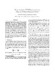
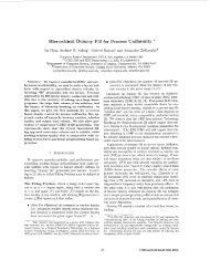
Wire Res. per um<br />
(ohm/um)<br />
Wire Cap. per um (Ff/um)<br />
EM Limit (Irms,mA)<br />
optimization, where wire widths are reduced and spacings can take<br />
on any value that does not result in wire capacitance exceeding<br />
that of the original fixed NDRs, can also significantly reduce track<br />
consumption. Second, analysis and en<strong>for</strong>cement of electrical constraints<br />
readily extend to include coupling noise, noise-induced delay<br />
variation, process variation, and a number of other concerns.<br />
However, the basic optimization will remain the same as what we<br />
study, and we leave such extensions to future work.<br />
4. SNDR WIRE SIZING<br />
4.1 Wire RC Delay Model <strong>for</strong> SNDR<br />
RC modeling of wire is given by Equation (2), where l e , w e and<br />
s e are the length, width and spacing of edge e, respectively.<br />
R e = ρ · le<br />
w e<br />
, C e = ε · lew e<br />
s e<br />
(2)<br />
We assume w e + s e is a constant Y equal to a fixed track pitch.<br />
Then, s e = Y −w e . To obtain linear <strong>for</strong>mulations in w e , we approximate<br />
R per µm and C per µm as functions of x e = ln(w e ) 6 . Then,<br />
R e and C e can be approximated as<br />
R e = (α R · x e + β R ) · l e , C e = (α C · x e + β C ) · l e (3)<br />
where α R , β R , α C and β C are fitting coefficients which we obtain<br />
by linear regression. Figure 5 shows that our suggested model is<br />
fairly accurate with measurements 7 . If the range of wire width<br />
increases, our model may not be applicable. However, these models<br />
are reasonable <strong>for</strong> the general wire width range limited by recent<br />
process technologies.<br />
We use the Elmore delay model [8] to calculate the delay of clock<br />
tree. The delay between node u and v is<br />
D u,v = ∑ (R e · ∑ C i ) (4)<br />
e∈P u→v i∈desc(e)<br />
where P u→v is the path from node u to v.<br />
By substituting clock source s to u in Equations (3) and (4), we<br />
get the clock latency at node v as<br />
L v = ∑ ((α R · x i + β R ) · l i ∑ (α C · x j + β C ) · l j ) (5)<br />
i∈P s→v j∈desc(i)<br />
For wire slew calculation, we apply the PERI model [10]. The<br />
slew at node v, where s is the clock source, is<br />
√<br />
S v = S 2 s + ln9 · D 2 s,v (6)<br />
where S s is the output slew of clock buffer at the clock source.<br />
The output slew of clock buffers depends on the input slew and<br />
the output capacitances. Since the input slew of clock buffer is the<br />
output slew of the upstream net which is constrained by U S , we can<br />
assume U S to be the worst case value. With a constant input slew<br />
U S , we use a piecewise linear model to approximate the output slew<br />
as a function of the total output capacitance.<br />
∑<br />
S s = α S · C e + β S (7)<br />
e∈desc(s)<br />
where α S and β S are fitting coefficients. We assume the total output<br />
capacitance be<strong>for</strong>e optimization as the initial capacitance. This<br />
assumption is pessimistic since the total output capacitance will<br />
be minimized after applying SNDR. However, <strong>for</strong> large sizes of<br />
buffers, which are typically used in clock trees, the output slew is<br />
not very sensitive to the output capacitance. Thus, with reasonable<br />
6 We note that R and C are respectively proportional to, and inversely proportional to,<br />
w e . Taking logs trans<strong>for</strong>ms multiplier and divider into first-order terms.<br />
7 The maximum errors that we have seen are -22% <strong>for</strong> R and -4% <strong>for</strong> C, <strong>for</strong> the SNDR<br />
sets that we study.<br />
pessimism, we obtain a constant S s with given U S and the initial<br />
total capacitance. 8 K u,v = |D s,u − D s,v | (8)<br />
The skew constraint should be checked <strong>for</strong> all pairs of source-tosink<br />
timing paths with the upper bound U K .<br />
2.00<br />
1.50<br />
1.00<br />
0.50<br />
y = -0.9814x + 1.7098<br />
R² = 0.9674<br />
0.00<br />
0.0 0.5 1.0 1.5<br />
SNDR variable x e = ln(w e )<br />
0.15<br />
0.10<br />
0.05<br />
y = 0.0319x + 0.0866<br />
R² = 0.9439<br />
0.00<br />
0.0 0.5 1.0 1.5<br />
SNDR variable x e = ln(w e )<br />
y = 0.6681x + 0.5475<br />
R² = 0.9723<br />
0.00<br />
0.0 0.5 1.0 1.5<br />
SNDR variable x e = ln(w e )<br />
(a) (b) (c)<br />
Figure 5: (a) Wire resistance per unit length (b) wire capacitance per unit length,<br />
and (c) EM limit (I RMS ); each is fitted as a linear function of x e = ln(w e ), where w e<br />
is the wire width in the limited range that we are using.<br />
4.2 EM Current Model and EM Rule<br />
For EM constraints, we use a simplified I RMS model derived from<br />
Black’s Equation [12]. If V dd is the operating voltage, F is the<br />
operating frequency and sw is the switching activity on the net,<br />
∑<br />
I RMS (e) = C i ·V dd · F · √sw (9)<br />
i∈desc(e)<br />
where I RMS (e) is the root mean square current of the edge e. We<br />
use Synopsys 32/28nm PDK [26], where the I RMS limit is defined<br />
as a polynomial function of wire width and the metal layer,<br />
EMLimit(w) = α E w 2 + β E w + γ E (10)<br />
where α E , β E and γ E are fitting coefficients. We obtain a linear<br />
function of x e as shown in Equation (11), where α ′ E and β′ E are fitting<br />
coefficients. For the ranges of SNDRs considered, this model<br />
accurately captures characterized values as shown in Figure 5.<br />
E e,we = α ′ E x e + β ′ E (11)<br />
4.3 Iterative Linear Programming (LP)<br />
To avoid quadratic constraints arising from the Elmore delay<br />
model, we separate the sizing problem into two (alternating) linear<br />
programs by fixing the R values and the C values in alternation.<br />
Our method recalls the rescaled simple iteration of [21], and has<br />
the following steps.<br />
Delay constraints are <strong>for</strong>mulated based on Equation (5). First,<br />
we fix x i with a constant x e,0 (= initial NDR value) and <strong>for</strong>mulate<br />
a linear function of x j (Constr C ). In a similar way, we fix x j<br />
with a constant x 0 and <strong>for</strong>mulate a linear function of x i (Constr R ).<br />
And then, we solve the problem with both the constraints (Constr R<br />
and Constr C ) simultaneously using the objective function (Equation<br />
(1)). Second, we <strong>for</strong>mulate the constraints in the same way<br />
as the first step, but with different initial values x e,1 , which are the<br />
solutions derived from the previous step. We iteratively solve the<br />
problem until all x e <strong>for</strong> each edge e are determined. In our experiments,<br />
our approach obtained results that are essentially identical<br />
to those of the QCP-based method, but with runtime reductions of<br />
6× to 30× 9 .<br />
4.4 Applying SNDR to an Entire <strong>Clock</strong> Tree<br />
In subsections (Section 4.1 ∼ 4.3), we have <strong>for</strong>mulated the SNDR<br />
problem, and proposed an iterative method to optimize a subtree of<br />
clock (a single net). To optimize the entire clock tree, we per<strong>for</strong>m<br />
our SNDR method from the downstream to upstream subnets of<br />
clock tree. Algorithm 1 presents pseudocode of our SNDR flow <strong>for</strong><br />
8 We do not per<strong>for</strong>m buffer sizing since it can lead to larger delay variations and<br />
degrade EM when buffers are upsized.<br />
9 We have compared the runtime with testcase wb_dma_top; the overall runtimes of the<br />
QCP-based method and LP-based method are 170 minutes and 29 minutes respectively<br />
with a similar quality of solution.<br />
2.00<br />
1.50<br />
1.00<br />
0.50