Smart Non-Default Routing for Clock Power Reduction - UCSD VLSI ...
Smart Non-Default Routing for Clock Power Reduction - UCSD VLSI ...
Smart Non-Default Routing for Clock Power Reduction - UCSD VLSI ...

You also want an ePaper? Increase the reach of your titles
YUMPU automatically turns print PDFs into web optimized ePapers that Google loves.
Normalized Max WL, Wire Cap (%)<br />
and this takes more time (with more current flow) with more downstream<br />
load. However, as we follow the subnet’s wiring topology<br />
away from the source, the number of downstream loads continues<br />
to decrease with every branching of the topology, until each leaf<br />
segment in the subnet’s routing tree has only one downstream load.<br />
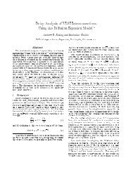
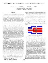
Figure 2 summarizes statistics <strong>for</strong> 64-sink clock subnets routed by<br />
Cadence Encounter DIS V10.1 [24]. The number of downstream<br />
loads (reflecting the average current) is highest near the source<br />
(driver) buffer, but rapidly decreases <strong>for</strong> the overwhelming majority<br />
of the clock subnet wirelength. Thus, there is no (electromigrationreliability)<br />
reason <strong>for</strong> a 2W or 3W NDR to persist <strong>for</strong> the entire<br />
routing topology of a given clock subnet.<br />
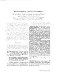
ogy used to generate the figure are from a public-domain 32/28nm<br />
PDK [26]; 32X buffers are used <strong>for</strong> driver and sinks. In this case,<br />
application of the SNDR can reduce wire capacitance by 27% “<strong>for</strong><br />
free” - that is, with zero decrease in maximum driven wirelength, at<br />
r = 0.9. Alternatively, wire capacitance can be reduced by 34% at<br />
the cost of 5% decrease in maximum driven wirelength, at r = 1.0.<br />
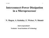
With the above studies as our starting point, we explore the dichotomy<br />
between today’s fixed NDR methodology and a possible<br />
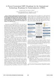
smart NDR methodology. The cartoon of Figure 4 shows that<br />
fixed NDRs on clock subnets result in larger driven capacitance,<br />
potentially leading to larger currents, larger drivers, and increased<br />
dynamic power. (Indeed, if the larger drivers violate signal EM<br />
limits, even the larger (wider) NDRs may be required.) By contrast,<br />
smart NDRs taper wire widths as the number of downstream loads<br />
decreases, reducing driven capacitance, dynamic power, and the<br />
number and size of buffers.<br />
larger<br />
capacitance<br />
smaller<br />
capacitance<br />
FixedNDR<br />
(wider wire)<br />
<strong>Smart</strong>NDR<br />
(tapering)<br />
fewer/smaller<br />
clock buffers, power<br />
more/larger<br />
buffers, power<br />
Figure 2: Study of 64-sink subnets routed by Cadence Encounter DIS V10.1 [24].<br />
Approximately 80% of clock subnet wirelength is in the lower levels of the tree,<br />
with few downstream loads and lower currents. The wire segment incident to the<br />
source has highest current but on average is only a small fraction of a subnet’s<br />
total wirelength.<br />
140%<br />
120%<br />
100%<br />
80%<br />
60%<br />
40%<br />
20%<br />
0%<br />
Maximum Wirelength<br />
Capacitance<br />
0 0.1 0.2 0.3 0.4 0.5 0.6 0.7 0.8 0.9 1<br />
SNDR Ratio (r = SNDR length / total length)<br />
(a)<br />
1-r<br />
r<br />
(b)<br />
3W3S<br />
1W4S<br />
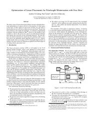
Figure 3: (a) Electrical per<strong>for</strong>mance when an equivalent-pitch SNDR (1W4S)<br />
is applied to a fraction r of a wire with a given original NDR (3W3S). Shown<br />
are maximum wirelength possible while satisfying a prescribed slew constraint,<br />
and total wire capacitance (both values normalized, and plotted against the y-<br />
axis). The ratio r = 0.9 achieves 27% capacitance reduction without incurring<br />
any reduction of maximum wirelength. (b) Illustration of tapering of wire from<br />
the original NDR (blue color) to the SNDR (red color). SPICE simulation is used<br />
to determine delay and slew with different SNDR ratios r.<br />
Further motivation is obtained from SPICE experiments that evaluate<br />
the potential <strong>for</strong> SNDR-based capacitance reduction without<br />
loss of electrical per<strong>for</strong>mance. We study a symmetric H-tree [1]<br />
with a large buffer as driver, and 16 identical buffers as sinks. We<br />
sweep an SNDR ratio, r (i.e., wirelength with a given SNDR, divided<br />
by total wirelength – see Figure 3 (b)), to observe the impacts<br />
of SNDR wire tapering from different fixed original NDR widths<br />
and spacings. We assume that the signal transition at the input pin<br />
of the driver cell has 50ps slew time, and we find the maximum<br />
wirelength which maintains the same slew time at the end of the<br />
wire (i.e., at sink input pins), as well as the corresponding total wire<br />
capacitance. 3 For example, Figure 3 shows maximum wirelength<br />
under the 50ps maximum slew time constraint, and wire capacitance<br />
(both values normalized and plotted against the y-axis), when<br />
a (1W4S) SNDR is applied to save capacitance from an equivalentpitch<br />
(3W3S) original NDR. The library and interconnect technol-<br />
3 Because the H-tree is symmetric, greater wirelength means that the sinks of the H-<br />
tree are spaced farther apart.<br />
EM violations<br />
Figure 4: Intuitive dichotomy between today’s “fixed NDR” methodology and a<br />
potential “smart NDR” methodology.<br />
This Work<br />
In this work, we assess the potential <strong>for</strong> capacitance and power<br />
reductions through use of “smart” NDRs (SNDRs) that substitute<br />
narrower-width NDRs <strong>for</strong> selected clock net segments while maintaining<br />
skew, slew, delay and EM reliability criteria. We <strong>for</strong>mulate<br />
the optimal application of SNDRs <strong>for</strong> a given clock subnet as a<br />
quadratically constrained program. We also demonstrate the practicality<br />
of a flow that applies SNDRs at the end of the CTS phase<br />
in a commercial place-and-route tool.<br />
The main contributions of our work are summarized as follows.<br />
• We per<strong>for</strong>m studies of practical clock routing instances and<br />
NDRs to establish the potential <strong>for</strong> substantial dynamic power<br />
reductions using SNDRs.<br />
• We <strong>for</strong>mulate optimal application of SNDRs as a quadratically<br />
constrained program to minimize wire capacitance under<br />
skew, slew, delay and EM constraints, and we efficiently<br />
solve this problem <strong>for</strong> each subnet of a given clock tree.<br />
• We extend our SNDR solution approach to the entire clock<br />
tree by propagating skew constraints from downstream subnets<br />
to upstream subnets.<br />
• We also propose a practical flow to apply SNDRs transparently<br />
post-CTS within a standard commercial place-and-route<br />
tool.<br />
• We empirically confirm an average of 16% clock wire capacitance<br />
reduction, and 5% total clock power reduction, achieved<br />
by our proposed technique, as compared to traditional CTS<br />
approaches with fixed NDRs.<br />
The remainder of this paper is organized as follows. In Section<br />
2, we give an overview of related literature. Section 3 <strong>for</strong>mulates<br />
the SNDR problem, and Section 4 describes our wire-tapering approach.<br />
Section 5 provides experimental results and analysis. We<br />
give conclusions and ongoing research directions in Section 6.