ORION EM G
ORION EM G
ORION EM G
- No tags were found...

Create successful ePaper yourself
Turn your PDF publications into a flip-book with our unique Google optimized e-Paper software.
<strong>ORION</strong><br />
<strong>EM</strong> G
----------------------------------------------<br />
ELECTRONIC MEASURING INSTRUMENTS<br />
GENERATORS<br />
ELECTRONIC VOLTMETERS AND AMMETERS<br />
DIGITAL VOLTMETERS AND FREQUENCY METERS<br />
OSCILLOSCOPES- -<br />
POWER SUPPLIES<br />
INDUSTRIAL MEASURING INSTRUMENTS<br />
ELECTRONIC MEDICAL TEST EQUIPMENTS<br />
ELECTRONIC LOGIC CIRCUITS<br />
ELECTRONIC DeSK CALCULATORS<br />
ELECTRONIC DIGITAL COMPUTERS<br />
This short catalogue contains a representative selection<br />
of <strong>EM</strong>G's-Works for Electronic Measuring Gearproducts.<br />
Owing to the numerous types of product<br />
only a few lines of technical data are provided on each<br />
type in this catalogue. The published informations in<br />
short form facilitate the choice of the most suitable<br />
instruments for the purpose of electronic measurements,<br />
medical examinations, processing control, data<br />
process, as well as arithmetical operations.<br />
If you require more detailed information than that<br />
covered by this catalogue, please let us know your<br />
specific interest. From any types or any groups we<br />
gladly send you the full technical details upon your<br />
request.<br />
For measurements, tests, calculations and control<br />
many electronic measuring inst-ruments, equipment<br />
are necessary in electronic, medical sciences, data processing<br />
as well as in a wide range of industrial applications.<br />
<strong>EM</strong>G developes and manufactures instruments<br />
widely used for the above purposes. Besides a quantity<br />
of products the factory every year developes and markets<br />
new instruments satisfying the most diverse<br />
requirements. Should the development of our products<br />
or the trend of our manufacturing program<br />
require it, we reserve the right to discontinue the<br />
production of some types described here or to deliver<br />
instead of them a later design.
ELECTRONIC MEASURING IHSTRUMEHTS•CiEHERATORS<br />
LOW-FREQUENCY GENERATORS<br />
<strong>EM</strong>G-1117/1 TR-0
O SCILLATORS A ND A F GENERAT ORS<br />
<strong>EM</strong>G-111-4 TR-0151 Transistor ized AF O scillato r<br />
The instrument is used for producing sinusoidal signals with very low distortion in t he<br />
audio-frequency range. It is fully transistorized and can be operated either from mains<br />
or from an external battery.<br />
Frequency range:<br />
Frequency accuracy:<br />
Output voltage:<br />
Distortion factor 200 cfs to 10 kcfs:<br />
Dimensions:<br />
20 cfs to 20 kc/s<br />
±1%±1 cjs<br />
0 to 4 V<br />
(into 600 ohms)<br />
~ 0.1%<br />
220x 180 x 295 mm<br />
<strong>EM</strong>G-11 H TR-0250 T ra nsistorized MF O scillator<br />
The instrument furnishes low distortion sinusoid al signals. It is full y transistorized<br />
and can be operated from mains or from an external battery.<br />
Frequency range:<br />
Frequency accuracy :<br />
Output voltage:<br />
Distortion factor 100 cfs to 200 kc 's :<br />
Dimensions :<br />
30 cjs to 550 kc/s<br />
±3%<br />
0 to 1.1 V<br />
(into 600 ohms)<br />
:s O,S%<br />
220 x 180 x 295 mm<br />
<strong>EM</strong>G-1 115 TR-0105 Au d io Frequency Gene rat o r<br />
The RC oscillator of the instrument supplies in<br />
the range of 20 and 20,000 cfs sinusoidal AF<br />
voltages. The generator incorporates an amplifier<br />
and a voltmeter.<br />
RC OSCILLATOR<br />
Frequency range:<br />
20 c/s to 20 kc1s<br />
Distortion factor : ~ 0.3%<br />
RC OSCILLATOR WITH AF AMPLIFIER<br />
Output power:<br />
max. 5 W<br />
Optimum load<br />
at asymmetrical output:<br />
at symmetrical output :<br />
Dimensions:<br />
5, 600, 5,000 ohms<br />
2x 300,<br />
2 x 2,500 ohms<br />
180 X 436 X 360 mm<br />
----<br />
<strong>EM</strong>G -1289 TR-0871 Pushbutton Decad e Generator<br />
The instrument provides low distortion sinusoidal signal. By means of the pushbuttonsystem<br />
4,500 discrete values can be selected in 5 decadic bands, with th ree significant<br />
figures in steps of 0.01 digit. The instrument is fu lly transistorized and can be operated<br />
from mains or from a built-in battery.<br />
Frequency range:<br />
Frequency accuracy 10 c/s to 99.9 kc ls·<br />
Distortion factor 100 cis to 20 kc s<br />
Output voltages<br />
Dimensions ·<br />
10 c/s to 1 Mc/s<br />
±1%<br />
4i0.5%<br />
0 to 2.5 V, 0.25 V.<br />
0.025 V, resp.<br />
(Into 600 ohms)<br />
220 x 230 x 270 mm
SIGNAL GENERATORS<br />
<strong>EM</strong>G -1165 TR-0550 Crystal-controlled Signal Generator<br />
The instrument furnishes calibrated HF signals which can be used either<br />
unmodulated or amplitude modu lated. Fully transistorized.<br />
Frequency range :<br />
Frequency accuracy :<br />
Frequency calibration:<br />
Output voltage :<br />
Modulation :<br />
Dimensions:<br />
100 kc/s to 30 Mc/s<br />
± 1%<br />
by means of a built-in<br />
1 Mc/s<br />
quartz oscillator<br />
0.5 .uV to 100 mY<br />
{int~ 50 ohms)<br />
internal AM<br />
(400 or 1,000 cfs)<br />
external AM<br />
200x260x280 mm<br />
<strong>EM</strong>G-1168 TR-0503 Crystal-controlled Laboratory Signal Generator<br />
This is a high-accuracy signal generator operating in the 50 kcfs to<br />
65 Mcfs frequency range. By means of the built-in crystal oscillator hig h<br />
accuracy of frequency calibration can be obtained.<br />
Frequency range:<br />
SO kcfs to 6S Mc/s<br />
Frequency accuracy: ± 1%<br />
Frequency calibration :<br />
Output voltage:<br />
Modulation:<br />
Dimensions:<br />
by means of a built-in<br />
quartz oscillator with<br />
10- • accuracy<br />
0. 1 '! V to 3 V<br />
{into SO ohms)<br />
internal AM<br />
(400 or 1,000 cis)<br />
external AM<br />
300 X 500 X 380 mm<br />
<strong>EM</strong>G-1173 /2 TR-0604 VHF Signal Generator {AM-FM<br />
Video-Stereo)<br />
:<br />
The instr ument can be used in almost al l fields of telecommunication<br />
engineering where in the frequency range of 4 to<br />
300 Mc/s an AM , FM, video-, stereo-, or pulse modulated highly<br />
accurate H F sig nal source is needed.<br />
Frequency range:<br />
Frequency accuracy :<br />
Output vo ltage:<br />
Modulation·<br />
Dimensions :<br />
4 to 300 Mc fs<br />
± 1%<br />
0.5 iJ.V to 100 mV .<br />
0.5 iJ.V to 1 V,<br />
resp.<br />
internal.<br />
exter nal AM ,<br />
internal ,<br />
external FM ,<br />
video, stereo, pu lse<br />
317 X S70 X 340 mm<br />
<strong>EM</strong> G-11 75 /2 TR-0602 UHF Signal Generator<br />
Owing to its wide modu lation and other control faci li ties, the<br />
instrument can be used for performing a variety of UH F measurements.<br />
Frequency range :<br />
Frequency accuracy:<br />
Output voltage :<br />
Modulation:<br />
Dimensions :<br />
250 to 1,000 Mcfs<br />
± 1%<br />
O.S iJ.V to 100 mV,<br />
0.5 (J.V to 4 V,<br />
resp.<br />
internal square wave,<br />
internal,<br />
external AM.<br />
internal.<br />
external FM,<br />
external video, pulse<br />
330 x 580 x 380 mm
<strong>EM</strong>G -1176/B TZA-101-B<br />
<strong>EM</strong>G-1177<br />
TZA-102<br />
~<br />
_ -<br />
...<br />
Q) (J<br />
..........<br />
~<br />
--<br />
g<br />
~<br />
-<br />
~<br />
<strong>EM</strong>G-1178 TZA-103 Microwave Signal Gener·<br />
a tors<br />
The instruments are suitable for all low-power<br />
microwave measurements.<br />
Frequency range<br />
<strong>EM</strong>G-1176/ B:<br />
<strong>EM</strong>G-1177 :<br />
<strong>EM</strong>G-1178 :<br />
Frequency accuracy:<br />
Output power:<br />
Modulation:<br />
Dimensions :<br />
1,800 to ~.000 Mcfs<br />
3,800 to 7,500 Mcfs<br />
7,000 to 10,500 Mcfs<br />
± 1%<br />
min. 1 mW<br />
(50 ohms)<br />
internal,<br />
external pulse,<br />
internal,<br />
external FM,<br />
internal square wave<br />
400x610x330 mm<br />
<strong>EM</strong>G-1175/ 3 TR-0603 UHF Signal Gener:ator<br />
Frequency range:<br />
Frequency accuracy :<br />
Output power:<br />
Modul~tion :<br />
Dimensions:<br />
<strong>EM</strong>G-1274 TR-0610 UHF Power Generator<br />
Frequency range:<br />
- •• Frequency accu racy :<br />
Max. output power:<br />
• ......<br />
Owing to Its wide modulation and other control facilities<br />
the instrument can be used for performing a variety of<br />
UHF measurements.<br />
1,000 to 2,500 Mcfs<br />
±1%<br />
min. 1 mW<br />
(50 ohms)<br />
internal,<br />
external pulse,<br />
internal,<br />
external FM,<br />
internal square wave<br />
400 X 500 x 380 mm<br />
The instrument is suitable for producing calibrated highlevel<br />
signals in the ultra-high frequency range of 250 to<br />
1,000 Mcfs.<br />
Modulation:<br />
Dimensions :<br />
250 to 1,000 Mc/s<br />
±1%<br />
min. 2 W<br />
(50 ohms)<br />
internal square wave,<br />
external pulse<br />
320 x 570x390 mm
CO!-OR TV GENERATORS<br />
<strong>EM</strong>G-1265 TR-0869 Color TV Tester<br />
The instrument is suitable for testing SECAM sets, its<br />
test signals have been designed accordingly: color purity<br />
and convergence signals serving for the adjustment of<br />
color picture tube, gray scale signal, testing signals serving<br />
for the measurement of color demodulator and identifying<br />
circuit. The instrument provides also signals on the VHF<br />
carrier frequency according to the OIRT channel I, in<br />
the required high level, supplemented with 1 kc/s AF<br />
modulation, for testing of the sound channel. Fully transistorized.<br />
·-· ·• ·<br />
..<br />
.. -<br />
•<br />
:=:<br />
COlOR TV TESTSI<br />
•<br />
-<br />
""' ~<br />
- ()<br />
L I ...<br />
•<br />
8 !<br />
--<br />
Dimensions:<br />
90x400x350 mm<br />
<strong>EM</strong>G-1266 TR-0870 Laboratory Color TV Generator<br />
·~.. .. ..<br />
~:P<br />
~!"' -·--<br />
The instrument serves for perfor·ming measurements<br />
and adjustments on SECAM TV sets. It<br />
consists of the video, synchron and oscillatormodulator<br />
un its. Since it furnishes signals with<br />
studio quality, it can be used primarily for laboratory<br />
measurements. The video unit provides video<br />
signals ; luminence signal, color scale signal, color<br />
identification signal, R.G.B. base signals, convergence<br />
signals produced from e ither an ex ternal<br />
signal source or internal signals. The synchron<br />
unit provides OIRT synchron and blanking signals.<br />
The oscillator-modulator unit furnishes VHF,<br />
UHF signals.<br />
Dimensions :<br />
222 X 435 x 400 mm<br />
MODULATION METER<br />
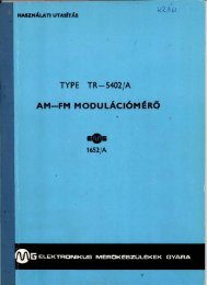
<strong>EM</strong>G-1651 TR-5401 AM-FM Modulation Meter<br />
The instrument is suitable for control measurements needed wi t h<br />
AM and FM systems operating in the 4 to 1,000 Mc/s frequency<br />
range.<br />
Carrier frequency range:<br />
with harmonic mixing:<br />
MEASUR<strong>EM</strong>ENT OF AM<br />
4 to 250 Mc/s<br />
250 to 1,000 Mc/s<br />
Measuring ranges of modulation percentage: 5, 15, 50, 100%<br />
Accuracy of modulation percentage<br />
measurement:<br />
MEASUR<strong>EM</strong>ENT OF FM<br />
Measuring ranges of FM<br />
deviation measurement:<br />
Accuracy of FM deviation measurement;<br />
Dimensions:<br />
±3%<br />
0.5; 1.5; 5; 15; 50;<br />
150 kc/s<br />
±2%<br />
300 X SOD X 380 mm
PRECISION SWEEP GENERATOR<br />
<strong>EM</strong>G-1 294 TR-0904 " SWEEPOSCOPE" Precision Sweep<br />
Generator<br />
The SWEEPOSCOPE is a combined instr ument serving for<br />
the calibration of active and passive two- and fou r-pole<br />
networks within the frequency range of 0.5 to 1,000 Mc{s.<br />
It comprises a transmitter, receiver and indicator unit. The<br />
transmitter unit is a high-stability sweep generator. It supplies<br />
H F signals with continuously adjustable deviation. Sweep<br />
frequency is SO cfs. The receiver unit contains diode detectors<br />
for the measurement of t he input and output signals of the<br />
object to be tested. The signals can be plotted on t he 36 em<br />
screen of the television picture-tube of an oscilloscope.<br />
Dimensions :<br />
440 x 580 x 400 mm<br />
BROADCAST TRANSMITTER TEST ASS<strong>EM</strong>BLY<br />
<strong>EM</strong> G-1189 TR-5601 Broa dcast Transmitter Test Assembly<br />
The equipment is suitable for making measurements of every essential qualitative and<br />
technical parameter of the radio broadcast t ransmitter. The following measu rements<br />
can be performed : harmon ic distortion (0 to 10%. with ±0.5% accuracy); modulation<br />
depth (0 to 100% . wit h ±5% accuracy): frequency deviation (0 to 75 kc/s. with ±5%<br />
accuracy); frequency response (in AM o r FM modes of operation, with ± 1 dB accuracy).<br />
noise level (up to - 56 dB): stability of the entire t ransmission channel (with ± 1 dB<br />
accuracy). By means of these measurements t he equipment facilitates a continuous<br />
monit oring of broadcast ing quality. The equipment consists of 13 plug-in units, which<br />
are the following : logometers (2 pc) ; FM receive rs (2 pc): deviation meters (2 pc) ;<br />
AM receiver: oscilloscope: AF generator; AM modulation meter and monitor line<br />
selector: automatic distortion, frequency response and noise level meter; swit ch,ng<br />
unit and sound monitor ing unit.<br />
Dimensions:<br />
2.000 x 600 x 500 m m
PULSE GENERATORS<br />
<strong>EM</strong>G-1153 TR-0353 Pulse Generator<br />
The instrument is a fully transistorized, small-size pulse generator. The<br />
pulse repetition rate, pulse width and delay can be regulated within -------::::::~;::.;;;:;~<br />
very wide limits. The amplitude of pulses of both polarities generated<br />
simultaneously can be adjusred separately.<br />
Pulse repetition rate :<br />
10 c{s to 2 Mc/s<br />
External triggering and single triggering facility provided<br />
Pulse delay :<br />
100 ns to 10 ms<br />
Pulse width :<br />
Amplitude:<br />
Polarity :<br />
Rise and fall time:<br />
Dimensions:<br />
100 ns co 10 ms<br />
max. 10 V<br />
(into 50 ohms)<br />
positive and negative,<br />
sim ultaneously<br />
.... 20 ns<br />
92 x 325x298 mm<br />
<strong>EM</strong>G-115"1 TR-0302 Laboratory Pulse, Double Pulse<br />
an d Square Wave Generator<br />
The instrument is a pulse generator suitable for laboratory<br />
measurements, in a wide field of applications. The repetit<br />
ion rate, pulse width, delay and amplitude of pulses of<br />
both polarities generated simultaneously can be adjusted<br />
separately.<br />
Pulse repet ition rate:<br />
0.1 c/s to 1 Mc/s<br />
Externa I triggering and single triggering facility provided<br />
Pulse width:<br />
100 ns to 11 ms<br />
Pulse delay:<br />
100 ns to 11 ms<br />
Pulse delay in double pulse<br />
mode of operation :<br />
200 ns to 11 ms<br />
Amplitude<br />
Z > 50 ohms output:<br />
10 V to 50 V<br />
50 ohms output:<br />
2 mV to 10 V<br />
Rise and fall time:<br />
25 ns<br />
Polarity:<br />
positive und negat ive,<br />
simultaneously<br />
Dimensions:<br />
445 X 500 X 380 mm<br />
<strong>EM</strong>G-1155 TR-0304 Pulse, Double Pulse and Square Wave<br />
Generator<br />
The instrument is a versatile pulse generator, most suitable for<br />
workshop measurements. The pulse repetition rate, pulse width<br />
and delay and the amplitude of pulses of both polarities generated<br />
simultaneously can be adjusted separately.<br />
Pulse repetition rate:<br />
c/s to 1 Mc/s<br />
External t riggering and single t riggering faci lity provided<br />
Pulse width :<br />
200 ns to 2 ms<br />
Pulse delay :<br />
200 ns to 2 ms<br />
Pulse delay in double pulse<br />
mode of operation :<br />
Amplitude<br />
Z> 50 ohms output:<br />
50 ohms output:<br />
Rise and fall time:<br />
Polarity:<br />
Dimensions:<br />
-400 ns to 2 ms<br />
2 V to 50 V<br />
2 mY to 2 V<br />
25 ns<br />
positive and negative,<br />
simultaneously<br />
265x500x 3BO mm
<strong>EM</strong>G -1157 TR-0354/5/6 Modular Pulse Generator<br />
The special design of the instrument renders possible the optional<br />
variation of two or more pulses. The circuits are interchangeable<br />
plug-in units. By assembling the available various units in different<br />
combinations it is possible to realize a generator with the technical<br />
characteristics best suited for the given pu r pose. The pulse<br />
repetition rate, delay, width and amplitude can be adjusted<br />
separately. The instrument is fully t ransistorized. Its units are<br />
the following:<br />
master generators<br />
delay units<br />
pulse output units<br />
attenuator units<br />
The plug-in units may be placed into a cabinet of<br />
rack-system. Each cabinet is capable of accommoda'ting<br />
6 units. The units may be interconnected through<br />
coaxial terminals located on their front or rear panels.<br />
More rack cabinets might be fitted together as well,<br />
thus the number of the modul units can be extended<br />
at will.<br />
Pulse repetition rate : 10 cfs to 2 Mcfs,<br />
20 kc/s to 20 Mc/s,<br />
resp.<br />
External triggering and single triggering facility provided<br />
Output pulses :<br />
Pulse width and delay:<br />
Polarity:<br />
Amplitude :<br />
Rise and fall t ime :<br />
Dimensions:<br />
one or more independent<br />
channels according<br />
to the configuration<br />
100 ns to 10 ms,<br />
10 ns to 20 !J.S,<br />
resp.<br />
positive and negative,<br />
simultaneously<br />
max. 10 V<br />
(into SO ohms)<br />
_,.:; 5 ns<br />
(typically 3 ns)<br />
177 X 436 X 195 mm<br />
Manufactured by <strong>EM</strong>G<br />
WORKS FOR .;LECTRONIC MEASURING GEAR<br />
Budapest XVI., Cziriky u. 26-32. HUNGARY<br />
Telex: 33-50.<br />
Exported by<br />
METRIMPEX<br />
HUNGARIAN FOREIGN TRADING COMPANY FOR INSTRUMENTS<br />
Budapest, 62. P.O .B. 2C2<br />
Cable: INSTRUMENT, Budapest, HUNGARY<br />
69.1417 E1yecemi Nyomda m"ynyomba, Budapett<br />
(Macyar Hirde
...._____.,._ EL_ECTRONIC VOLTMETERS AND AMMET_ER_S~____,<br />
ELECTRONIC VOLTMETERS FOR AC VOLTAGE MEASUR<strong>EM</strong>ENTS<br />
<strong>EM</strong>G-1314 TR-1103 V.T. Voltmeter<br />
The Instrument is a Y.T.Y.M., of a very stable amplifier system.<br />
It is used for measuring AC voltages between 5 mY and 300 V<br />
in the frequency range of 10 c/s to 1 Mcfs. It can also be used as<br />
a measuring amplifier.<br />
Measuring range :<br />
Measuring accuracy (at 1 kc/s):<br />
Frequency range :<br />
Frequency response<br />
(related to 1 kc/s)<br />
20 cfs to 300 kc/s:<br />
10 to 20 cfs, or<br />
300 to 1,000 kcfs, resp.:<br />
Dimensions :<br />
5 mY to 300 Y<br />
(in 9 ranges)<br />
±2% f.s.d.<br />
10 cfs to 1 Mcfs<br />
±2%<br />
<strong>EM</strong>G-1319 TR-1202 Sensitive V.T. Voltmeter<br />
±5%<br />
236 x 180 x 250 mm<br />
The Instrument is used for measuring symmetrical and asymmetrical<br />
AC voltages between 50 fLY and 300 Y in frequency range<br />
of 10 cfs to 1 Mcfs. It can also be used as a measuring amplifier.<br />
ASYMMETRICAL INPUT<br />
Measuring range:<br />
Measuring accuracy<br />
(at 1 kc/s):<br />
Frequency range :<br />
Frequency response<br />
(related to 1 kc/s)<br />
20 cfs to 300 kcfs :<br />
50 fLY to 300 V<br />
(in 13 ranges)<br />
± 2% f.s.d.<br />
10 cfs to 1 Mcfs<br />
± 2%<br />
10 to 20 cfs, or<br />
300 to 1,000 kc/s, resp.:<br />
SYMMETRICAL INPUT<br />
± S%<br />
Measuring range:<br />
SO !J.Y to 10 V<br />
Measuring accuracy:<br />
±3% f.s.d.<br />
Frequency range :<br />
60 cfs to 20 kc/s. or<br />
3 kcfs to 300 kc/s,<br />
resp.<br />
Dimensions:<br />
26S x 200 x 28S mm<br />
<strong>EM</strong>G-1322 TR-1204 Precision V.T . Voltmeter<br />
The instrument is a very accurate, high stability V.T. Voltmeter,<br />
which can be used for measuring AC voltages between SO fLY<br />
and 300 V in the frequency range of 10 cfs to 5 Mc/s. Owing to<br />
the high accuracy obtained, it is also suitable for laboratory<br />
precision measurements.<br />
Measuring range :<br />
Measuring accuracy<br />
(at 1 kcfs):<br />
Frequency range:<br />
Frequency response<br />
(related to 1 kc/s)<br />
50 cfs to SOO kcfs:<br />
20 to SO cfs, or<br />
SOO to 1,000 kcfs, resp.:<br />
10 to 20 cfs, or<br />
1 to 5 Mcfs, resp.:<br />
Dimensions :<br />
SO fLY to 300. Y<br />
(in 12 ranges)<br />
± 1% f.s.d.<br />
10 cfs to S Mcfs<br />
±1%<br />
±2%<br />
±5%<br />
26S x 200x28S mm<br />
<strong>EM</strong>G-1324 TR-1301 Wide Band V.T. Voltmeter<br />
The instrument Is designed for measuring low-level AC voltages over a<br />
wide frequency range. The signal to be measured reaches the measuring<br />
probe either directly, or at low-level signal measurement, through a<br />
pre-divider.<br />
Measuring range:<br />
Measuring accuracy :<br />
Frequency range :<br />
Frequency response<br />
(related to SO kc/s)<br />
1 kc/s to 10 Mcfs :<br />
10 Mcfs to 30 Mc/s :<br />
(without pre-divider)<br />
Dimensions:<br />
100 !J.Y to 30 Y<br />
(in 10 ranges)<br />
±3% f.s.d.<br />
1 kc/s to 30 Mcfs<br />
±S%<br />
±8%<br />
26S x 200 x 36S mm
<strong>EM</strong>G -1325 TR -1 351 RF Millivoltmeter<br />
The instrument is used for measuring AC voltages between 1 mV and 10 V in the<br />
frequency range of 0.5 to 1,000 Mcfs. The measuring range can be extended up to<br />
1,000 V by means of a divider. The RF measurements can be performed by means of<br />
several measuring probes. The instrument is fully transistorized.<br />
Measuring range:<br />
Frequency range:<br />
M easu ring accuracy<br />
0.5 to 50 Mcjs :<br />
50 to 150 Mcjs :<br />
150 to 1,000 Mcfs :<br />
Dim ensions:<br />
1 mV to 10 V<br />
(in 7 ranges)<br />
0.5 to 1,000 Mcfs<br />
±3% f.s.d.<br />
±6% f.s.d.<br />
±1 dB f.s.d.<br />
247 X 196 X 300 mm<br />
<strong>EM</strong>G-1353 TR-1453 Transistorized AC Voltmeter<br />
The instrument is used for measuring AC voltages between<br />
100 fi.V to 300 V in the frequency range of 1 cfs to 1 Mcfs. It is<br />
fully transistorized, small size, can be operated from battery.<br />
Measuring range:<br />
Measuring accuracy :<br />
Frequency range:<br />
Frequency response<br />
(related to 1 kcfs)<br />
5 cfs to 500 kcjs :<br />
1 to 5 cfs, or<br />
500 to 1,000 kc/s, resp.:<br />
Dimensions:<br />
DC AMMETER<br />
<strong>EM</strong>G-1J48 TR-1104 DC Milliammeter<br />
100 fi.Y to 300 V<br />
(in 12 ranges)<br />
±3% f.s.d.<br />
1 cjs to 1 Mcjs<br />
±3%<br />
±5%<br />
165 x 180 x1 10 mm<br />
The instrument can be used for measuring DC in the range of<br />
0 .3 mA to 1 A. The current can be measured without breaking<br />
the circuit, by means of a measuring probe damped on the<br />
conductor.<br />
Measuring range:<br />
Measuring accuracy:<br />
Dimensions :<br />
0.3 rnA to 1 A<br />
(in 6 ranges)<br />
± 3% f.s.d.<br />
236 x 180 x 320 mm<br />
DC VOLTMETER-AMMETER<br />
<strong>EM</strong>G-1352 TR-1452 DC Microvolt-Ammeter<br />
The instrument is suitable for measu ring very low positive and<br />
negative DC voltages and currents. It can be used as a DC<br />
amplifier.<br />
VOLTAGE MEASUR<strong>EM</strong>ENT<br />
Measuring range:<br />
Measuring accuracy :<br />
CURRENT MEASUR<strong>EM</strong>ENT<br />
Measuring range :<br />
Measuring accu racy:<br />
Dimensions:<br />
1 t,J.Y to 1 V (±)<br />
±3% f.s.d.<br />
1 pA to 3 rnA (±)<br />
±3% f.s.d.<br />
247 x 196 x 300 mm
ELECTRONIC VOLTMETERS FOR AC, DC VOLTAGE AND RESISTANCE MEASUR<strong>EM</strong>ENTS<br />
<strong>EM</strong>G-1341 / E TR-1401-E " ORIVOHM II" Workshop V.T. Voltmeter<br />
The instrument is an easily operated V.T. Voltmeter of dependable<br />
construction, designed for measuring DC and AC voltages as well as<br />
resistances.<br />
DC VOLTAGE MEASUR<strong>EM</strong>ENT:<br />
Measuring accuracy:<br />
AC VOLTAGE MEASUR<strong>EM</strong>ENT:<br />
Measuring accuracy :<br />
Frequency range:<br />
RESISTANCE MEASUR<strong>EM</strong>ENT:<br />
Measuring accuracy:<br />
Dimensions:<br />
100 mY to 1,000 V<br />
±3% f.s.d.<br />
200 mY to 300 V<br />
±5% f.s.d.<br />
30 cfs to 25 Mcfs<br />
0.2 ohm<br />
to 1,000 Mohms<br />
±5% at mid-scale<br />
180 x236x145 mm<br />
<strong>EM</strong>G-1344 TR-1405 Voltage, Resistance Meter (HT and HF)<br />
The instrument is used for measuring DC and AC voltages as well as<br />
resistances. With a separate HT measuring probe DC voltages up to<br />
30 kV and by means of the HF measuring probe AC voltages up t o<br />
700 Mc/s can be measured.<br />
DC VOLTAGE MEASUR<strong>EM</strong>ENT :<br />
Measuring accuracy:<br />
With the HT probe:<br />
AC VOLTAGE MEASUR<strong>EM</strong>ENT :<br />
Measuring accuracy:<br />
Frequency range:<br />
With the H F probe :<br />
RESISTANCE MEASUR<strong>EM</strong>ENT :<br />
Measuring accuracy :<br />
Dimensions:<br />
20 mY to 1,000 V<br />
± 3% f.s.d .<br />
up to 30 kV<br />
100 mY to 300 V<br />
± 5% f.s.d.<br />
30 cfs to 5 Mcfs<br />
1 kcfs to 700 Mcfs<br />
0 .2 ohm<br />
to 1,000 Mohms<br />
±5% at mid-scale<br />
180 x 236 x 145 mm<br />
<strong>EM</strong>G-1345 TR-1406 Electronic Multimeter<br />
The instrument is an easily operated V.T. Voltmeter, designed for<br />
measuring DC and AC voltages, DC currents as well as resistances. HT<br />
and HF measuring probes can also be used with the instrument.<br />
DC VOLTAGE MEASUR<strong>EM</strong>ENT :<br />
Measur ing accuracy:<br />
With the HT probe:<br />
AC VOLTAGE MEASUR<strong>EM</strong>ENT :<br />
Measu ring accuracy:<br />
Frequency range:<br />
With the H F probe:<br />
RESISTANCE MEASUR<strong>EM</strong>ENT:<br />
Measuring accuracy:<br />
DC MEASUR<strong>EM</strong>ENT :<br />
Dimensions:<br />
20 mV to 1,000 V<br />
± 2.5% f.s:d.<br />
up to 30 kV<br />
100 mV to 300 V<br />
± 3% f.s.d.<br />
30 cfs to 5 Mcfs<br />
10 kc/s to 700 Mcfs<br />
0.2 ohm<br />
to 1,000 Mohms<br />
±5% at mid-scale<br />
0.1 rnA<br />
to 1,000 rnA<br />
220x 180 x 210 mm<br />
<strong>EM</strong>G-1346 TR-1407 "TRANSORIVOHM" Universal Voltmeter<br />
It is an easy handling, safe operation, fu lly transistorized universal V.T.<br />
voltmeter. By means of the instrument DC and AC voltages as well as<br />
resistances can be measured.<br />
DC VOLTAGE MEASUR<strong>EM</strong>ENT :<br />
Measuring accuracy:<br />
AC VOLTAGE MEASUR<strong>EM</strong>ENT:<br />
Measuring accuracy:<br />
Frequency range:<br />
RESISTANCE MEASUR<strong>EM</strong>ENT :<br />
Measuring accuracy :<br />
Dimensions:<br />
10 mV to 1,000 V<br />
± 2% f.s.d.<br />
1 mV to 300 V<br />
±3% f.s.d.<br />
10 cfs to 1 Mcfs<br />
1 ohm to 50 Mohms<br />
± 5% at mid-scale<br />
131 x 180 x 174 mm
-·- --<br />
•<br />
MEASURING AMPLIFIERS ~·<br />
<strong>EM</strong>G-1375 TR-1205 High-gain DC Amplifier<br />
The instrument can be used together with the plug-in amplifier<br />
unit <strong>EM</strong>G-1589-U-11 as measuring amplifier. Its high zero point<br />
stability makes it suitable for the amplification of DC voltages<br />
in the order of 50-100 ;;.V.<br />
Amplification:<br />
Accuracy of input attenuator:<br />
Frequency range:<br />
Linear distortion<br />
(related to 1 kc/s):<br />
Zero point stability<br />
(related to input) :<br />
Output voltage:<br />
Dimensions:<br />
20,000 to 0.04<br />
(in 18 bands)<br />
±2%<br />
DC to 250 kc{s<br />
(can be switched over<br />
in 5 steps)<br />
± 3 dB<br />
25 ;;.V /hour<br />
max. ±15 V DC or<br />
max. 10 Yrms<br />
290 x 200 x 433 mm<br />
<strong>EM</strong>G-1376 TR-1206 AC Measuring Amplifier<br />
The instrument serves for the amplification of low AC voltages<br />
over a wide frequency range.<br />
Amplification:<br />
Accuracy of amplification<br />
(at 1 kc/s):<br />
Frequency range:<br />
Linear distortion<br />
(related to 1 kc/s)<br />
20 cfs to 1 Mcfs:<br />
10 to 20 cfs, or<br />
1 to 5 Mcfs, resp.:<br />
Output voltage:<br />
Dimensions:<br />
max. 60 dB<br />
(in 6 steps)<br />
±0.5 dB<br />
10 cfs to 5 Mcfs<br />
±0.5 dB<br />
±1 dB<br />
max. 2 V<br />
265 >q_OO x 285 mm<br />
MICROWAVE POWER METERS<br />
<strong>EM</strong>G-1383 TZA-353 Transistorized Microwave Power Meter<br />
The fully transistorized instrument, together with the thermistor<br />
measuring probe, which can be connected to it, is used to measure<br />
H F or microwave power.<br />
Measuring range:<br />
Measuring accuracy:<br />
Frequency range<br />
(with measuring probe <strong>EM</strong>G-1383 /5):<br />
Dimensions:<br />
0.01 to 10 mW<br />
(in 5 ranges)<br />
± 5% f.s.d.<br />
10 Mcfs to 10 Gcfs<br />
236 x 180 x 145 mm<br />
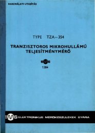
<strong>EM</strong>G-1384 TZA-354 Transistorized Microwave Power Meter<br />
(temperature compensated)<br />
Combined with the temperature compensated thermistor measuring<br />
probe, the instrument is suitable for measuring HF and<br />
microwave power. Fully transistorized.<br />
Measuring range:<br />
Measuring accuracy:<br />
Frequency range<br />
(with measuring probe<br />
Dimensions:<br />
<strong>EM</strong> G-1384/5):<br />
1 u.W to 10 mW<br />
( i~ 7 ranges)<br />
±5% f.s.d.<br />
10 Mcfs to 10 Gcfs<br />
250x190x330 mm<br />
s<br />
METRIMPEX<br />
HUNGARIAN FOREIGN TRADING COMPANY FOR INSTRUMENTS 0 R I 0 N ( . . ) E M G<br />
Budapest, 62. P.O.B. 202 ,<br />
Cable: INSTRUMENT, Budapest, HUNGARY<br />
Manufactured by <strong>EM</strong>G<br />
WORKS FOR ELECTRONIC MEASURING GEAR<br />
Budapest, XVI., Cziriky u. 26-32. HUNGARY<br />
Telex: 33-50.<br />
Exported by<br />
69.1417 qyetemi Nyomda m61ynyomlsa, Budapest<br />
(Manar Hirdec6)
DIGITAL VOLTMETERS AND FREQUENCY METERS<br />
DIGITAL VOLTMETERS AND CONVERTERS<br />
<strong>EM</strong>G-1361 TR-1651 Digital DC Voltmeter<br />
The instrument has been designed to measure DC voltages<br />
within a voltage range of 100 fJ.V to 1,000 V with 0.1% accuracy.<br />
The measured result is displayed by four in-line numerical<br />
indicator tubes.<br />
Measuring range:<br />
Upper limits of measuring ranges :<br />
Measuring accuracy :<br />
Period time of one measurement:<br />
Dimensions:<br />
100 !J.Y to 1,000 V<br />
(in 5 ranges)<br />
0.1599 v. 1.599 v.<br />
15.99 v. 159.9 v.<br />
1,000 v<br />
±0.1% of f.s.<br />
280 ms<br />
240x500x380 mm<br />
<strong>EM</strong>G-1365 TR-1753 ResistancefDC Converter<br />
Connected to the <strong>EM</strong>G-1361 Digital DC Voltmeter, the instrument<br />
is suitable for the accurate measurement of ohmic resitances<br />
in a wide range.<br />
Measuring range:<br />
Measuring accuracy :<br />
Dimensions:<br />
0.1 ohm to 10 Mohms<br />
(in 6 ranges)<br />
±0.2% of f.s .<br />
190 x500x380 mm<br />
<strong>EM</strong>G-1367 TR-1751 ACfDC Converter<br />
Connected to the <strong>EM</strong>G-1361 Digital DC Voltmeter, the instrument<br />
is suitable for high accuracy measurement of AC voltages.<br />
Measuring range:<br />
Frequency range:<br />
Measuring accuracy<br />
50 cfs to 50 kcfs:<br />
20 to 50 cfs, or<br />
50 to 500 kcfs, resp. :<br />
Dimensions:<br />
50 uV to 300 V<br />
(in '10 ranges)<br />
20 cfs to 500 kcfs<br />
±0.5% of f.s.<br />
±2.5 of f.s.<br />
150x500x380 mm<br />
<strong>EM</strong>G -1362 TR-1652 Digital DC Voltmeter<br />
The instrument is a four-digit digital DC Voltmeter with h1gh<br />
accuracy and high sensitivity.<br />
Measuring range:<br />
Upper limits of measuring ranges:<br />
Range selection :<br />
Measuring accuracy :<br />
Period time of one measurement:<br />
Dimensions :<br />
20 u.V to 1,000 V<br />
(in 's ranges)<br />
0.19998 v. 1.9999 v.<br />
19.999 v. 199.99 v.<br />
1,000 v<br />
manual or automatic<br />
± 0.01%<br />
± 1 digit of f.s.<br />
20 ms<br />
240 x 500 X 390 mm<br />
<strong>EM</strong>G-1368 TR -1752 AC/ DC Converter<br />
Connect.ed to the <strong>EM</strong>G-1362 Digital DC Voltmeter, the instrument<br />
is suitable for high accuracy measurement of AC voltages.<br />
Measuring range:<br />
Frequency range :<br />
Measuring accuracy:<br />
(in' ranges of 2, 20, 200 V,<br />
between 30 cfs and 2.5 kc/s)<br />
Dimensions:<br />
0.2 mY to 200 Y<br />
(in 4 ranges)<br />
30 cfs to 10 kcfs<br />
±0.04% of f.s.,<br />
±0.05% of reading<br />
120 x 440 x 400 mm<br />
i/j.
<strong>EM</strong>G-1363 TR-1653 Integrating Digital DC Voltmeter<br />
The instrument has been designed for measuring DC voltages<br />
within a very wide voltage range (10 !J.Y to 1,000 V) with 0.05%<br />
accuracy. The measurement result is displayed by four in-line<br />
numerical indicator tubes. The application of integrating technics<br />
ensures efficient common mode rejection.<br />
Measu ri ng range:<br />
Measuring ranges:<br />
Measuring accuracy:<br />
Period time of one measurement:<br />
Dimensions:<br />
10 !J.Y to 1,000 V<br />
(in 6 ranges)<br />
20, 200 mY,<br />
2, 20, 200, 1,000 v<br />
±0.05%<br />
± 1 digit of f.s.<br />
30 ms<br />
135 x440x375 mm<br />
<strong>EM</strong>G-1366 TR-1754 ACJDC and ResistancefDC Converter<br />
Connected to the <strong>EM</strong>G-1363 Integrating Digital DC Voltmeter,<br />
the instrument is suitable for high accuracy measurement of AC<br />
voltages as well as resistances.<br />
AC VOLTAGE MEASUR<strong>EM</strong>ENT<br />
Measuring range :<br />
Measuring accuracy<br />
50 cfs to 50 kc/s:<br />
20 cfs to 500 kc/s:<br />
RESISTANCE MEASUR<strong>EM</strong> ENT<br />
Measurement range:<br />
Measuring accuracy<br />
200 ohms to 2 Mohms :<br />
2 Mohms to 20 Mohms :<br />
Dimensions:<br />
100 !J.V to 200 V<br />
(in 5 ranges)<br />
± 0.5% of f.s.<br />
±2% of f.s.<br />
0.1 ohm to 20 Mohms<br />
(in 6 ran~es)<br />
± 0 . ~% of f.s.<br />
±0.5% of f.s.<br />
90 x 440 x 430 mm<br />
"' 4 ~;<br />
I<br />
c; c<br />
TfPf , __<br />
DlGIUL MULTIIHTft<br />
<strong>EM</strong>G-1364 TR-1654 Digital Multimeter<br />
The instrument can be used for fast and accurate measurement<br />
of AC and DC voltages as well as resistances. The measured result<br />
is displayed by four in-line numerical indicator tubes.<br />
DC VOLTAGE MEASUR<strong>EM</strong>ENT<br />
Measuring range:<br />
Measuring ranges:<br />
Measuring accuracy :<br />
Period t ime of one measurement:<br />
AC VOLTAGE MEASUR<strong>EM</strong>ENT<br />
Measuring range:<br />
Measuring accuracy:<br />
Frequency range:<br />
RESISTANCE MEASUR<strong>EM</strong>ENT<br />
Measuring range:<br />
Measuring accuracy :<br />
Dimensions:<br />
2 mY to 500 V<br />
(in 3 ranges)<br />
5, 50, 500 v<br />
± 0.2% ±2 digits<br />
300 ms<br />
2 mY to 300 V<br />
(in 3 ranges)<br />
± 0.2%±2 digits<br />
40 cfs t o 10 kc/s<br />
2 o hms to 500 kohm s<br />
(in 3 ranges)<br />
± 0.5%± 2 digits<br />
107 x 265 x 310 mm<br />
<strong>EM</strong>G-1369 TR-2251 Digital Resistance Meter<br />
The instrument is used for highly accurate measurement of<br />
resistances. The measured result appears on five in-line numerical<br />
indicator tubes.<br />
Measuring range:<br />
Measuring accuracy:<br />
Measuring time:<br />
DImensions:<br />
5 mohms<br />
to 200 Mohms<br />
(in 8 ranges)<br />
±0.04% of f.s.<br />
380 ms<br />
180x436x360 mm
DIGITAL FREQUENCY· AND TIME METERS<br />
<strong>EM</strong>G-1645 TR-5250 Digital Frequency- and Time Meter<br />
The instrument is designed primarily for laboratory purpos~s.<br />
for the measurement of frequency, period time, average period<br />
time, pulse width, time interval and frequency ratio. It can al~o<br />
be used the totalizing count. The measured result appears on<br />
seven in-line numerical indicator tubes.<br />
Frequency measurement:<br />
Totalizing counting:<br />
Period time measurement:<br />
Average period time measurement:<br />
Pulse width measurement:<br />
Time interval measurement:<br />
0 to 10 Mcfs<br />
max. 10 7 pulse<br />
0 to 1 Mcfs<br />
(measurable shortest<br />
time 1 f.LS)<br />
10° to 10 7 periods<br />
measurable shortest<br />
pulse 1 f.LS<br />
measurable shortest<br />
time interval 1 f.LS<br />
100 mVrms<br />
Sensitivity:<br />
Stability of built-in time base generator: 1.10- 7 fweek,<br />
Dimensions:<br />
5. 10- 8 /day<br />
HOx500x380 mm<br />
<strong>EM</strong>G-1647 TR-5301 Frequency Range Extender for 10 Mc/s<br />
Counter/Frequency Meter<br />
Connected to the <strong>EM</strong>G-1645 Digital Frequency- and Time Meter,<br />
the instrument can be used to extend the basic frequency range.<br />
It can be operated with two types of converter units.<br />
WITH <strong>EM</strong>G-1689-U-91 CONVERTER UNIT (TR-5302)<br />
Frequency range:<br />
10 Mcfs to 100 M cfs<br />
Sensitivity:<br />
20 mVrms<br />
WITH <strong>EM</strong>G-1689-U-92 CONVERTER UNIT (TR-5303)<br />
Frequency range:<br />
100 Mc/s to 220 Mc/s<br />
Sensitivity:<br />
100 mVrms<br />
Dimensions:<br />
190 x 500 x 380 mm<br />
<strong>EM</strong>G-1642 TR-5252 Digital Frequency- and Time Meter<br />
The instrument is used for the measurement of frequency,<br />
frequency ratio, period time, average period time, time Interval<br />
as well as totalizing count. The measured result appears on six<br />
in-l ine numerical indicator tubes.<br />
Frequency measurement:<br />
Average period time measurement:<br />
Time interval measurement:<br />
Totalizing counting:<br />
Sensitivity:<br />
Stabilit y of the built-in crystal<br />
Dimensions:<br />
1 c/s to 1.2 Mcfs<br />
1 c/s to 1.2 Mcfs,<br />
10° to 10 5 period<br />
1 f.LS to 108 s<br />
1 cfs to 1,2 Mcfs<br />
100 mVrms<br />
oscillator: 1.10- 6 /day<br />
165x440x440 mrn
<strong>EM</strong>G-1643 Digital Frequency· and Time Meter<br />
DFT MfiU rm 11<br />
5 (' r, ..<br />
; (. ' '<br />
The instrument is used for the measurement of frequency,<br />
frequency ratio, period time, average period time, totalizing<br />
time interval, totalizing count. The portable instrument contains<br />
only silicon transistors and is characterized by low weight and<br />
small size. It can be used for industrial and laboratory measurements.<br />
Frequency measurement:<br />
Period time measurement:<br />
Totalizing counting:<br />
Input voltage<br />
(i n case of sinusoidal signal) :<br />
Time interval and totalizing<br />
t ime interval measurement:<br />
Frequency ratio measurement:<br />
Operating temperature range:<br />
Change of reference frequency<br />
{between 0 °C and +SO 0 C) :<br />
Dimensions:<br />
c fs to 1.S Mcfs<br />
s to 10 f.'S<br />
cf s to 1.5 Mc/s<br />
200 mVrms to 1SO Yrms<br />
10 IJ.S to 9999 s<br />
fA= 1 cfs to 1.5 Mcfs<br />
fs=O to 100 kc/s<br />
0 °C to +SO °C<br />
max. 8.10- 5<br />
107x 26S x 212 mm<br />
<strong>EM</strong>G-1646 Digital Frequency- and Time Meter<br />
The basic instrument type <strong>EM</strong>G-1646 can be used to measure<br />
frequency in the range of 0 to 100 Mc fs, with the Frequency<br />
Converter plug-in unit type <strong>EM</strong>G-1689-U-82 the instrument<br />
can be used for frequency measurements up to 3,1 Gcfs. At time<br />
measurements the resolution of the instrument is 10 ns. The<br />
stability of the built-in time base generator is 5.10- 9 . The instrument<br />
is fully transistorized, the measured result appears on nine<br />
In-line numerical indicator tubes. A printer can be connected<br />
to the instrument, operated by a 4-line BCD code output signal.<br />
FREQUENCY MEASUR<strong>EM</strong>ENT<br />
Measuring range<br />
DC coupled input:<br />
AC coupled input:<br />
Gate time:<br />
PERIOD TIME MEASUR<strong>EM</strong>ENT<br />
Measuring range:<br />
At average period time measurement:<br />
Averaging factor :<br />
0 to 100 Mcfs<br />
100 cfs to 100 Mcfs<br />
1 f.'S to 10 s, can be<br />
adjusted in decadic<br />
steps<br />
0 to 1 Mc/s<br />
0 to 100 kc/s<br />
1 to 10 5 period,<br />
in decadic steps<br />
Frequency counted :<br />
OTHER DATA<br />
Sensitivity:<br />
Frequency of time base:<br />
Stability of time base:<br />
Dimensions:<br />
<strong>EM</strong>G-1689-U-82 Frequency Converter<br />
1 c/s to 100 Mcfs,<br />
in decadic steps<br />
(resolution in 10 ns)<br />
100 mV<br />
5 Mc/s<br />
5.10- 9<br />
177 x443 x 400 mm<br />
The Frequency Converter, as a plug-in unit, widens the field<br />
of application of the Digital Frequency and T ime Meter type<br />
<strong>EM</strong>G-1646. It ensures high-accuracy and high-resolution measurements<br />
in the frequency rangeof100 to 3100 Mcfs. It is fully<br />
transistorized .<br />
Frequency measurement:<br />
Sensitivity:<br />
Dimensions :<br />
100 to 3,100 Mc /s<br />
50 mV<br />
(100 to 2,500 Mcfs)<br />
100 mV<br />
(2,SOO to 3,100 Mcfs)<br />
160 x 120x210 mm<br />
1 0 0 0 0 0 p 0 ·Q ...<br />
I<br />
Manufactured by <strong>EM</strong>G<br />
WORKS FOR ELECTRONIC MEASURING GEAR<br />
Budapest XVI., Cziraky u. 26-32. HUNGARY<br />
Telex: 33-SO.<br />
Exported by<br />
METRIMPEX<br />
HUNGARIAN FOREIGN TRADING COMPANY FOR INSTRUMENTS<br />
Budapest, 62. P.O.B. 202<br />
Cable: INSTRUMENT, Budapest. HUNGARY<br />
" .2417 E1yetemi Nyomda m"yr.yomua, Buclap•t<br />
(Ma1yar Hlrdet6)
<strong>EM</strong>G-1539 TR-4103 Oscilloscope (hish sensitivity)<br />
The Ottilloscope is designed for testing low level signals very<br />
frequently encountered in the field of telecommunication engineering<br />
and measuring techniques. The vertical amplifier of<br />
the instrument is a plug-in unit.<br />
CATHODE-RAY TUBE:<br />
VERTICAL AMPLIFIER<br />
Technical data are determined<br />
HORIZONTAL AMPLIFIER<br />
Bandwidth:<br />
Sensitivity:<br />
TIME BASE GENERATOR<br />
Sweep rate:<br />
Dimensions:<br />
130 mm<br />
screen diameter<br />
by the particular plug-in unit<br />
DC to 300 kc/s<br />
200 mVfcm<br />
to 20 v;cm<br />
Its interchangeable plug-in units are the following :<br />
1 fJ.S/cm to 5 sfcm<br />
360 x 260 x 570 mm<br />
<strong>EM</strong>G-1589-U-13 TR-4708 HiJh·gain Differential Amplifier<br />
It makes the oscilloscope suitable to carry out industrial measurements<br />
as well. The plug-in units is provided with a differential<br />
input.<br />
Modes of operation:<br />
Bandwidth:<br />
Sensitivity:<br />
A, A-B, B input<br />
with AC, DC coupling<br />
DC to 300 kcfs<br />
1 mVtcm to 50 V /em<br />
<strong>EM</strong>G-1589-U-11 TR-4709 High-gain Amplifier<br />
It allows to increase the vertical sensitivity of the oscilloscope<br />
up to 100 fJ.Vfcm. The bandwidth can be changed over in five<br />
steps between 250 and 0.5 kcfs.<br />
Input connection:<br />
Frequency range:<br />
Sensitivity:<br />
DC, AC<br />
DC to 250 kc Is<br />
100 ;;.Vfcm<br />
to so v,cm<br />
HIGH FREQUENCY OSCILLOSCOPES<br />
<strong>EM</strong>G-1546 TR-
<strong>EM</strong>G-1552 TR-4602 Dual-beam HF Oscilloscope<br />
It is designed for the observation of electrical phenomena taking<br />
place over a wide frequency range. It is particularly useful for<br />
the examination of two time-connected phenomena, simultaneously.<br />
Its specification is identical with that of the oscilloscope<br />
type <strong>EM</strong>G -1546, but si nee it has two vertical deflection systems.<br />
it can accommodate two plug-in preamplifiers.<br />
The Interchangeable plug-in units of the oscilloscopes type<br />
<strong>EM</strong>G-1546 and <strong>EM</strong>G-1SS2 are the following:<br />
<strong>EM</strong>G-1S89-U-1 TR-4704 Wide-band DC Preamplifier<br />
Input connection :<br />
Bandwidth<br />
used in <strong>EM</strong>G-1546 :<br />
used in <strong>EM</strong>G-1SS2 :<br />
Sensitivity :<br />
DC, AC<br />
DC to 30 Mcfs<br />
DC to 25 Mc/s<br />
SO mY {em to 20 V {em<br />
<strong>EM</strong>G-1589-U-2 TR-'4705 Dual-trace DC Preamplifier<br />
Input connection :<br />
Modes of operation :<br />
Bandwidth :<br />
Sensitivity:<br />
DC, AC<br />
only channel A<br />
only channel B<br />
CHOPPED<br />
ALTERNATE<br />
both channels<br />
summarized<br />
DC to 20 Mc fs<br />
50 mY/em<br />
to 20 Vfcm<br />
CATHODE-RAY TUBE :<br />
130 mm<br />
screen diameter<br />
VERTICAL AM PLIFIER<br />
Technical data are determined by the particular plug-in unit<br />
HORIZONTAL AMPLIFIER<br />
Bandwidth:<br />
Sensitivity;<br />
"A" TIME BASE GENERATOR<br />
Sweep rate:<br />
"B" TIME BASE GENERATOR<br />
Sweep rate:<br />
DELAYED SWEEP:<br />
Dimensions;<br />
<strong>EM</strong>G-1549/1 TR-4-405 HF Oscilloscope<br />
DC to 250 kc/s<br />
200 mVfcm<br />
to 20 Vfcm<br />
2 sfcm to 0.05 iJ.s/cm<br />
1 sfcm to 2 fJ.S /c m<br />
10 S tO 1 !J.S<br />
-430 X 320 X 620 mm<br />
Its specifications are identical with that of the oscilloscope<br />
<strong>EM</strong>G-1549/2 but it has only one time base generator, thus delayed<br />
sweep is not possible.<br />
<strong>EM</strong>G-1589-U-3 TR--4706 High-gain Differential Preamplifier<br />
Modes of operation:<br />
Bandwidth<br />
in position 1 mVfcm:<br />
in position SO mY/em :<br />
Sensitivity:<br />
A, A-B, B input<br />
with DC, AC coupled<br />
DC to 250 kc/s<br />
DC to 1.5 Mc/s<br />
1 mV fcm<br />
to 50 Vfcm<br />
<strong>EM</strong>G -1589-U--4 TR-4710 Transistor Rise-time Measuring Unit<br />
It serves for the measurement of pulse transmission data of<br />
transistors.<br />
Pulse amplitude:<br />
0.05 to 10 V<br />
Co II ector current:<br />
0.5 to 100 mAfcm<br />
Rise-time representable on screen: min. 12 ns<br />
Collector voltage:<br />
1 to 15 V<br />
<strong>EM</strong>G-1549/2 TR-4404 HF Oscilloscope<br />
it can be used for the observation of fast signals in a wide frequency<br />
range. The plug-in preamplifier layout ensures a wide<br />
field of application. It consists of two internal time base genera·<br />
tors providing accurate and continuous delayed sweep.
The interchangeable plug-in units of the oscilloscopes type <strong>EM</strong>G -<br />
15-49/2 and <strong>EM</strong>G-15-4911 are the following:<br />
Ba'ldwidt h :<br />
Sensitivity :<br />
D:: to -45 Mcfs<br />
50 mV /em to 20 V fcm<br />
<strong>EM</strong>G-1589-U-21 TR -4712 Wide-band DC Preamplifier<br />
Input connect io n :<br />
Bandwidth :<br />
Sensitivity :<br />
DC. AC , G N D<br />
DC to 45 Mc/s<br />
SO mVfcm<br />
co 20 Vfcm<br />
<strong>EM</strong>G-1589-U-22 TR-4713 Dua l-trace DC Prea mplifier<br />
Input connectio n:<br />
Modes of operation:<br />
DC , AC, GND<br />
only channel A<br />
only channel B<br />
CHOPPED<br />
ALTE RNATE<br />
<strong>EM</strong>G -1589-U-23 T R-4714 Hi&h-&ain Differential Prea mplifier<br />
Modes of operation:<br />
Bandwidth :<br />
in position 1 mV /em:<br />
in position 50 mVfcm :<br />
Sensit ivity:<br />
A, A- B, B input,<br />
with AC, DC coupling<br />
DC to 250 kc/s<br />
DC to 1.5 Mcfs<br />
1 mVfcm to 50 Vfcm<br />
<strong>EM</strong>G-1589-U -24 T R-4715 Transistor Rise-t ime Measu ring<br />
Unit<br />
The pl ug-in unit se rves for t he measure ment of pu lse transmission<br />
dau of transistors.<br />
Pulse amplitude :<br />
0.05 to 10 V<br />
Collector current :<br />
0.5 to 100 mAfcm<br />
Rise time representable on the screen : min. 12 ns<br />
Collector voltage:<br />
1 to 15 V<br />
<strong>EM</strong>G-1589-'J-25 T R-4716 Four-trace DC Preamplifier<br />
Modes of operation (MODE) :<br />
Bandwidth:<br />
Sensitivity:<br />
DC NORM,<br />
AC NORM, OFF,<br />
AC INV, DC INV.<br />
A LTERNATE<br />
or CHO PPE D<br />
independent of the<br />
MODE switch<br />
DC to 20 Mcfs<br />
20 mV/cm to 10 Vfcm<br />
TRANSISTORIZED OSCILLOSCOPES<br />
<strong>EM</strong>G-1563 TR-4651 "TRANSISCOPE- M" O scillosco pe<br />
The fully t ransistorized, small size oscilloscope serves for t he<br />
observation of elect rical phenomena caking place over a w ide<br />
frequency range.<br />
CATHODE-RAY TU BE·<br />
70 mm<br />
screen diameter<br />
VERTICAL AMPLIFI ER<br />
AC, DC coupled<br />
Bandwidth:<br />
DC to 10 Mcfs<br />
Sensitivity:<br />
50 mY /div<br />
co 20 V /div<br />
HORI ZONTAL AMPLI FIER<br />
Bandwidt h :<br />
Sensitivity:<br />
TIM E BAS E GENERATOR<br />
Sweep rate:<br />
Dimensions:<br />
<strong>EM</strong>G-1565 TR-4652 " TRANSISCOPE-K"<br />
Oscilloscope<br />
(1 div:0.6 em)<br />
DC to 1 Mc/s<br />
min. 100 mV /div<br />
0.2 ;J.S/d iv<br />
co 0.5 sfdiv<br />
200 x 160 x 340 mm<br />
Low Frequenc y<br />
The oscilloscope can be used for testing low level signals very<br />
fre quent in the field of telecommunication engineeri ng and<br />
measuring techniques. It is a fully transistorized, small size<br />
oscilloscope.<br />
CATHODE-RAY TUBE :<br />
VERTICAL AMPLIFIER<br />
Modes of operat ion :<br />
Bandwidth :<br />
Sensitivity:<br />
HORI ZONTAL AMPLIFIER<br />
Bandwidth :<br />
Sensitivity :<br />
TIM E BASE GENERATOR<br />
Sweep rate ·<br />
Dimensions·<br />
70 m m<br />
scree n d iamete r<br />
with diff. in put<br />
A, A - B, B input,<br />
with AC, DC coupled<br />
DC to 300 kcfs ·<br />
1 mY /div to 10 V /d iv<br />
(1 di v= 0.6 em)<br />
DC to 300 kcfs<br />
min. 100 mV fdiv<br />
1 ;J.S /dlv to 0.5 sfdiv<br />
200 x 160 x 340 mm<br />
E,'1G-15S6 TR-4650 "TRANSISCOPE-D" D ual Trace Oscil·<br />
losco pe<br />
It is for the observation of ele ctrical phenomena t aking place<br />
over a wide frequency range. It is particularly useful for examining<br />
two time-connected phenomena simultaneously. The instrument<br />
is fu lly transistorized.<br />
CATHODE-RAY TUBE:<br />
10:> mm<br />
VERTICAL AM PLIFIER<br />
Input connection:<br />
Modes of operation:<br />
Bandwidt h :<br />
Sensitivity:<br />
HORIZONTAL AMPLIFIER<br />
Bandwidth :<br />
Sensitivity:<br />
TIME BAS E G EN ERATOR<br />
Sweep rate:<br />
Dimensions:<br />
screen diameter<br />
DC, AC, GND<br />
CH1 only<br />
CH2 only<br />
dual trace CHO PPED<br />
dual t race<br />
ALTERNATE<br />
DC to 20 Mcfs<br />
50 mVjcm<br />
to 20 Vfcm<br />
DC to 1 Mcfs<br />
min. 100 mVfcm<br />
0.2 ;J.S/Cm<br />
to 0.5 sfcm<br />
255 x 200 x 385 mm
CHARACTERISTIC CURVE TRACER<br />
<strong>EM</strong>G-1 579 TR-4802, 4803 Characteristic Curve Tracer<br />
The instrument serves to measure quickly the parameters of<br />
several circuit components. The characteristic curves of components<br />
to be tested appear on the screen of a cathode-ray tube.<br />
The instrument is suitable fo r accommodating two plug-in units.<br />
The plug-in units are the following:<br />
Amplifier and Tolerance unit <strong>EM</strong>G-1579-U-71;<br />
Transistor and Diode Test unit <strong>EM</strong>G-1579-U-72;<br />
Electron Tube Test unit <strong>EM</strong> G-1579-l,J-73.<br />
With these plug-in units the instrument aan be used two different<br />
operating modes.<br />
<strong>EM</strong>G-1579-102 (TR-4802) (with U-71, U-72 units) for the testing<br />
of resistances, VD R resistances, tliodes, Zener diodes and transistors.<br />
<strong>EM</strong>G-1579-103 (TR-4803) (with U-71, U-73 units) for the testing<br />
of resistances, VDR resistances, diodes, Zener diodes, electron<br />
tubes and Nuvistors. Simultaneously, two components can be<br />
tested (reference and tested). The built-in step-generator facilitates<br />
the simultaneous checking of curves corresponding to<br />
several parameters.<br />
Useful picture area:<br />
Dimensions:<br />
8x8 em<br />
220 x 437 x 460 mm<br />
number of steps w hich can be plotted :<br />
Horizontal deflection<br />
measuring collector sweep voltage :<br />
measuring base sweep voltage ·<br />
Vertical deflection:<br />
4 to 10<br />
0 to 50 Vfdiv<br />
0 to 0.2 Vfdiv<br />
0 to 1 A/ div<br />
<strong>EM</strong>G -1S79-U-71 TR-4717 Amplifier and Tolerance unit<br />
It facilitates the adjustment of the tolerance field of the reference<br />
characteristic.<br />
Positive tolerance limits:<br />
0-5-10-20-50-100~<br />
Negative tolerance limits:<br />
0-5-10-20-50~<br />
<strong>EM</strong>G-1S79-U-72 TR-4718 Transist o r and Diode Test unit<br />
Collector sweep voltage ·<br />
Base sweep vol tage:<br />
Base current steps:<br />
0 tO 500 Vp<br />
0 to 2 V<br />
0 to 0.2 A/step<br />
<strong>EM</strong>G-1579-U-73 TR-4719 Electron Tube T est unit<br />
Anode sweep voltage:<br />
Control grid sweep voltage:<br />
Control grid step voltage:<br />
number of steps which can be plotted :<br />
Horizontal deflection<br />
measuring anode sweep voltage:<br />
measuring control grid sweep voltage:<br />
Vertical deflection :<br />
0 to SOO Vp<br />
0 to 50 Vp<br />
0 to 2 V /step<br />
0 tO 10<br />
0 to SO Vfdiv<br />
0 to 5 Vldiv<br />
0 to SO mAfdiv<br />
PORTABLE OSCILLOSCOPE FOR TV-SERVICING<br />
<strong>EM</strong>G-1582 TR-0824 "SWEEPOVOHM" Po rtable O scilloscope<br />
and Teste r for TV-servicing<br />
The instrument can be used for on the site measurement and<br />
repair of TV sets. It is possible to carry out almost every kind of<br />
measurements which may be necessary at the repair of TV sets.<br />
Simple handling, small size and low weight are its features.<br />
CATHODE-RAY TUBE:<br />
DC VOLTAGE MEASUR<strong>EM</strong>E NT:<br />
in terminal "V x 10":<br />
with probe of 100 : 1 attenuation :<br />
AC VOLTAGE MEASUR<strong>EM</strong>ENT :<br />
in terminal "V x 10" :<br />
Frequency range:<br />
with HF probe:<br />
RESISTANCE MEASUR<strong>EM</strong>ENT :<br />
SO cfs IMPEDANCE MEASUR<strong>EM</strong>ENT:<br />
CAPACITANCE MEASUR<strong>EM</strong>ENT :<br />
INDUCTANCE MEAS UR<strong>EM</strong>ENT:<br />
HF SWEE P SIGNAL :<br />
SIGNAL OF THE BAR PATTERN<br />
GENERATOR ·<br />
Dimensions:<br />
70 mm<br />
screen diameter<br />
0 to 300 V<br />
max. 500 V<br />
max. 20 kV<br />
0 to 100 Vrms<br />
max. 3SO V rms<br />
0 to 2SO kc/s<br />
100 kc/s to 300 Mcfs<br />
1 ohm to 10 Mohms<br />
1 ohm to 10 Mohms<br />
10 pF to 10,000 f.L F<br />
t mH to 100 H<br />
30 to 230 Mcfs wit h<br />
min. 10 Mcfs<br />
deviation<br />
25 to SO cfs, 300 to<br />
600 c fs, 5 to 10 kcfs<br />
170 x 106 x 189 mm<br />
Exported by<br />
METRtMPEX<br />
HUNGARIAN FOREIGN TRADING COMPANY<br />
BudapeSt, 62. P.O.B. 201<br />
Cable; INSTP..UHENT, 8\ldapest. HUNGARY .
DC POWER SUPPLIES<br />
"<br />
..<br />
<strong>EM</strong>G-1836/1 TR-9103<br />
<strong>EM</strong>G-1836/2 TR-9104<br />
EHG-1835{1 TR-9105<br />
EHG-1835/2 TR-9106 Stabilized DC Power Supplies<br />
The ·oc Power Supplies can be used in a wide field of electronics.<br />
The types EHG-1835/1 and <strong>EM</strong>G-1835[2 differ only in respect<br />
of the accuracy of the output volt~e (<strong>EM</strong>G-1835/ 1: ± 1%±1 Y :<br />
<strong>EM</strong>G-1835/2: ±2%±2 V). Apart from type EHG-1836/ 1, the<br />
instrumenu contain built·in indicating meters. The types <strong>EM</strong>G -<br />
1835/1 and EHG-1835/ 2 are provided with overcurrent ,protection.<br />
The lnstrumenu supply also . 2 x 6.3 V AC voltagl! fo r<br />
heating.<br />
Output voltage :<br />
Output current :<br />
Output voltage regulation :<br />
Change of output voltage<br />
(at ± 10% mains fluctuation):<br />
AC output voltage:<br />
Dimensions:<br />
<strong>EM</strong>G -1836j1 EHG-1836/2 <strong>EM</strong>G-1835/1 <strong>EM</strong>G-1835/2<br />
TR-9103<br />
T~·910 500 : 1<br />
cont inuousl y<br />
± 0.2%<br />
in decadic steps of<br />
100, 10, 1 v<br />
±2%± 2 v<br />
±0.1%±150 mY<br />
3x6.3 V; 2 A<br />
270 x 443 x 373 mm<br />
-··· •.
<strong>EM</strong>G-1851 T R-9150<br />
<strong>EM</strong>G -1853 TR-9151<br />
<strong>EM</strong>G - 1856 TR-915-4<br />
<strong>EM</strong>G-1857 TR-9155 Transistorized Power Supplies<br />
They are fully transistorized DC Power Supplies. The types <strong>EM</strong>G-1852 and <strong>EM</strong>G-1856<br />
contain two independent units, which can be used independently of each other, In<br />
series and also In parallel operation. The output current is checked by a built-in indicating<br />
meter. The instruments are provided with overcurrent protection.<br />
~o~, ,<br />
I<br />
...<br />
-·-<br />
•<br />
_<br />
.. ~..... - r~<br />
0·-\,7<br />
-;-: a· ·.~<br />
..·<br />
- ~ i<br />
@ ~· : r ··<br />
·.~· ·.~·<br />
~~~<br />
; -~- -::=-_ -~- •<br />
<strong>EM</strong>G-1852 <strong>EM</strong>G-1853<br />
Output voltage TR-9150 TR-9151<br />
and max. output current: 2 x 0to30 V; 1.5A Oto30V;<br />
orO to 60 V ; 1.5 A 1.5 A<br />
or 0 to 30 V; 3 A<br />
Output voltage regulation : in decadic steps of 10; 1; 0.1 Y<br />
Accuracy of output voltage:<br />
Stability<br />
±2% ±20 mY<br />
> 500 : 1<br />
(at ± 10% mains fluctuation) : 270x210x370 mm<br />
Dimensions:<br />
l..O x 180 x 250 mm<br />
<strong>EM</strong>G-1855 <strong>EM</strong>G-1856<br />
TR-915-4 TR-9155<br />
l x O to 100 V; 0.5 A<br />
0 to 100 V; 0.5 A<br />
or 0 to 200 V; 0.5 A<br />
or 0 tO 100 V; 0.8 A<br />
in decadic steps of 10.<br />
1 V and continuously 0 to 1 V<br />
±2%<br />
> 500 : 1<br />
270 x 210 x 370 mm<br />
HO x 180 x 250 mm<br />
<strong>EM</strong> G-1858 TR-9156 Laboratory Constant Voltaae1Constant<br />
Current Power Supply<br />
The high-stability power supply can be operated in t he 0 to 30 V<br />
and 0 to 10 A ranges, both in the constant voltage and the constant<br />
current modes of ope ration. Output voltage and current can be<br />
checked by means of a bu ilt-in indicatinc meter. The power<br />
supply is provided with overload protection.<br />
CONSTANT -VOLTAGE MODE 0 F OPERATION<br />
Output voltage:<br />
Output voltage regulation:<br />
Accuracy of output voltage:<br />
Rated loading range:<br />
Stability<br />
(at ± 10% mains fluctuation) :<br />
CONSTANT-CURRENT MODE OF OPERATION<br />
Output current;<br />
Output current regulation :<br />
Accuracy of output current:<br />
Output voltage range:<br />
Stability<br />
(at ± 10% mains fluctuation):<br />
Dimensions :<br />
0 to 30 Y<br />
in decadic steps of<br />
10; 1; 0.1 Y and<br />
continuously<br />
±100 mY<br />
±2%±3 mY<br />
0 to 10 A<br />
> 5000 : 1 or ±1 mY<br />
0 to 10 A<br />
in de cad ic steps of 1:<br />
0.1 A<br />
±2%±3 rnA<br />
0 to 35 V<br />
> 2500 : 1 or ±2 rnA<br />
220x380x HO mm<br />
___ ,<br />
...<br />
,.._.,. _____ _
ELECTRONIC AC VOLTAGE STABILIZERS<br />
<strong>EM</strong>G-2853 TR-9201<br />
<strong>EM</strong>G-285-4 TR-9202<br />
<strong>EM</strong>G-2855 TR-9203<br />
<strong>EM</strong>G-2856 TR-9204 Electr onic AC Voltaee Stabilizers<br />
These instruments are us~d to eliminate the voltage fluctuations<br />
of the AC mains. The stabilizers supply a voltage of practically<br />
constant value, in case of a change of the mains voltage or of<br />
the load.<br />
Ma,ns voltage.<br />
Perm•ssible change of ma•ns voltage<br />
Pe rmissible load of output ·<br />
Output voltage:<br />
Change of output vo ltage in case of perm1s .<br />
sible change of mains voltage. o r •n case<br />
of max. change of the load .<br />
<strong>EM</strong>G-2853<br />
TR -9201<br />
0 to 640 VA<br />
<strong>EM</strong>G-2854<br />
TR-9202<br />
<strong>EM</strong>G-2855<br />
TR-9203<br />
220 V; 50 cfs, 1 phase<br />
- 15% +10%<br />
0 to 1,250 VA 0 to 2,500 VA<br />
220 v<br />
<strong>EM</strong>G -2856<br />
TR-9204<br />
± 0.5%<br />
Dimensions: 320 x 420 x 320 mm 860 x 61 0 x 490 mm<br />
0 to 5.000 VA<br />
<strong>EM</strong>G -2883 TR-9266<br />
<strong>EM</strong>G-2884 TR-9267 Transistorized Electronic AC Vo ltage Stabilizers<br />
The fully transistonzed Inst r uments are wsed to elim1nate the voltage<br />
fluctuations of the mams.<br />
<strong>EM</strong>G-2883 <strong>EM</strong>G -2884<br />
TR-9266 TR-9267<br />
Mains voltage :<br />
220 V. 50 c;s, 1 phase<br />
Per missible change of<br />
mai ns voltage :<br />
- 15% + 10%<br />
Permissible load of output 0 to 640 VA 0 to 1,250 VA<br />
Out pu t voltage ·<br />
220 v<br />
Change of output voltage 1n case<br />
of permissible change of mains<br />
voltage or in case of max. change<br />
of the load :<br />
± 0.5%<br />
Dimensions :<br />
240 X 500 X 385 mm<br />
<strong>EM</strong>G -2895 TR-9271<br />
<strong>EM</strong>G-2896 TR-9272 Transistorize d Servo-type AC Vo ltage Stilbilizers<br />
The servo-type voltage stabilizers have numerous advantages ove r th~<br />
stabilizers with magnetic amplifiers.<br />
Output power :<br />
in "wide-band" operation :<br />
in " narrow-band" operation :<br />
Mains voltage :<br />
Control range<br />
in "wide-band'' operation .<br />
in " nar row-band" operatio n .<br />
Output voltage :<br />
Dimensions:<br />
<strong>EM</strong>G-2895<br />
TR-9271<br />
2500 VA<br />
5000 VA<br />
235 x 500x<br />
410 mm<br />
<strong>EM</strong>G -2896<br />
TR-9272<br />
5000 VA<br />
10,000 VA<br />
220 V, 1 phase<br />
30%<br />
15%<br />
220 v<br />
280x 500 x<br />
41 0 mm
<strong>EM</strong>G-2372 DD-250 Transistorized Stroboscope<br />
The instrument can be used for determining the speed of rotating<br />
machine element, motors and gear transmissions. By means of<br />
the glow tube of the instrument, the measurement can be performed<br />
employing the stroboscopic effect. The instrument is fully<br />
transistorized, it has small dimensions, is battery operated.<br />
Measuring range:<br />
500 to 15,000 r.p.m.<br />
(flash frequency)<br />
Reading :<br />
on direct reading<br />
frequency meter<br />
Accuracy of frequency meter: ±2% f.s.d.<br />
Dimensions:<br />
166 x 237x 100 mm<br />
INDUSTRIAL MEASURINCi<br />
INSTRUMENTS<br />
<strong>EM</strong>G-2355 RZ-007 Transistorized Strain Gauge Measurin1<br />
Bridce<br />
The instrument is suitable for static and dynamic measurements<br />
of mechanical deformat ions. Measurements might be pe rformed<br />
e ither by the two- or by the four-gauge method. The Instrument<br />
is fully transistorized, it has small dimensions and is battery<br />
operated.<br />
Measurable strain in middle position of<br />
measuring range extender switch:<br />
Full measuring range in extreme positions<br />
of measuring extender switch :<br />
Controllability of measuring li mits:<br />
Maxi mum adjustment accuracy:<br />
± 129.,, i.e. 12.10- 3 t<br />
(specific strain)<br />
+ or - 2-4o/ 00,<br />
i.e. 24.10- 3 e<br />
(specific strain)<br />
in steps of 1X,.,<br />
further 2%o<br />
continuously<br />
± 0.01 %.,<br />
i.e. ±1.10- 5 t<br />
Frequency measurable with dynamic<br />
measurement:<br />
0 t o 200 cjs<br />
Dimensions :<br />
220 X 280 X 225 mm<br />
The field of application of t he instrument can be widened considerably<br />
by using t he adapte r type <strong>EM</strong>G-2352 (RZ-00-4). By<br />
means of t he adapters deformations can be measured on nu merous<br />
measuring places (max. 12 by adapter).<br />
and<br />
:<br />
Expom4 by<br />
<strong>EM</strong>G<br />
WOP.t
POL YPHYSIOGRAPH<br />
<strong>EM</strong>G-4581 "BIOKOMB S" 5 + 2 Channel Polyphysiograph<br />
"BIOKOMB 5" a 5 channel polyphysiograph, having 5+2 recording<br />
systems, is suitable for the measurement of heart action<br />
currents and further characteristics of the circulato ry system.<br />
Besides direct recording {thermal recorder) the equi pment is<br />
provided also with a two-channel photo recorder. At the same<br />
time it is possible to observe the s1gnals to be photorecorded<br />
also by an external double beam oscilloscope.<br />
The mechanical and electrical construction facilitates the simultaneous<br />
use of four preamplifiers in addition to the ECG leads.<br />
This way, a test program most suited to the purpose can be set<br />
up. The preamplifiers can be connected to the desired recording<br />
channel by means of push buttons. In case of using the preamplifiers,<br />
recording of cardiac sounds, blood pressure, rheogram and<br />
arterial pulsogram is facilitated. By means offurther preamplifiers<br />
it can be used in neurology, ballistocardiography and obstetrics<br />
as well.<br />
With five channels suitable for recording the heart actions the<br />
equipment can be used in all internationally known lead-out<br />
varieties.<br />
The equipment is of up-to-date design, fully transistorized.<br />
Dimensions: 210x 470 x 1,000 mm, its height with legs is 910 mm.<br />
Preamplifiers used for the equipment are the following :<br />
<strong>EM</strong>G-4581-11 Rheograph. A diagnostic preamplifier, applicable<br />
in the field of cardiac-vascular pathology, serving for the recording<br />
of resistances of the blood-vascular system.<br />
<strong>EM</strong>G-4581-12 Phonocardiograph Preamplifier, equipped with<br />
microphone and stethoscope, serving for the amplification and<br />
band division (according to MAAS- WEBER) of cardiac sounds<br />
and noises.<br />
<strong>EM</strong>G-4581-13 Electromanometer The preamplifier is provided<br />
with a transducer appropriate for blood pressure measurement<br />
in the cardiac cavity and in the arterial system.<br />
<strong>EM</strong>G-4581-14 Cardiotachometer By means of appropriate<br />
transducers the preamplifier is suitable for the instrument<br />
evaluation of heart rate.<br />
<strong>EM</strong>G-4581-17 Ballistocardiograph The preamplifier with an<br />
acceleration type ballistocardiograph transducer is suitable for<br />
measuring displacements of the body due to the mechanical<br />
action of the heart and the arterial system.<br />
<strong>EM</strong>G-4581-21 Narcosis Intensity Meter It is suitable for<br />
measuring narcosis intensity and for other neurological measurements.<br />
<strong>EM</strong>G-4581-22 Foetal phonocardiograph Preamplifier provided<br />
with microphone and stetoscope serving for the recording of<br />
foetal cardiac sounds.<br />
<strong>EM</strong>G-4581-23 Foetal electrocardiograph It can be used for<br />
recording of foetal electrocardiograms.
ELECTRO ENCEPHALOGRAPHS<br />
<strong>EM</strong>G-4751 Eight-channel Electro Encephalograph<br />
When performing electrophysiological examinations in neuro.<br />
pathology and psychiatry, the equipment can be used for scientific<br />
analysis as well as diagnostics. It serves for examination of the<br />
bioelectric potentials of the cervix of the human brain and can<br />
record the test data. It is an up-to-date design, easy to operate<br />
equipment. 25 electrode points and 3 earthing points can be<br />
connected to the equipment. By means of the selector switches,<br />
any combination of the electrodes can be coupled to the inputs<br />
of the 8 amplifier channels. The instrument is also provided<br />
with interchangeable plug-in routine switches. Each routine<br />
switch allows of the selection of 9 routine programs. The amplifier<br />
channels are made as plug-in units. Max. sensitivity of the<br />
channels is 1 mmff!.V. The built-in resistance meter serves for<br />
measurement of the resistances of the electrodes. The built-in<br />
calibrating unit facilitates recording of the cal ibrating voltage<br />
changes. Recording is made with an inkwriting recorders on<br />
paper charts.<br />
Dimensions:<br />
1175x1140 x780 mm<br />
<strong>EM</strong>G-4752 Four-channel Electro Encephalograph<br />
As the instrument is of a portable design, it can be used for the<br />
examination of patients who, for any reason, cannot oe transferred<br />
to the EEG laboratory. Just like instruments provided with<br />
more channels, there are connection facilities for 25 electrode<br />
and 3 earthing points on the instrument. By means of the selector<br />
switches, any combination of the electrodes can be coupled to<br />
the inputs of the four amplifier channels. The built-in routine<br />
switch allows of the selection of 9 routine programs. By means<br />
of a built-in resistance meter, electrode resistances can be<br />
measured, while the internal calibrating signal can be used for<br />
recording calibration voltage changes. Recording is made with<br />
inkwriting recorders on paper charts.<br />
Dimensions:<br />
260 x 61 S X 430 mm<br />
<strong>EM</strong>G-4753 Four-channel Electro Nystagmograph<br />
The equipment serves for the amplification and recording of<br />
spontaneous and brought-about nystagmus. 8 electrodes and<br />
2 earthing electrodes can be connected to the portable, up-todate<br />
design instrument. Resistances of the electrodes can be<br />
measured by means of a built-in resistance meter. Signals amplified<br />
to an appropriate level are recorded by inkwriting recorders.<br />
Dimensions:<br />
260x625x430 mm
<strong>EM</strong>G-4754<br />
<strong>EM</strong>G -4755<br />
<strong>EM</strong>G -4756 8-, 12·, 16-channel Electro Encephalographs<br />
•<br />
When performing electrophysiological examinations in neuropathology<br />
and psychiatry, the equipments can be used for scien·<br />
tific analysis as well as diagnostics. The equipments meet all<br />
requirements made with up-to-date encephalographs. Owing to<br />
their high sensit ivity (1 mmf!J.V), low own noise, high immunity<br />
for external disturbing signals, high number of channels and<br />
other special provisions t he equipments can be used for scientific<br />
research in addition to the routine tests. The preamplifiers and<br />
the recorder are designed a.s separate units. The type <strong>EM</strong>G-4754<br />
has 8, the t ype <strong>EM</strong> G-4755 has 12. the type <strong>EM</strong>G -4756 has 16<br />
channels. The construction of the equipments and arrangement<br />
of their units ensure that the operator can sit comfortably.<br />
The preamplifier channels, the common amplification control.<br />
the routine switch and the calibrating unit are designed as plug-in<br />
units. Besides the recorders of the EEG lead the instrument<br />
is provided also with two separate recorders used for recording<br />
the time signals in every second, marker signals as well as for<br />
recording stimulating signals in case of stimulation.<br />
By means of the selector switches, the electrode points and the<br />
indifferent point can be coupled to the input of amplifier channels<br />
in any combination. The plug-in routine switches serve for the<br />
adjustment of 9 routine programs. For separate order, <strong>EM</strong>G<br />
supplies routine switches allowing of t he adjustment of other<br />
r equired programs. Two polygraph amplifier s with 1 mY sensitivity<br />
are built into the main recorder unit , and can be switched<br />
instead of the two last channels. They ar e suitable for the exa·<br />
mination of the var ious physiological functions, intercon necting<br />
the appropriate transducers. There is also a possibility for connection<br />
to an oscilloscope. The photostimulators types <strong>EM</strong>G-4761<br />
and <strong>EM</strong>G -4764 or phonostimulators types <strong>EM</strong>G -4762 and <strong>EM</strong> G-<br />
4763 can also be connected to the equipment.<br />
STIMULATORS<br />
Photo- and phonostimulators ar e an applience for· performing<br />
electrophysiological examinations in neurology, and psychiatry.<br />
Their special field of a pplication is electro encephalography. The<br />
instruments are fully transistorized.<br />
<strong>EM</strong>G -4761 Photostimulator<br />
It is suitable for produci ng light stimuli with adjustable flas h<br />
frequencies. Both the intensity and the colour of the light<br />
stimuli can be altered. The frequency can be adjusted between<br />
2 and SO cfs.<br />
<strong>EM</strong>G-4762 Phonostimulator<br />
The instrument is capable of producing continuous sound signals<br />
with 5 different frequencies for sound stimuli. Intensity of the<br />
ow d istortion signals can be adjusted.
<strong>EM</strong>G-4763 Phonostlmulator<br />
The high-power phonostimulator is capable of producing sound<br />
stimuli in the form of continuous sound signals with S different<br />
frequencies, as well as sound signals interrupted with adjustable<br />
frequencies. Intensity of the low distortion signals can be adjusted.<br />
<strong>EM</strong>G-4764 Photostimulator<br />
The high-power photostimulator is suitable for producing light<br />
stimuli. It can produce either continuous or intermittent light<br />
beams, as well as single and double light pulses. Duration of the<br />
Intermittent light beams, the interval between double light<br />
pulses and the light energy can be adjusted.<br />
PATIENT MONITORING EQUIPMENT<br />
,,.,..,,..,,.,.,,.,,,,,,,,,,,,.,,.,,,.,,,,,,,,,,,.,,,,<br />
.,,.,..,.,.,,.,,..,,,,.,;,,,,,,,,,,,.,.,,,,,,,,,,,,,,<br />
<strong>EM</strong>G -4771 Pulse Rate and ECG Monitor<br />
The instrument serves for constant monitoring of patients'<br />
heart functioning at surgical wards and the intensive therapeutics<br />
departments. When used as a pulse rate meter, the Instrument<br />
indicates the patients' pulse rate on an indicating meter in the<br />
range of 20 to 200 pulses per minute. It is suitable to give automatic<br />
light and sound warnings when sensing a pulse rate that<br />
reaches the preset lower or upper limits. Apart from Indicating<br />
t he values related to the patients' heart functioning, the instrument<br />
also indicates by means of light and sound pulses. The values<br />
to be measured can also be recorded by means of a separate<br />
recorder. A single-channel ECG preamplifier is also comprised<br />
in the instrument.<br />
Dimensions:<br />
135 X 436 X 349 mm<br />
Manufactured by<br />
<strong>EM</strong>G<br />
WORKS FOR ELECTRONIC MEASURING GEAR<br />
Budapest, XVI., Cziriky u. 26-32. HUNGARY<br />
Telex: 33-50.<br />
Exported by<br />
MEOICOR WORKS<br />
Budapest, 62, P.O . Box. 150. HUNGARY<br />
69.2417 Eaecemi Nyomda m61ynyomiu, Budapen (MIJYar Hirdet6)
.,. ,, ,. '<br />
ELECTRONIC LOGIC CIRCUITS<br />
The various logic circuit series are suitable for the construction of automatic digital<br />
control systems and data processing equipment. The modules include no moving<br />
parts, performing the switching functions solely by means of semiconductors. The<br />
modules have long service life practically independent of the number of switching.<br />
Their outstanding characteristics are high speed of operation, low probability of<br />
breakdown, low power consumption, little space requirement. The modules require<br />
no maintenance.<br />
: DS -1000 Logic circuit series General specification of the EDS-1000 series:<br />
In series EDS-1000 the logic circuits are produced in the form<br />
of "p.c. card" modules. Each module cont ains several independent<br />
circuits realizing identical logical function. The modules are<br />
mounted on single-face or double-face printed ci rcuits boards.<br />
The standard 130 x 165 mm modules are fitted with anodized<br />
aluminium frames. The modules may be plugged in various rack<br />
cabinets or stands.<br />
The selection of t he EDS-1000 modules is the following: inverters,<br />
D, DD, Dl, DDI-Iogics, flip-flops, counters, indicators, emitterfollower,<br />
power-amplifiers, matrices, phase maintaining amplifier:>,<br />
delay units, generators, integrator and special units.<br />
rated logic voltage levels<br />
level ''1":<br />
level "0" :<br />
pulse repetition rate :<br />
operating temperature range:<br />
supply voltages :<br />
- 3 v<br />
ov<br />
max. 100 kc/s<br />
- 20 °C to +55 °C<br />
-15 V; -3 V;<br />
+ 10 v ± 5%<br />
Stabilized power supply suitable for the operation of the modules<br />
:<br />
EDS-1971 ( - 15 V, 1.5 A; -3 V, 1.2 A; + 10 V, 0.3 A)
EDS-5000 ''MINICARD" series<br />
EDS-4000 "STATOMAT" series<br />
The series modules find applications in the construction of digital<br />
control units working under hard industrial conditions. Each<br />
module is realizing a single logical function. The circuits are<br />
mounted on small-size printed-circuit boards. The assembled<br />
circuit is protected by a plastic coating and an anodized aluminium<br />
casing.<br />
The selection of the EDS-4000 modules is the following: inverters,<br />
D. Dl-logics, flip-flops, multivibrator, switching amplifiers, power<br />
and indica.tor amplifiers, delay unit, pulse shaper, generators,<br />
annunciator, sensors, matrices, and special units.<br />
General specification of the EDS-4000 series :<br />
rated logic voltage levels<br />
level "1":<br />
level ''0":<br />
pulse repetition rate:<br />
operating temperatUre range:<br />
supply voltages :<br />
- 6 to -12 v<br />
0 v<br />
max. 2 kc/s<br />
-SO oc to + 55 oc<br />
- 12 V; +12 v<br />
+20-30%<br />
in addition to the<br />
above the high-power<br />
switching<br />
require<br />
- 24 V, •·esp.<br />
amplifiers<br />
-48 V or<br />
Power supplies suitable for the operation of the modules are<br />
avai lable in different loading variations :<br />
Stabilized power supplies:<br />
EDS-4971 (12 V; 0 to 0.5 A)<br />
EDS-4972 (12 V; 0 to 1.5 A)<br />
Unstabilized power supplies:<br />
EDS-4973 (12 V; 0 to 0.3 A)<br />
EDS-4974 (12 V; 0.3 to 1.5 A)<br />
EDS-4975 (12 V; 1.5 to 6 A)<br />
EDS-4976 (24 V; 1.5 to 6 A)<br />
EDS-4977 (24 V; 6 to 15 A)<br />
EDS ..... 978 (48 V; 1.5 to 6 A)<br />
EDS-4979 (48 V; 6 to 15 A)<br />
The modules form a compatible system suitable for the construction<br />
and modelling of digital control systems and data processing<br />
equipment. Each module is capable of performing a single logical<br />
function. The circuits built up of germanium semiconductors<br />
are mounted on 196 X 109 mm epoxy resin p.c. boards. The modules<br />
may be plugged into various 19" rack cabinets, each cabinet<br />
is capable of accommodating 24 modules.<br />
The selection of the EDS-5000 modules is the following: indicator<br />
amplifiers, switching amplifier, power amplifier,<br />
inverters,<br />
matrices, D, Dl, DD, DOl-logics, flip-flops, counters, Nixiedriver,<br />
Miller delay unit, monoflop unit, generators, Schmitttrigger<br />
and other special units.<br />
General specification of the EDS-5000 seriesrated<br />
logic voltage levels<br />
level "1":<br />
level "0":<br />
pulse repetition rate:<br />
operating temperature range:<br />
supply voltages:<br />
-3 v<br />
0 v<br />
max. 100 kc/s<br />
- 20 °C to + 55 °C<br />
- 15 V; - 3 V;<br />
+10 v ± 5%<br />
Stabilized power supply suitable for the operation of the modules:<br />
EDS -071 1 (-15 V, 0 to 6 A; -3 V, 0 to 5 A; + 10 V, 0 to 1.5 A)<br />
., ~<br />
~<br />
"'<br />
STABILISED<br />
PO"'ER SUPPLY UNIT<br />
TV" EDS 4971<br />
e • •<br />
()UTPUT<br />
........ RfSfl<br />
0 .:,..nv<br />
,.,....o 0.5.l<br />
~<br />
-·-<br />
_<br />
8<br />
__.:...;
EDS-8000 "MINICARD" series<br />
The modules of the series are suitable for the construction<br />
of high-speed digital control system and ~ata processing equipment.<br />
The selection of modules is continuous! y developped<br />
meeting every requirement. The modules are built of silicon<br />
planar epitaxial semiconductors, which ensure high-reliability<br />
and wide operating temperature range. Mechanical design of<br />
the modules corresponds to that of the EDS-5000 series.<br />
The selection of the EDS-8000 modules is the following : power<br />
amplifiers, 01, DO, DOl-logics, Nixie-driver, flip-flops, level<br />
converter, Miller delay unit, monoflop unit, generator, Schmitttrigger<br />
and other special units.<br />
General specification of the EDS-8000 series :<br />
rated logic voltage levels<br />
level "1":<br />
level "0":<br />
pulse repetition rate:<br />
operating temperature range:<br />
supply voltages :<br />
+6 v<br />
0 v<br />
max. 1 Mcfs<br />
- 55 °C to + 100 °C<br />
+ 24 V. + 8 V;<br />
-10 v ±5%<br />
The voltages necessary for the operation of the modules are<br />
furnished by a power supply w ith 8 A loadability.<br />
EDS-3000 "MICROCARD" series<br />
The modules of the series are suitable for the construction of<br />
digital systems. Owing to the small dimensions of the modules<br />
the space requirements of highly complicated systems built up<br />
of numerous modules can be greatly diminished. The modules<br />
are built up of germanium semiconductors. Each module Is<br />
capable of performing a single logical function. For t he realization<br />
of complex functions interconnection of the appropriate modules<br />
is necessary. The modules can be mounted on EDS-7000 series<br />
mother boards. These are 260x240 mm epoxy resin p.c. boards<br />
without a frame. The EDS-7093 board is capable of accommodating<br />
56 modules.<br />
The selection of the EDS-3000 modules is the following : indicator<br />
amplifiers, inverters, 0, 01, DO-logics, matrices, half<br />
flip-flop, diode-capacitor-diode gate, Miller delay unit, monoflop,<br />
generator, Schmitt-~rigger and other special units.<br />
General specification of the EDS-3000 series :<br />
rated logic voltage levels<br />
level "1":<br />
level " 0":<br />
pulse repetition rate:<br />
operation temperature range:<br />
supply voltages :<br />
-3 v<br />
0 v<br />
max. 100 kcfs<br />
-20 °C to +55 °C<br />
- 15 V; - 3 V;<br />
+10 v ±5%<br />
Stabilized power supply suitable for the operation of the modules:<br />
EDS-0711 .
EDS-2000 " MICROCARO" serie s<br />
The series consists of a full compatible circuit set, suitable for<br />
the construction of even the most complicated digital systems.<br />
The logic circuits are built up of up-to-date silicon planar epitaxial<br />
semiconductors. Outstanding characteristics of the modules<br />
are high-reliability, wide operating temperature range, high<br />
noise-immunity, high repetition rate, high fan-in and fan-out.<br />
Their mechanical design is identical with that of the EDS-3000<br />
series. The modules are mounted on 25 x 47 mm superpertinax<br />
sheets. The sheets can also be mounted on the EDS-7000 series<br />
mother boards.<br />
The selection of the EDS -2000 modules is the following: power<br />
amplifier, Dl, DD, DOl-logics, AND extender. half flip-flop,<br />
diode-capacitor-diode gate, level converter, counters, matrix,<br />
generat or and other special units.<br />
General specification of the EDS-2000 series :<br />
rated logic voltage levels<br />
level "1":<br />
level "0":<br />
pulse repetition rate:<br />
operating temperature range:<br />
supply voltages:<br />
+6 V<br />
0 v<br />
max. 1 Mcfs<br />
-55 °C to +100 °C<br />
+ 24 v ± 5%<br />
+8 V, - 10 V ±10%<br />
The voltages needed for the operation of the modules are furnished<br />
by a power supply with 8 A loadability.<br />
!l<br />
Manufactured by <strong>EM</strong>G<br />
WORKS FOR ELECTRONIC MEASURING GEAR<br />
Budapest, XVI., Cziraky u. 26-32. HUNGARY<br />
Telex: 33-50,<br />
Exported by<br />
METRIMPEX<br />
HUNGARIAN FOREIGN TRADING COMPANY FOR<br />
INSTRUMENTS<br />
Bwapest, 62. P.O.B. 202<br />
Cable: INSTRUMENT, Budapest, HUNGARY<br />
69.1~17 Ecrttomo Nyomda melynyomiu. Budapen IManar Hirdotol
ELECTR.ONIC DESK<br />
CALCULATORS<br />
HUNOR-131 Electronic Desk Calculator<br />
The HUNOR-131 calculator Is designed primarily for performing<br />
the four basic arithmetical operations, with integers or decimal<br />
num bers as well. The calculator can be used for addition, subtraction,<br />
multiplication, division, repeated addition, subtraction of<br />
several identical numbers (items} or raising to power with integer<br />
exponent (repeated multiplication). The calculator has an arithmetical<br />
capacity of 13 digits. The calculator features fully electronic<br />
design, it incl udes no moving parts, and it comprises only<br />
semiconductors as active electronic components. It offers ease<br />
of operation, the numerical and operational keys are arranged<br />
suitably in the keyboard. The machine features silent operation,<br />
with an electronic rate.<br />
The reliability of calculation is ensured by electronically controlled<br />
automatic light and acoustic signalling and by the electronic<br />
interlocking of the keyboard. Facilities are provided for clearing<br />
a spuriously entered digit or the last row of numbers entered<br />
in the calculator, without interfering with the previous results.<br />
If the result of arithmetical operations performed exceeds 13<br />
digits, the overflow is indicated for the operator by an illuminating<br />
sign at the end of the in -line digital display and si multaneously,<br />
by an acoustic signal.<br />
The field of application can be widened considerably by using<br />
the external keyboards (max. 6), permitting the calculator to<br />
be controlled in a t ime sequence from several places as well.<br />
A numerical printer can also be connected to the calculator,<br />
printing-out automatically on a paper strip the numbers and<br />
operational si&ns appearing on the digital display panel of the<br />
calculator.<br />
HUNOR-157 calculator can be connected with type HUNOR-158<br />
external keyboards each having a built-in display. Not only one,<br />
but max. -4 such un its can be connected to the machine. This way,<br />
the machine HUNOR-157 -1 58 performs in a sequence the task<br />
of four separate calculators. The layout of the machine meets<br />
all requirements of up-to-date working areas. The calculating,<br />
controlling parts as well as the registers are accommodated<br />
in the central unit (HUNOR-157}. The elegant design keyboards<br />
having a built-in display (HU NOR-158) can be coupled to this<br />
central unit. The central unit can be placed at a suitable spot of<br />
the office, while the small-size keyboards are placed on the desks.<br />
The calculator is designed primarily to perform the four basic<br />
arithmetical operations (addition, subtraction, multiplication,<br />
division). Repeated additio n, subtraction, multiplication (raising<br />
to powers), division can also be made. By using its free registers,<br />
complex operation-sequences can also be performed. The intermediate<br />
results of calculations are stored by the machine and are<br />
directly applicable as the first operand of a following operatio n.<br />
The capacity of calculatio n is 15 decimal digits, this is sufficient<br />
even in the most specific fields of application.<br />
The HUNOR-157-158 offers ease of operation, arrangement of<br />
the numerical and operational keys is advantageous. Operation<br />
is silent and is performed at an electronic rate. The calculator<br />
is fully electronic, containing no moving parts. The active elements<br />
of the calculating unit are all semiconductors, the registers are<br />
built-up of ferrite memo ry cores.<br />
HUNOR-157 Multi-keyboard Electronic Calculator<br />
The HUNOR-157 Multi-keyboard Electronic Calculator can be<br />
used to advantage to perform a great variety of operations. The
I<br />
. ,<br />
, .<br />
The reliability of calculation is ensured by electronically controlled<br />
automatic light and acoustic signalling and by the electronic<br />
interlocking of the keyboard. During the calculation significant<br />
digits will not be lost. The number of decimals of the result can<br />
be determined by adjustment of the 16-position decimal-dial<br />
located on the keyboard unit.<br />
The calculator contains three universal registers for forming<br />
and storage of constants, subtotals and the sum of products or<br />
quotients with correct sign and decimal point.<br />
To the HUNOR.-157 calculator a printer (HUNOR-159) can<br />
also be connected. The prin'ter can be placed at a suitable spot<br />
of the office and can be Interconnected with the central unit by<br />
means of a cable. It prints out the operations performed depending<br />
upon the position of the switch located on the operating keyboard.<br />
The calculator HUNOR-157-158 can be used to advantage to<br />
perform engineering design, business management, statistical<br />
calculations as well as d iverse other applications.<br />
Manufactured by <strong>EM</strong>G<br />
WORKS FOR ELECTRONIC MEASURING GEAR<br />
lud~pe~t. XVI., Cziriky u. 26-32. HUNGARY<br />
TeleK: 33·50.<br />
Exported by<br />
MrTIUMPEX<br />
HUNGARIAN FOREIGN TRADING COMPANY FOR<br />
INSTRUMENTS<br />
Budapelt., 62. P.O.B. 2.02<br />
Cable: INSTRUMENT, Budapest, HUNGARY
'<br />
DIGITAL ELECTRONIC COMPUTER<br />
_:_<br />
'<br />
<strong>EM</strong>G-830 Digital Electronic Computer<br />
The <strong>EM</strong>G-830 digital electronic computer though according to<br />
its technical construction belongs to the category of II. generation<br />
machines, in its logical structure features many Ill. generation<br />
characteristics.<br />
These characteristics facilitate the application of the machine<br />
for data processln1, technical-scientific c~lculations and<br />
process control. Continuous development of the program<br />
library Widens the applicatiOn facilities even after putting tO<br />
operation.<br />
Programming is facilitated by SIMPLE assembler and <strong>EM</strong>G autocode,<br />
ALGOL and FORTRAN compilers are under development.<br />
Organization and fast operation of the computer facilitate<br />
multiprogramming and also real-time program run indispensable<br />
In process control applications.<br />
The program library consists of:<br />
various sub:outines (activation of peripheral equipment)<br />
standard functions<br />
floating point and double word length operations diagnostic test<br />
programs<br />
technical and data processing programs<br />
compilers and Interpretive programs for the above programming<br />
languages.<br />
Application of the computer is greatly helped by the direct contact<br />
of <strong>EM</strong>G Computer Sales Department which is always readily<br />
at customers' disposal.<br />
To make customers acquinted with the machine, <strong>EM</strong>G organizes I<br />
courses for programmers and operators on different levels.<br />
<strong>EM</strong>G Computer Sales Department helps customers In all questions<br />
concerning operation and installation (e.g. experts advise<br />
<strong>EM</strong>Ci 830<br />
the user on computer room layout and on adequate enviromental<br />
conditions).<br />
The up-to-date electronic computer built up of silicon semi·<br />
conductors, owing to its modular construction is suitable for a<br />
wide field of applications. Th is means, that according to new<br />
requirements the performance of the computer might be In·<br />
creased by simply plugging-In additional modules (without<br />
changing the original machine construction). If, for instance,<br />
the problems at the very begining might be solved by a small<br />
configuration consisting of only a few modules, the possible<br />
later extension should be taken account only from the aspect<br />
of space requirements.<br />
The <strong>EM</strong>G-830 us a single address machine. Wordlength is 2~<br />
bits In case of a data processing variation and 21 +3 bits in case<br />
of process control variation. In the latter case the separated 3<br />
bits serve for parity check which ensures increased safety of<br />
operation indispensable in process control applications.<br />
The instruction format ensures direct addressing of 32,768 store<br />
locations in case of data processing and 8,1 92 store locations in<br />
case of a process control variation. In other words, the ferrite<br />
care store can be extended with ~K modules up to 32K capacity<br />
in case of a data processing variation and up to 8K in case of a<br />
process control variation.<br />
For the storage of wired programs the Internal store might be<br />
extended with 256 word permanent store modules. Cycle time<br />
of the operative (f!!rrite core) store is 6 !J.S, average speed of the<br />
machine is 25,000 operations per second.
6-4 input or output peripherals can be connected to the machine<br />
each having an identical internal standard interface unit. Several<br />
backing stores e.g. maanetic tape, magnetic disc, etc. can be<br />
connected to the machine.<br />
Selection of the applied peripheral equipment always depends<br />
upon the particular needs of the customer. The necessary interface<br />
units are always supplied by <strong>EM</strong>G.<br />
Standard peripheral selection includes the following e.g .:<br />
FS 1500 tape reader<br />
PE 1501 FACIT tape punch<br />
IBM 731 on-line typewriter<br />
BULL S-41 200 llnesfminute line printer<br />
BULL 557 600 lines/ minute line printer<br />
Back ina s~ores :<br />
PEN 5 D SPERAC IBM compatible magnetic tape memory<br />
MD 17 SPERAC magnetic disc (capacity approx. 58 million bits)<br />
MS 300 SA G<strong>EM</strong> magnetic disc (capacity: 2, 4 or 8 million bits)<br />
For a special request, any peripheral equipment, data link or<br />
satellite computer (compatible with the <strong>EM</strong>G machine) might<br />
also be connected to the machine, <strong>EM</strong>G providing the necessary<br />
interface units.<br />
The computer ha.s 64 input-output peripheral interface channels,<br />
further equipment might be connected by inserting multiplex<br />
units.<br />
There Is no restriction for the maximum number of one type<br />
of peripherals it is limited only by the available channels and<br />
o rganizational aspects.<br />
I<br />
Manufactured by <strong>EM</strong>G<br />
WORKS FOR ELECTRONIC MEASUP.ING GEAR<br />
Budapest, XVI., Czlliky u. 26-31. HUNGARY<br />
Telex: 33-50.