1 - PNet - Trend
1 - PNet - Trend 1 - PNet - Trend
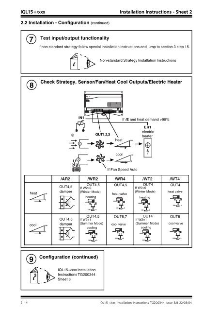
) 5 JH= JA C O 1, 5 A HE= 5 2.2 Installation - Configuration (continued) 7 Test input/output functionality If non standard strategy follow special installation instructions and jump to section 3 step 15. Non-standard Strategy Installation Instructions 8 Check Strategy, Sensor/Fan/Heat Cool Outputs/Electric Heater # IN1 If /E and heat demand >99% 6 S OUT1,2,3 heat ER1 electric heater cool S heat If Fan Speed Auto / AR2 / WR2 / WR4 / WT2 /WT4 OUT4,5 OUT4,5 OUT4,5 OUT4 If W2=0 If W2=0 OUT4 damper (Winter Mode) heat valve (Winter Mode) heat valve heating heating cool OUT4,5 damper OUT4,5 If W2=1 (Summer Mode) cooling OUT6,7 cool valve OUT4 If W2=1 (Summer Mode) cooling OUT6 cool valve 9 3 Configuration (continued) IQL15+/xxx Installation Instructions TG200344 Sheet 3
) 5 JH= JA C O 1, 5 A HE= 5 ) 5 JH= JA C O 1, 5 A HE= ) 5 JH= JA C O 1, 5 A HE= 5 5 SHEET 3: Installation Instructions - Sheet 3 3. Installation - Configuration (continued) 10 Fixing/ Configuration 2 11 # IQL15+/xxx Installation Instructions, TG200344 - Sheet 2 3 Check Operation - Window Contact Input if Window Mode (W5=1) Window IN5 OUT1, 2, 3 heat cool fan off heat / AR2 / WR2 / WR4 / WT2 /WT4 OUT4,5 damper OUT4,5 OUT4,5 heat valve OUT4 OUT4 heat valve cool damper goes to neutral valve closes OUT6,7 cool valve valve closes OUT6 cool valve 12 Check Operation - Pushbutton or PIR Input 13 Check Operation - Local SP Adjust # # If Fan Speed Auto PIR if in standby Pushbutton if non-occupied or standby IN4 OUT1, 2, 3 fan on see table section 2.2 step 8 Pb/PIR input type selected by configuration parameter W6 - see step 15 . Pushbutton can be provided by TB/TS/KE, /KEF, or RD-IQL/KOS, /KOSF (see section 1.3 step 8) IN2 OUT1, 2, 3 heat cool If Fan Speed Auto Local adjustment can be provided by TB/TS/K, /KE, /KEF or RD-IQL/K, /KOS, /KOSF (see section 1.3 step 8). Wait 6 secs at each end to calibrate potentiometer see table section 2.2 step 8
- Page 1 and 2: ! 8 = ! & ! " # $ % " # $ % &
- Page 3 and 4: ) 5 JH= JA C O 1, 5 A HE= 5 )
- Page 5 and 6: ) 5 JH= JA C O 1, 5 A HE= 5 )
- Page 7: ) 5 JH= JA C O 1, 5 A HE= 5
- Page 11 and 12: 3. Installation - Configuration (co
) <br />
5 JH= JA C O<br />
1,<br />
5 A HE= <br />
5<br />
<br />
<br />
2.2 Installation - Configuration (continued)<br />
7<br />
Test input/output functionality<br />
If non standard strategy follow special installation instructions and jump to section 3 step 15.<br />
Non-standard Strategy Installation Instructions<br />
8<br />
Check Strategy, Sensor/Fan/Heat Cool Outputs/Electric Heater<br />
# <br />
<br />
<br />
IN1<br />
If /E and heat demand >99%<br />
6<br />
S<br />
OUT1,2,3<br />
heat<br />
<br />
<br />
ER1<br />
electric<br />
heater<br />
cool<br />
<br />
S<br />
<br />
heat<br />
<br />
<br />
If Fan Speed Auto<br />
/ AR2 / WR2<br />
/ WR4<br />
/ WT2<br />
/WT4<br />
OUT4,5<br />
OUT4,5 OUT4,5 OUT4<br />
If W2=0<br />
If W2=0<br />
OUT4<br />
damper (Winter Mode)<br />
heat valve<br />
(Winter Mode) heat valve<br />
heating<br />
heating<br />
<br />
<br />
<br />
<br />
<br />
<br />
<br />
<br />
cool<br />
<br />
OUT4,5<br />
damper<br />
OUT4,5<br />
If W2=1<br />
(Summer Mode)<br />
cooling<br />
OUT6,7<br />
cool valve<br />
OUT4<br />
If W2=1<br />
(Summer Mode)<br />
cooling<br />
OUT6<br />
cool valve<br />
<br />
<br />
<br />
<br />
<br />
<br />
<br />
<br />
<br />
9<br />
3<br />
Configuration (continued)<br />
IQL15+/xxx Installation<br />
Instructions TG200344<br />
Sheet 3


