

1 - PNet - Trend
1 - PNet - Trend
1 - PNet - Trend
- No tags were found...

Create successful ePaper yourself
Turn your PDF publications into a flip-book with our unique Google optimized e-Paper software.
! 8 = <br />
!<br />
&<br />
! " # $ %<br />
" # $ % & ' ! " # $ % & ' <br />
) <br />
5 JH= JA C O<br />
1,<br />
5 A HE= <br />
! " #<br />
<br />
+ <br />
+ <br />
! " # $ % &<br />
+<br />
5<br />
5 4 8<br />
2 1<br />
<br />
<br />
' ! ! !<br />
! 8 = <br />
!<br />
5 JH= JA C O<br />
1,<br />
5 A HE= <br />
& ! " # $ %<br />
5 4 8<br />
! " # 2 1<br />
<br />
- 4 <br />
" 8<br />
+ + <br />
" 8<br />
+<br />
<br />
<br />
" # $ % & ' ! " # $ % & ' ! " # $ % &<br />
' ! ! !<br />
) <br />
5<br />
<br />
<br />
<br />
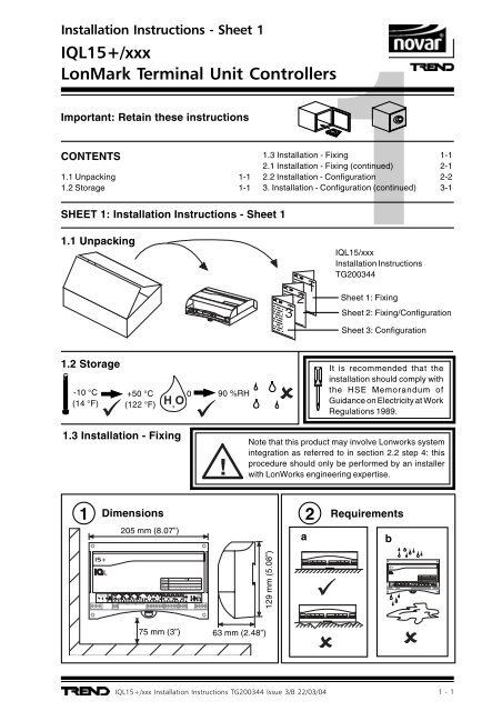
Important: Retain these instructions<br />
CONTENTS<br />
1.1 Unpacking 1-1<br />
1.2 Storage 1-1<br />
SHEET 1: Installation Instructions - Sheet 1<br />
1<br />
1.3 Installation - Fixing 1-1<br />
2.1 Installation - Fixing (continued) 2-1<br />
2.2 Installation - Configuration 2-2<br />
3. Installation - Configuration (continued) 3-1<br />
1.1 Unpacking<br />
1<br />
2<br />
3<br />
IQL15/xxx<br />
Installation Instructions<br />
TG200344<br />
Sheet 1: Fixing<br />
Sheet 2: Fixing/Configuration<br />
Sheet 3: Configuration<br />
1.2 Storage<br />
-10 °C<br />
(14 °F)<br />
+50 °C<br />
(122 °F)<br />
0 <br />
0<br />
90 %RH<br />
It is recommended that the<br />
installation should comply with<br />
the HSE Memorandum of<br />
Guidance on Electricity at Work<br />
Regulations 1989.<br />
1.3 Installation - Fixing<br />
!<br />
Note that this product may involve Lonworks system<br />
integration as referred to in section 2.2 step 4: this<br />
procedure should only be performed by an installer<br />
with LonWorks engineering expertise.<br />
1<br />
Dimensions<br />
205 mm (8.07”)<br />
a<br />
2<br />
Requirements<br />
b<br />
# <br />
<br />
<br />
<br />
- 4 <br />
" 8 " 8<br />
129 mm (5.08”)<br />
# <br />
<br />
75 mm (3”)<br />
63 mm (2.48”)
# <br />
# <br />
<br />
! 8 = <br />
+<br />
!<br />
<br />
! 8 = <br />
+<br />
!<br />
) <br />
5 JH= JA C O<br />
1,<br />
5 A HE= <br />
5<br />
<br />
& ! " # $ %<br />
5 4 8<br />
! " # 2 1<br />
<br />
- 4 <br />
" 8 " 8<br />
+ <br />
+<br />
<br />
" # $ % & ' ! " # $ % & ' <br />
<br />
! " # $ % &<br />
' ! ! !<br />
) <br />
5 JH= JA C O<br />
1,<br />
5 A HE= <br />
5<br />
<br />
& ! " # $ %<br />
5 4 8<br />
! " # 2 1<br />
<br />
- 4 <br />
" 8 " 8<br />
+ <br />
+<br />
<br />
" # $ % & ' ! " # $ % & ' <br />
<br />
! " # $ % &<br />
' ! ! !<br />
! 8 = <br />
!<br />
&<br />
! 8 = <br />
!<br />
! " # $ %<br />
" # $ % & ' ! " # $ % & ' <br />
" 8<br />
5 JH= JA C O<br />
1,<br />
5 A HE= <br />
& ! " # $ %<br />
5 4 8<br />
! " # 2 1<br />
<br />
- 4 <br />
" 8<br />
+ + <br />
" 8<br />
+<br />
<br />
<br />
" # $ % & ' ! " # $ % & ' ! " # $ % &<br />
' ! ! !<br />
" 8<br />
) <br />
5 JH= JA C O<br />
1,<br />
5 A HE= <br />
) <br />
5<br />
5 4 8<br />
! " # 2 1<br />
+ + <br />
+<br />
<br />
<br />
<br />
! " # $ % &<br />
5<br />
' ! ! !<br />
# <br />
<br />
) <br />
5 JH= JA C O<br />
1,<br />
5 A HE= <br />
5<br />
<br />
! " #<br />
! 8 = <br />
<br />
<br />
" 8 = + + <br />
4 - 6<br />
" 8 " 8<br />
+ <br />
! " # $ % & ' ! " # $ <br />
% & ' <br />
! 8 = <br />
!<br />
&<br />
! " # $ %<br />
" # $ % & ' ! " # $ % & ' <br />
! 8 = <br />
!<br />
&<br />
" 8<br />
" 8<br />
) <br />
5 JH= JA C O<br />
1,<br />
5 A HE= <br />
! " #<br />
<br />
+ <br />
+ <br />
! " # $ % &<br />
! " # $ %<br />
" # $ % & ' ! " # $ % & ' <br />
" 8<br />
" 8<br />
+<br />
) <br />
5 JH= JA C O<br />
1,<br />
5 A HE= <br />
5<br />
5 4 8<br />
2 1<br />
<br />
<br />
' ! ! !<br />
5<br />
5 4 8<br />
! " # 2 1<br />
+ + <br />
+<br />
<br />
<br />
<br />
! " # $ % &<br />
' ! ! !<br />
<br />
<br />
1.3 Installation - Fixing (continued)<br />
c<br />
2<br />
Requirements (continued)<br />
d<br />
# <br />
If not installed well outside normal<br />
reach (e.g behind false ceiling)<br />
<br />
e<br />
0 <br />
0 °C<br />
(32 °F)<br />
0<br />
+45 °C<br />
(113 °F)<br />
90 %RH<br />
Protection: IP20<br />
f<br />
Avoid locations where corrosive<br />
fumes or explosive vapours are<br />
present. Avoid electrical noise<br />
interference<br />
3<br />
Mounting<br />
189 mm (7.44”)<br />
4 holes<br />
# <br />
either surface mount<br />
114 mm<br />
(4.49”)<br />
<br />
<br />
- 4 <br />
or DIN rail mount<br />
∅ 6 mm<br />
(0.24”)<br />
a b c d<br />
# <br />
# <br />
<br />
<br />
<br />
<br />
- 4 <br />
- 4 <br />
4<br />
Lift Hinged Cover<br />
b<br />
c<br />
a<br />
WARNING: Failure to use a screwdriver<br />
to open the cover will cause damage to<br />
the unit.
) <br />
5 JH= JA C O<br />
1,<br />
5 A HE= <br />
5<br />
) <br />
5 JH= JA C O<br />
1,<br />
5 A HE= <br />
5<br />
<br />
<br />
1.3 Installation - Fixing (continued)<br />
5<br />
Connect Power<br />
/24VAC option<br />
IQL consumption<br />
) <br />
5 JH= JA C O<br />
1,<br />
5 A HE= <br />
5<br />
<br />
<br />
1.3 Installation - Fixing (continued)<br />
6<br />
Connect Lon (continued)<br />
LonMark<br />
Device<br />
IQL<br />
Lonworks bus<br />
LINC<br />
LINC<br />
IQ Outstations<br />
IQ Outstation<br />
Normal IQ System current loop Lan cable is not<br />
recommended<br />
Do not use screened cable<br />
Cable<br />
Max<br />
bus length<br />
Max node to node<br />
B elden 85102 500<br />
m (545 yds)<br />
500 m (545 yds)<br />
IQ system<br />
TP/1/0/16/HF/200 500<br />
m (545 yds) 400 m (430 yds)<br />
(Belden 8471)<br />
U L Level IV, 22 AWG 500<br />
m (545 yds)<br />
400 m (430 yds)<br />
J Y(St) Y2 x 2 x 0.8 500<br />
m (545 yds)<br />
320 m (350 yds)<br />
TIA5268A Cat. 5,<br />
24 AWG<br />
450<br />
m (490 yds) 250 m (270 yds)<br />
Terminal size 0.5 to 2.5 mm 2 (14 to 20 AWG)<br />
If used with LPT-10 (powered bus), cable lengths differ - see “Link Power Transceiver<br />
User’s Guide (078-0105-01C)”.<br />
Connect Inputs and Outputs<br />
7<br />
If non standard strategy, follow<br />
special installation instructions and<br />
jump to section 2.1 step 14<br />
Non-standard Strategy<br />
Installation Instructions<br />
8<br />
! " #<br />
+ + <br />
+<br />
Connect Inputs<br />
Terminal size 0.5 to<br />
2.55 mm 2 (14 to<br />
20 AWG)<br />
# <br />
<br />
<br />
Sensors TB/TS, TB/TS/K, TB/TS/KE, TB/TS/KEF<br />
recommended; wire as shown below.<br />
9<br />
2<br />
! " #<br />
<br />
+ <br />
+ <br />
! " # $ % &<br />
2 1 3 6 5 4<br />
TE/TS /K /F /E<br />
Room Display Module (RD-IQL/K, /KOS,<br />
/KOSF) provides monitor and control; wired as<br />
shown below:<br />
polarity<br />
independent<br />
Note that the IQL must be<br />
correctly set up to use the<br />
RD-IQL, see section 3 step 15<br />
Note that terminal types COM and<br />
C should not be connected together<br />
Configure/Commission<br />
IQL15+/xxx Installation<br />
Instructions, TG200344 -<br />
Sheet 2<br />
+<br />
"<br />
+<br />
$ %<br />
RD-IQL<br />
<br />
Local<br />
Space<br />
Temperature<br />
Sensor<br />
! " # $ % &<br />
Auto<br />
Local Setpoint<br />
Adjust<br />
Potentiometer<br />
Off<br />
Fan Speed Select<br />
T<br />
Pushbutton<br />
or PIR input<br />
∆T<br />
Window or<br />
Alarm<br />
contact<br />
Pushbutton or PIR<br />
input type selected<br />
by configuration<br />
parameter W6<br />
PIR<br />
PIR<br />
TE/TS<br />
/ <br />
TE/TS/K<br />
/ <br />
TE/TS/KE<br />
/ <br />
TE/TS/KEF<br />
/ <br />
RD/IQL/K<br />
S / / /<br />
RD/IQL/KOS<br />
S / /<br />
RD/IQL/KOSF<br />
S S / /<br />
input included in TB or RD<br />
S separate input may be used<br />
/ Input either cannot be connected, or will be ignored<br />
Connection of separate device to input required
) <br />
5 JH= JA C O<br />
1,<br />
5 A HE= <br />
5<br />
) <br />
5 JH= JA C O<br />
1,<br />
5 A HE= <br />
5<br />
<br />
<br />
<br />
SHEET 2: Installation Instructions - Sheet 2<br />
2.1 Installation - Fixing (continued)<br />
10<br />
Fixing<br />
1<br />
11<br />
2<br />
Connect Heat/Cool Outputs<br />
(24 Vac, 400 mA maximum shared between<br />
24 Vac auxiliary output and all triac outputs used)<br />
# <br />
IQL15+/xxx Installation Instructions,<br />
TG200344 - Sheet 1<br />
<br />
<br />
/AR2 /WR2 /WR4<br />
< " 8 < " 8<br />
< " 8 < " 8<br />
< " 8 < " 8<br />
" # $ % " # $ % " # $ %<br />
# $ % & ' # $ % & ' # $ % & ' <br />
/WT2<br />
" # $ %<br />
< " 8 < " 8<br />
# $ % & ' <br />
/WT4<br />
" # $ %<br />
< " 8 < " 8<br />
# $ % & ' <br />
Raise<br />
Common<br />
Lower<br />
Heat/Cool<br />
Damper<br />
not used<br />
Raise<br />
Common<br />
Lower<br />
Heat or Cool<br />
Valve<br />
not used<br />
Raise<br />
Common<br />
Lower<br />
Raise<br />
Common<br />
Lower<br />
Heat Valve Cool Valve<br />
Heat or Cool<br />
Valve<br />
not used<br />
Heat Valve Cool Valve<br />
terminal size 0.5 to 2.5 mm 2 (14 to 20 AWG)<br />
12<br />
Connect Fan Outputs<br />
# <br />
<br />
<br />
5 A maximum @240 Vac resistive or inductive (cosø>=0.4)<br />
5A @ 30 Vdc (resistive), 2 A @ 24 Vdc (inductive, T
! 8 = <br />
!<br />
) <br />
5 JH= JA C O<br />
1,<br />
5 A HE= <br />
<br />
& ! " # $ %<br />
5 4 8<br />
! " # 2 1<br />
<br />
- 4 <br />
" 8<br />
+ + <br />
" 8<br />
+<br />
<br />
<br />
" # $ % & ' ! " # $ % & ' <br />
<br />
! " # $ % &<br />
5<br />
' ! ! !<br />
) <br />
5 JH= JA C O<br />
1,<br />
5 A HE= <br />
5<br />
) <br />
5 JH= JA C O<br />
1,<br />
5 A HE= <br />
5<br />
1, ) # ! $ # <br />
5 A HE= 13 N 9 4 " # #<br />
) <br />
5<br />
<br />
<br />
2.1 Installation - Fixing (continued)<br />
13<br />
&<br />
- 4 <br />
Connect Relay Output<br />
/E Electric Heater, /AUX Auxiliary Output<br />
10 A maximum @240 Vac resistive or<br />
inductive (cosø>=0.4), 28 Vdc (resistive)<br />
Arc suppression<br />
TG200208<br />
" #<br />
# <br />
Electric<br />
Heater<br />
<br />
<br />
For electric heater (/E), a thermal<br />
cutout should be fitted in the supply<br />
to an electric heater.<br />
terminal size 0.5 to 2.5 mm 2 (14 to 20 AWG)<br />
WARNING:<br />
The wires may be connected<br />
to hazardous voltages.<br />
Disconnect power before<br />
attempting any wiring.<br />
14<br />
Close Hinged Cover<br />
a<br />
b<br />
2.2 Installation - Configuration<br />
1<br />
Tear off Label Strip<br />
‘locate’<br />
2<br />
Switch On<br />
# <br />
<br />
1,<br />
5 A HE= <br />
00:A0:25:36:51:00<br />
IQL1xWR4_50100025<br />
) 117 5 027<br />
5 JH= JA C O IQL1x WR4 E 06<br />
1, 00:A0:25:36:51:00<br />
5 A HE= IQL1xWR4_50100025<br />
<br />
1<br />
3<br />
Check IQL/LINC on Lon<br />
IQL<br />
LonMark<br />
Device<br />
Lonworks bus<br />
LINC<br />
LINC<br />
# <br />
<br />
<br />
LON OK (green)<br />
IQ Outstations<br />
IQ Outstation<br />
Flashes every 24 s, ON after 1½ mins<br />
Flashes every 1 s (Deaf IQL. Check Lon)<br />
(Check Lon, LINCs)
) <br />
5 JH= JA C O<br />
1,<br />
5 A HE= <br />
5<br />
<br />
<br />
2.2 Installation - Configuration (continued)<br />
Install using LonWorks Network Manager Tool<br />
4 If a binding IQLs to LonMark devices<br />
or b LINCs version
) <br />
5 JH= JA C O<br />
1,<br />
5 A HE= <br />
5<br />
<br />
<br />
2.2 Installation - Configuration (continued)<br />
7<br />
Test input/output functionality<br />
If non standard strategy follow special installation instructions and jump to section 3 step 15.<br />
Non-standard Strategy Installation Instructions<br />
8<br />
Check Strategy, Sensor/Fan/Heat Cool Outputs/Electric Heater<br />
# <br />
<br />
<br />
IN1<br />
If /E and heat demand >99%<br />
6<br />
S<br />
OUT1,2,3<br />
heat<br />
<br />
<br />
ER1<br />
electric<br />
heater<br />
cool<br />
<br />
S<br />
<br />
heat<br />
<br />
<br />
If Fan Speed Auto<br />
/ AR2 / WR2<br />
/ WR4<br />
/ WT2<br />
/WT4<br />
OUT4,5<br />
OUT4,5 OUT4,5 OUT4<br />
If W2=0<br />
If W2=0<br />
OUT4<br />
damper (Winter Mode)<br />
heat valve<br />
(Winter Mode) heat valve<br />
heating<br />
heating<br />
<br />
<br />
<br />
<br />
<br />
<br />
<br />
<br />
cool<br />
<br />
OUT4,5<br />
damper<br />
OUT4,5<br />
If W2=1<br />
(Summer Mode)<br />
cooling<br />
OUT6,7<br />
cool valve<br />
OUT4<br />
If W2=1<br />
(Summer Mode)<br />
cooling<br />
OUT6<br />
cool valve<br />
<br />
<br />
<br />
<br />
<br />
<br />
<br />
<br />
<br />
9<br />
3<br />
Configuration (continued)<br />
IQL15+/xxx Installation<br />
Instructions TG200344<br />
Sheet 3
) <br />
5 JH= JA C O<br />
1,<br />
5 A HE= <br />
5<br />
) <br />
5 JH= JA C O<br />
1,<br />
5 A HE= <br />
) <br />
5 JH= JA C O<br />
1,<br />
5 A HE= <br />
5<br />
5<br />
<br />
<br />
<br />
SHEET 3: Installation Instructions - Sheet 3<br />
3. Installation - Configuration (continued)<br />
10<br />
Fixing/<br />
Configuration<br />
2<br />
11<br />
# <br />
<br />
IQL15+/xxx Installation<br />
Instructions, TG200344 -<br />
Sheet 2<br />
3<br />
Check Operation - Window Contact Input<br />
if Window Mode (W5=1)<br />
<br />
Window<br />
IN5<br />
OUT1, 2, 3<br />
<br />
<br />
<br />
heat<br />
cool<br />
fan off<br />
<br />
<br />
<br />
heat<br />
/ AR2 / WR2<br />
/ WR4<br />
/ WT2<br />
/WT4<br />
OUT4,5<br />
damper<br />
OUT4,5<br />
OUT4,5<br />
heat valve<br />
OUT4<br />
OUT4<br />
heat valve<br />
<br />
<br />
<br />
<br />
<br />
<br />
cool<br />
damper goes<br />
to neutral<br />
<br />
valve closes<br />
<br />
OUT6,7<br />
cool valve<br />
<br />
valve closes<br />
<br />
OUT6<br />
cool valve<br />
<br />
<br />
<br />
<br />
12<br />
Check Operation<br />
- Pushbutton or PIR Input<br />
13<br />
Check Operation<br />
- Local SP Adjust<br />
# <br />
# <br />
<br />
<br />
If Fan Speed Auto<br />
<br />
<br />
PIR if in<br />
standby<br />
Pushbutton<br />
if non-occupied<br />
or standby<br />
IN4 OUT1, 2, 3<br />
fan on<br />
see table<br />
section 2.2<br />
step 8<br />
Pb/PIR input type selected by<br />
configuration parameter W6<br />
- see step 15 .<br />
Pushbutton can be provided by TB/TS/KE, /KEF, or<br />
RD-IQL/KOS, /KOSF (see section 1.3 step 8)<br />
IN2<br />
OUT1, 2, 3<br />
heat<br />
cool<br />
If Fan Speed Auto<br />
Local adjustment can be provided by TB/TS/K, /KE,<br />
/KEF or RD-IQL/K, /KOS, /KOSF (see section 1.3<br />
step 8).<br />
Wait 6 secs at each end to calibrate potentiometer<br />
<br />
<br />
<br />
<br />
see table<br />
section 2.2<br />
step 8
) <br />
5 JH= JA C O<br />
1,<br />
5 A HE= <br />
5<br />
<br />
<br />
3. Installation - Configuration (continued)<br />
14<br />
Check Operation - Fan Speed Select<br />
IN3<br />
) K J<br />
BB<br />
OUT1, 2, 3<br />
# <br />
<br />
<br />
If Occupied and Remote Fan Speed (K7) Auto<br />
Fan Speed Switch can be provided by TB/TS/KEF or<br />
RD-IQL/KOSF (see section 1.3 step 8)<br />
Set up Strategy Parameters<br />
15 if required<br />
Use IqlTool2 (see section 2.2 step 5 ) and text<br />
communications<br />
For standard strategies use table below, else refer to<br />
non-standard strategy installation instructions<br />
Parameter<br />
K1(V)<br />
K2(V)<br />
K3(V)<br />
K4(V)<br />
K5(V)<br />
K6(V)<br />
K7(V)<br />
K8(V)<br />
Label<br />
Remote<br />
Setpoint<br />
RemoteSpaceTemp<br />
OCC Deadbnd<br />
Standby<br />
Deadbnd<br />
NOCC Deadbnd<br />
Remote<br />
Occ<br />
Remote<br />
Fan Spd<br />
Remote<br />
SP Offset<br />
Function<br />
Base<br />
setpoint can be adjusted remotely<br />
Used<br />
if bound to Lon sensor, or if local sensor disconnected<br />
Deadband<br />
around setpoint during Occ<br />
Deadband<br />
around setpoint during Standby<br />
Deadband<br />
around setpoint during Nocc<br />
Sets<br />
state 0=Occ, 1=Nocc, 2=Bypass, 3=Standby<br />
Sets<br />
speed 0=off, 1=Low, 2=Med, 3=High, 4=Auto<br />
Used<br />
if bound to a Lon Sensor or if local adjust is disconnected<br />
20 ° C<br />
20 ° C<br />
1 ° C<br />
2 ° C<br />
12 ° C<br />
Default<br />
0=Occupied<br />
4=Auto<br />
0 ° C<br />
K15(V)<br />
W2(S)<br />
W3(S)<br />
O ffset range<br />
Defines<br />
range of Local SP adjust pot.<br />
S ummer Mode<br />
Winter<br />
(heat only) or Summer (cool only) (only used for /WR2, /WT2)<br />
Elec<br />
Disable<br />
Disable<br />
Electric Heater if set to I<br />
2 ° C<br />
O=Winter<br />
O=enable Elec<br />
W5(S)<br />
W6(S)<br />
W7(S)<br />
W8(S)<br />
L1(G)<br />
L1(I)<br />
L2(G)<br />
L2(I)<br />
Window mode<br />
O=Pb<br />
I=PIR<br />
Frost<br />
Condition<br />
Remote<br />
Shutdown<br />
Window contact if set to I, alarm contact if set to O<br />
PIR if set to I, Pushbutton if set to O<br />
Overrides<br />
heating to 98 % (not /AR2) if unoccupied<br />
Shuts<br />
off fan, and sets heat/cool to zero<br />
Heat<br />
Loop Gain<br />
40<br />
Heat<br />
Loop Integral<br />
Cool<br />
Loop Gain<br />
-40<br />
Cool<br />
Loop Integral<br />
O=alarm contact<br />
O=pushbutton<br />
O=no frost<br />
O=no shutdown<br />
0 mins<br />
0 mins<br />
Note that any changes to the strategy parameters should immediately be followed by a write to the address<br />
module, [text comms command, R(z=O), recommended], to commit changes to flash memory.<br />
If used with RD-IQL (see section 1.3 step 8), the following must be configured: Local Space Temp Type<br />
S9(Y=6), Local SP Adjust Type S10(Y=6), Local Fan Speed Type S11(Y=6), O=Pb I=PIR W6(S=O)<br />
default, Remote Fan Spd K7(V=4) default, followed by R(z=I) to write changes to flash and reset.<br />
Configuration for RD-IQL is facilitated by IqlTool2.<br />
If the sensor on IN1 is to be used, leave local Space Temp Type at default, S9(Y=1). If the fan speed<br />
switch on IN3 is to be used, leave Local Fan Speed type at default, S11 (Y=3).<br />
If required the strategy type may be changed (e.g. /AR2 to /WR2) but<br />
a /E strategy cannot be changed to a /AUX strategy or vice versa:<br />
IQL15+/xxx data<br />
sheet TA200367
3. Installation - Configuration (continued)<br />
16<br />
Set up System Core Firmware Module Parameters<br />
if required - see conditions<br />
Using IqlTool2 (see section 2.2 step 5) and text communications<br />
Parameter<br />
Setting<br />
Function<br />
Condition<br />
Note<br />
R(..address<br />
T(..Time<br />
U1(..User<br />
L - own address<br />
device<br />
address of IQL<br />
if required to rearrange<br />
Lans, address<br />
1, 2,<br />
4<br />
N - own LaN<br />
Lan<br />
number of IQL<br />
if required to rearrange<br />
1, 2<br />
Lans, address<br />
D - identifier<br />
identifier<br />
attribute of IQL<br />
For alarm ident, text<br />
1<br />
comms, IC comms<br />
F - attribute 2<br />
text<br />
comms attributes<br />
For<br />
text comms, IC comms<br />
1<br />
G - attribute 3<br />
1<br />
A - own Lan alarm address<br />
address and Lan of own<br />
to report Lan alarms to a 1<br />
R - Own Lan alarm Lan<br />
Lan alarm target supervisor<br />
1<br />
E - Internetwork alarm<br />
address and Lan of to report internetwork<br />
1<br />
address<br />
Internetwork alarm alarms to a supervisor (only<br />
T - Internetwork alarm Lan<br />
target<br />
for lowest addressed IQ<br />
System device on Lan)<br />
1<br />
r - LonWorks retry time<br />
i - LonWorks interpacket<br />
delay<br />
See IQ System LonWorks<br />
Products Engineering<br />
Manual for details<br />
a - LonWorks service class<br />
2<br />
b - router Buffer size<br />
m - LonWorks<br />
code<br />
Message<br />
g - generator number<br />
e - neuron id<br />
H - Hours<br />
N - Minutes<br />
D - Day of month<br />
buffer size<br />
(bytes)<br />
Default = 146<br />
code number.<br />
Default = 64<br />
unique<br />
identifier for<br />
neuron<br />
specifies smallest router<br />
buffer on system<br />
Code used by<br />
IQLs/LINCs/LONCs, all<br />
LINCs/LONCs must use<br />
same code<br />
T o find PIN if lost<br />
(read only)<br />
To find PIN if lost; to<br />
identify Lon node<br />
Current<br />
time<br />
Current<br />
date<br />
If routers separate<br />
IQLs/LINCs/LONCs and<br />
have buffer size smaller that<br />
146 bytes - set to smallest<br />
buffer size. (minimum = 66)<br />
If message code being used<br />
by other users - must be<br />
exclusive to IQ System<br />
(read only)<br />
To synchronise time for<br />
alarms and logging<br />
To synchronise date for<br />
alarms and logging<br />
M - Month<br />
3<br />
Y - Year<br />
3<br />
l - Lan of system<br />
timemaster<br />
P - PIN<br />
l -level<br />
IQL timekeeper gets<br />
time sync from IQ at<br />
address 11 on this Lan<br />
PIN number in IQ<br />
authority<br />
level of PIN<br />
IQL will be timekeeper If this<br />
'l'<br />
parameter is non-zero<br />
and own address = 11<br />
To protect from<br />
unauthorised changes<br />
Note 1: IqlTool2 facilitates setting of these parameters across the Lon segment<br />
Note 2: Changing any of these parameters results in a controller reset (clears down time and and sensor logs)<br />
Note 3: Any changes to these parameters should immediately be followed by a write to the address<br />
module, [text comms command, R(z=O), recommended], to commit changes to flash memory.<br />
Note 4: IqlTool2 facilitates setting to timekeeper (sets up timemaster Lan and changes own address to 11)<br />
Note 5: Message code can only be changed by text comms if 'lonworks managed' (read only) is set to No .<br />
Note 6: If PIN is forgotten see note in section 2.2 step 5<br />
2<br />
2<br />
2<br />
2, 5<br />
3<br />
3, 4<br />
3, 6<br />
No<br />
protection if zero<br />
3<br />
17<br />
Set up Lan System<br />
if required<br />
Check Lan<br />
PowerTool or Wupdn<br />
IQL<br />
Lon<br />
LINC<br />
IQ<br />
Use PowerTool or Wupdn and terse text<br />
communications<br />
LINC Installation Instructions<br />
TG103062<br />
IQ System LonWorks<br />
Products Engineering<br />
Manual - TE200292
3. Installation - Configuration (continued)<br />
18<br />
Set up IC Comms from IQL<br />
if required<br />
Use IqlTool2 (see section 2.2 step 5) and text communications<br />
IC Comms Module Nx(.. - (x=1 to y; y=4 for standard strategies)<br />
Parameter<br />
Function<br />
A - Remote device address<br />
If zero, 'global to' comms. If non-zero specifies<br />
target device address for 'data to' comms<br />
For 'global to' comms only, attribute of target IQ,<br />
B - Attribute<br />
references attribute in address module (0 'no<br />
attribute', - all IQs on Lan,1 'identifier', 2 'attribute<br />
2', 3 'attribute 3')<br />
N - Remote Lan<br />
Target IQ Lan number; if Lan zero, address zero,<br />
specifies global global<br />
I - Interval<br />
Interval between sending (minutes)<br />
S - Significant change Amount analogue must change before sending<br />
M - Source item string Item and parameter being sent (e.g. S1(V) )<br />
E - Destination module number No. of destination module receiving IC comms<br />
T - Destination type<br />
Type of destn module receiving comms (e.g. W,K)<br />
Lon<br />
LCI<br />
IQL<br />
S1<br />
S8<br />
K1<br />
K2<br />
K8<br />
I1<br />
I8<br />
W1<br />
W7<br />
W8<br />
Nx<br />
Nx<br />
IC Comms<br />
LINC<br />
IQ<br />
19<br />
Set up IC Comms from IQ<br />
if required<br />
IC Comms ‘direction’ in IQ must be:<br />
Global To, Min, Max, Sum, or<br />
Average (directions 2 to 6)<br />
see IQ Configuration<br />
Manual 90-1533<br />
20<br />
Lon<br />
Set up Communications from<br />
Supervisor if required<br />
e.g. 963 (drag and drop values)<br />
Note that standard strategy pages<br />
are available for 963 from<br />
Partnernet<br />
Terse Text Comms<br />
Use SET, PowerTool, or Wupdn and terse text<br />
communications<br />
IQL<br />
S1<br />
LINC<br />
Lon<br />
S8<br />
S1<br />
S16<br />
K1<br />
K8<br />
I1<br />
I16<br />
IQL<br />
A1<br />
A16<br />
A17<br />
A24<br />
B1,0<br />
B2,7<br />
W1 B18,0<br />
W8 B19,7<br />
LINC<br />
Nx<br />
Nx<br />
IQ<br />
IC Comms<br />
K1<br />
K2<br />
K8<br />
I1<br />
I8<br />
W1<br />
W7<br />
W8<br />
Note that any changes to the strategy parameters<br />
should immediately be followed by a write to the<br />
address module, [text comms command, R(z=O),<br />
recommended], to commit changes to flash<br />
memory.<br />
IQ


