Aim of the experiment: Fault scenario simulation in a feeder ...
Aim of the experiment: Fault scenario simulation in a feeder ...
Aim of the experiment: Fault scenario simulation in a feeder ...
- No tags were found...

Create successful ePaper yourself
Turn your PDF publications into a flip-book with our unique Google optimized e-Paper software.
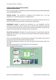
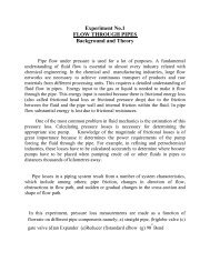
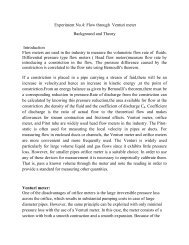
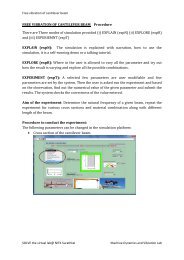
<strong>Aim</strong> <strong>of</strong> <strong>the</strong> <strong>experiment</strong>: <strong>Fault</strong> <strong>scenario</strong> <strong>simulation</strong> <strong>in</strong> a <strong>feeder</strong><br />
Whenever fault happens <strong>in</strong> a <strong>feeder</strong>, <strong>the</strong> circuit breaker placed <strong>in</strong> <strong>the</strong> <strong>feeder</strong> trips<br />
due to high fault current. This will alter <strong>the</strong> load<strong>in</strong>g conditions <strong>in</strong> <strong>the</strong> substation.<br />
Whenever fault occurs, Alarm will be generated <strong>in</strong>dicat<strong>in</strong>g tripp<strong>in</strong>g <strong>of</strong> circuit<br />
breaker.<br />
This process is simulated as below:<br />
<strong>Fault</strong> on <strong>feeder</strong>1<br />
(a) Prefault condition is taken as<br />
45A flow<strong>in</strong>g <strong>in</strong> Feeder 1(with 3 switches on)<br />
30A flow<strong>in</strong>g <strong>in</strong> Feeder 2(with 2 switches on)<br />
Read<strong>in</strong>g <strong>of</strong> meters<br />
M1 M2 M3<br />
V (kV) I (A) P (kW)<br />
V (kV) I (A) P (kW)<br />
V (kV) I (A) P (kW)<br />
11 45 857.36<br />
11 30 571.57<br />
33 25 1423.94<br />
(b) <strong>Fault</strong> on <strong>feeder</strong>1 is simulated by short.<br />
(c) The circuit breaker CB6 opens, CB6 color changes to blue.<br />
(d) Alarm gets generated.<br />
Read<strong>in</strong>g <strong>of</strong> meters changes:<br />
M1 M2 M3<br />
V (kV) I (A) P (kW)<br />
V (kV) I (A) P (kW)<br />
V (kV) I (A) P (kW)<br />
11 0 0<br />
11 30 571.57<br />
33 10 571.57<br />
Department Of Electrical and Electronics Eng<strong>in</strong>eer<strong>in</strong>g, NITK. 1
<strong>Fault</strong> on <strong>feeder</strong>2<br />
(a) Prefault condition is taken as<br />
45A flow<strong>in</strong>g <strong>in</strong> Feeder 1(with 3 switches on)<br />
30A flow<strong>in</strong>g <strong>in</strong> Feeder 2(with 2 switches on)<br />
Read<strong>in</strong>g <strong>of</strong> meters:<br />
M1 M2 M3<br />
V (kV) I (A) P (kW)<br />
V (kV) I (A) P (kW)<br />
V (kV) I (A) P (kW)<br />
11 45 857.36<br />
11 30 571.57<br />
33 25 1423.94<br />
(b) <strong>Fault</strong> on <strong>feeder</strong>2 is simulated by short.<br />
(c) The circuit breaker CB7 opens, CB7 color changes to blue.<br />
(d) Alarm gets generated.<br />
Read<strong>in</strong>g <strong>of</strong> meters changes:<br />
M1 M2 M3<br />
V (kV) I (A) P (kW)<br />
V (kV) I (A) P (kW)<br />
V (kV) I (A) P (kW)<br />
11 45 857.36<br />
11 0 0<br />
33 15 857.36<br />
Department Of Electrical and Electronics Eng<strong>in</strong>eer<strong>in</strong>g, NITK. 2